IFM LI513 Series User manual

Operating instructions
Binary level sensor
LI513x
11410834 / 00 08 / 2021
UKUK

2
Contents
1 Preliminary note���������������������������������������������������������������������������������������������������3
1�1 Symbols used ������������������������������������������������������������������������������������������������3
2 Safety instructions �����������������������������������������������������������������������������������������������4
3 Items supplied������������������������������������������������������������������������������������������������������5
4 Functions and features ����������������������������������������������������������������������������������������5
4�1 Application area ���������������������������������������������������������������������������������������������5
4�2 Restriction of the application area �����������������������������������������������������������������5
5 Function���������������������������������������������������������������������������������������������������������������6
5�1 Measuring principle level �������������������������������������������������������������������������������6
5�2 Measuring principle temperature �������������������������������������������������������������������6
5�3 Features of the unit����������������������������������������������������������������������������������������7
5�3�1 IO-Link ��������������������������������������������������������������������������������������������������7
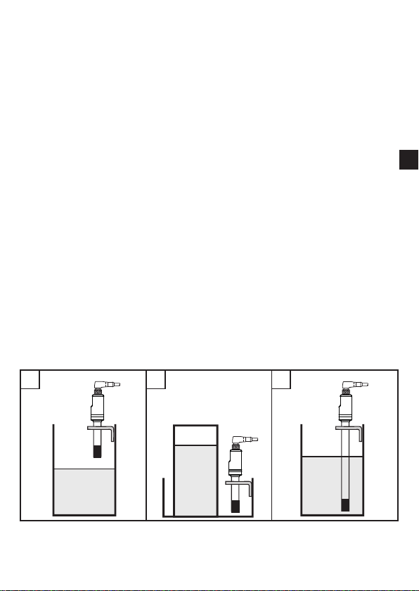
5�4 Application examples�������������������������������������������������������������������������������������7
6 Installation������������������������������������������������������������������������������������������������������������8
6�1 Installation location / environment �����������������������������������������������������������������8
6�2 Installation procedure �����������������������������������������������������������������������������������8
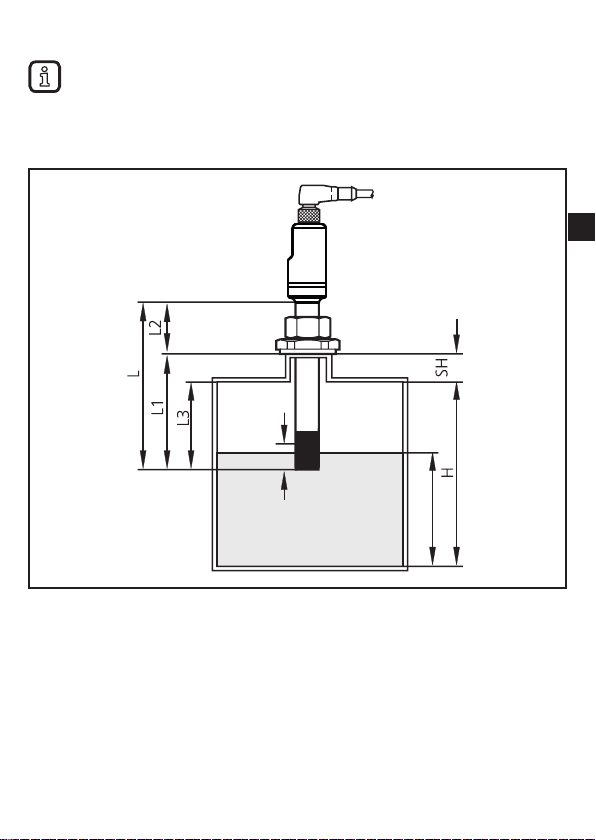
6�3 Set the installation depth �������������������������������������������������������������������������������9
7 Electrical connection������������������������������������������������������������������������������������������10
8 Operating and display elements ������������������������������������������������������������������������ 11
9 Parameter setting ���������������������������������������������������������������������������������������������� 11
9�1 Parameter setting via the teach button��������������������������������������������������������12
9�1�1 Unlock unit������������������������������������������������������������������������������������������12
9�1�2 Set for empty tank condition ���������������������������������������������������������������13
9�1�3 Set for full tank condition ��������������������������������������������������������������������14
9�2 Parameter setting via IO-Link ����������������������������������������������������������������������15
9�2�1 Parameter setting via PC and IO-Link master ������������������������������������15
9�2�2 Parameter setting via memory plug����������������������������������������������������15
9�2�3 Parameter setting during operation ����������������������������������������������������15
9�2�4 Adjustable parameters and system commands����������������������������������16
9�2�5 Example parameter setting via IO-Link ����������������������������������������������18
10 Operation���������������������������������������������������������������������������������������������������������19
10�1 Function check ������������������������������������������������������������������������������������������19

3
UK
10�2 Operating and diagnostic messages via IO-Link ��������������������������������������19
10�3 Operating indication by LEDs ��������������������������������������������������������������������19
10�4 Output response in different operating states��������������������������������������������20
11 Technical data and scale drawing ��������������������������������������������������������������������20
12 Maintenance / Transport����������������������������������������������������������������������������������20
13 Factory setting �������������������������������������������������������������������������������������������������21
1 Preliminary note
1.1 Symbols used
►Instruction
> Reaction, result
[…] Designation of keys, buttons or indications
→Cross-reference
Important note
Non-compliance may result in malfunction or interference�
Information
Supplementary note

4
2 Safety instructions
• The device described is a subcomponent for integration into a system�
- The system architect is responsible for the safety of the system�
- The system architect undertakes to perform a risk assessment and to create
documentation in accordance with legal and normative requirements to be
provided to the operator and user of the system� This documentation must
contain all necessary information and safety instructions for the operator, the
user and, if applicable, for any service personnel authorised by the architect
of the system�
• Read this document before setting up the product and keep it during the entire
service life�
• The product must be suitable for the corresponding applications and
environmental conditions without any restrictions�
• Only use the product for its intended purpose (→ Functions and features).
• Only use the product for permissible media (→ Technical data).
• If the operating instructions or the technical data are not adhered to, personal
injury and/or damage to property may occur�
• The manufacturer assumes no liability or warranty for any consequences
caused by tampering with the product or incorrect use by the operator�
• Installation, electrical connection, set-up, operation and maintenance of the
product must be carried out by qualified personnel authorised by the machine
operator�
• The unit complies with the standard EN 61000-6-4� The unit may cause radio
interference in domestic areas� If interference occurs, the user must take
appropriate actions�
• Protect units and cables against damage�

5
UK
3 Items supplied
• Level sensor LI513x (x = coding of the probe length)
• Operating instructions or Quick setup guide
• Stainless steel tube clip (for fixing the installation height)
In addition, the following is necessary for installation and operation:
• Mounting material (→ Accessories)
Only use accessories from ifm electronic gmbh!
The optimum function is not ensured when using components from other
manufacturers�
Accessories: www�ifm�com
4 Functions and features
The unit monitors the level (point level) and the temperature of liquid media in
tanks�
4.1 Application area
Water, hydrous media, oils, oil-based media, emulsions�
4.2 Restriction of the application area
• Use the product only for media to which the wetted materials are sufficiently
resistant (→ Technical data sheet).
• The unit is not suitable for hygienic areas�
• The unit is not suitable for applications where the probe is subjected to
permanent and high mechanical stress
(e�g� bulk materials, abrasive media or fast flowing media containing solid
particles).
• Highly conductive foam can trigger a switching operation� Check the
consequences by performing a test in your application!

6
5 Function
5.1 Measuring principle level
The unit operates on the capacitive measuring principle� In direct contact with
the medium the unit detects whether the requested level (point level) has been
reached�
The relative permittivity (before: dielectric constant) of a medium is important
for its detection� Media with a relative permittivity greater than 1�8 are reliably
detected�
Electrically conductive and non conductive media are detected�
Relative permittivity of common media
Mineral oil ≈ 2
Coolant emulsion ≈ 25...75
Glycol ≈ 37
Water ≈ 80
The unit operates with radial detection
characteristics� Therefore media below the active
zone (A) are not detected.
When the unit is perfectly adjusted, the
presence of certain media can be detected
while build-up or foam is suppressed�
A: Active zone (28 mm)
5.2 Measuring principle temperature
The temperature is detected by a temperature element at the lower end of the
probe and electronically evaluated�

7
UK
5.3 Features of the unit
• The unit versions are offered with different probe lengths�
• Point level selectable by the installation length (→ 6)�
• Parameter setting using the teach button (→ 9.1) or via IO-Link (→ 9.2)�
• The unit has two switching outputs:
- Output OUT1 is assigned to the process value "Level"�
- Output OUT2 can be assigned to the process value "Level" or "Temperature"�
• Adjustment function (empty and full adjustment) to the medium to be detected.
• Defined state in case of a fault (→ 9.2.4)
5.3.1 IO-Link
The device has an IO-Link communication interface which requires an IO-Link
capable module (IO-Link master).
The IO-Link interface enables direct access to the process and diagnostic data
and provides the possibility to set the parameters of the unit during operation�
In addition, communication is possible via a point-to-point connection with a USB
IO-Link master�
The IODDs necessary for the configuration of the unit, detailed information about
process data structure, diagnostic information, parameter addresses and the
necessary information about the required IO-Link hardware and software can be
found at www�ifm�com�
5.4 Application examples
1 2 3
1: Overflow protection in a supply tank for coolant emulsion�
2: Leakage monitoring in the overflow vessel of a hydraulic power unit�
3: Minimum level monitoring�

8
6 Installation
6.1 Installation location / environment
• Vertical installation from the top is preferred�
• The following minimum distances must be adhered to:
Distance tank bottom - end of the probe 10 mm
Distance metal tank wall - probe 20 mm
In case of plastic tanks:
If possible, install the unit in the middle of the tank to prevent capacitive interference by
objects outside the tank� When interference occurs:
► Provide for a metal screen (e.g. using a shielding plate, etc.).
Distance between several LI513x units (distance from the centre of a
probe to the centre of another probe):
Reference values for standard applications:
- Water / coolant emulsion in a grounded metal tank: 40 mm
- Oils in a grounded metal tank: 100 mm
- Water, media similar to water and oils in an ungrounded plastic
tank:
200 mm
Distance between LI513x and LKxxxx units:
(Distance from the centre of a probe to the centre of another probe)
60 mm
Metal-free space around the inductive teach button (→ 8) 20 mm
The indications refer to the factory setting (→ 13)� Depending on the
application and the customised settings, smaller distances may also be
possible� In this case:
►Check the function by performing an application test�
6.2 Installation procedure
The unit is mounted using a mounting clamp or an adapter (→ Accessories).
►Observe the installation instructions for the adapter or mounting clamp used�
►Weld or screw the adapter into the tank / pipe�

9
UK
6.3 Set the installation depth
The unit switches when the level reaches the active zone (A).
The exact position (response level) depends on the following factors:
• characteristics of the medium
• installation conditions
• adjustment of the unit (→ 9)
G
A
G = point level L1 = installation depth
H = tank height L2 = outside length
SH = height of the connection piece L3 = mounting length (at least 60 mm)
L = probe length A = active zone (28 mm)
►Select the installation depth L1 and the outside length L2 so that at least half
the active zone (A) is covered when the point level G has been reached:
L1 = (H - G) + ½ A + SH and L2 = L - L1
►Fix the set installation depth with the supplied stainless steel tube clip�

10
7 Electrical connection
The unit must be connected by a qualified electrician�
The national and international regulations for the installation of electrical
equipment must be adhered to�
Voltage supply according to EN 50178, SELV, PELV�
For marine applications (if approval available for the device), additional
surge protection is required�
►Disconnect power�
►Connect the unit as follows:
Core colours
43
2 1
BN
WH
BK
BU
4
1
3
2OUT2
L+
L
OUT1
BK black
BN brown
BU blue
WH white
OUT1: switching output / IO-Link
OUT2: switching output
Colours to DIN EN 60947-5-2
Example circuits
2 x PnP 2 x nPn
L
L+
3
4
2
1
BU
BK
WH
BN
2: OUT2
4: OUT1 L
L+
3
4
2
1
BU
BK
WH
BN
2: OUT2
4: OUT1

11
UK
8 Operating and display elements
1
12
3
On delivery, the two yellow LEDs (LED1 and LED2) indicate the switching
status of output OUT1� This can be configured via IO-Link (→ 9.2.4)�
Fig� 1: view of the unit
1: inductive teach button
Fig� 2: top view
1: LED1 (yellow) = switching status OUT1
2: LED2 (yellow) = switching status OUT1
(OUT2)
3: LED3 (green) = operating status
The inductive teach button is actuated with a metal object (e�g� a
screwdriver 1 x 5,5 mm) by applying it flat to the teach surface.
No operation is triggered by actuating the button briefly (less than 1 s) or
continuously (longer than 30 s) (static activation)!
9 Parameter setting
On delivery, the unit is set to detecting water-based media (e.g. coolant emulsion).
In many cases the factory setting is sufficient, so that no further settings are
required�
► Check the function by performing an application test) (→ 10)�
In case the factory settings are not sufficient:
►Adapt the unit to the application�
The unit can be parameterized using the inductive teach button (→ 9.1) or
via IO-Link (→ 9.2)� Some functions are only available via IO-Link�

12
►Make sure that there will be no malfunctions / dangerous operation in
your plant�
9.1 Parameter setting via the teach button
The teach button can be used to unlock the unit in a first step (→ 9.1.1) and
then to adjust the unit sensitivity�
The unit sensitivity is adjusted by carrying out an empty adjustment and / or
a full adjustment (→ 9.1.2) and (→ 9.1.2)�
The switching thresholds (set point and reset point) are automatically
defined with the adjustment procedure�
The teach operation only has an effect on the process value "level" while
always affecting both outputs (OUT1 and OUT2).
All other parameter settings can only be made via IO-Link (→ 9.2)�
Actuating the teach button: (→ 8)
The unit is locked at the beginning of operation and after 120 s of inactivity
(operating hurdle to avoid unintentional input of incorrect values).
9.1.1 Unlock unit
►Actuate the teach button for at least 10 s�
> The green LED3 flashes during these 10 s at approx�1 Hz� The expiry of the
10 s is acknowledged with a double flash (at approx. 2 Hz).
► Release the teach button (remove metal object).
> The green LED is lit permanently�
The unit is now unlocked�
After 120 s of inactivity, the unit locks itself again automatically�
Parameterisation can only be performed within this period�
The green LED will flash as signal if you try to perform operations while the
unit is locked� The unit remains locked if the teach button is released before
10 s have expired�

13
UK
9.1.2 Set for empty tank condition
By performing the empty adjustment, the unit is adjusted to the empty tank and the
installation conditions (e.g. the distance to the tank wall / structures in the tank).
Previous adjustment operations are deleted� By performing the empty adjustment,
the unit is adjusted to maximum sensitivity which is particularly suitable for media
with a low dielectric constant (e.g. oils).
1
►Empty the tank�
In case the unit is used as a level switch or
overflow prevention: Empty the tank until the
medium is at least 20 mm below the end of the
probe�
2►Unlock the unit (→ 9.1.1)
3
►Actuate the teach button for at least 1 s / not
longer than 4 s�
> First, the green LED3 goes out briefly, then
the two yellow LEDs flash slowly after 1 s (at
approx.1 Hz).
► Release the teach button (remove metal object).
> Successful completion of the empty adjustment
is acknowledged with a double flash of the
green LED (at approx. 2 Hz).
While the unit is in factory setting, both
yellow LEDs are off�
> The unit is ready for operation�
While the unit is in factory setting, output
1 (OUT1) is set to normally open and output
2 (OUT2) to normally closed.
Modify output configuration: (→ 9.2)�

14
9.1.3 Set for full tank condition
In case of aqueous media, in particular those where deposits or soiling are to be
expected, the empty adjustment is not necessary and a full adjustment can be
carried out immediately�
Where an empty adjustment has been carried out for aqueous media, it
must be followed by a full adjustment to achieve a perfect adjustment of
the unit sensitivity to the medium�
1►Fill the tank until the active zone (A → 6.3) is
completely covered�
2►Unlock the unit (→ 9.1.1)
3
►Actuate the teach button for at least 4 s / not
longer than 7 s�
> First, the green LED3 goes out briefly, then the
two yellow LEDs start flashing slowly after 1 s
(at approx. 1 Hz) before flashing quickly after 4 s
(at approx. 2 Hz).
► Release the teach button (remove metal object).
> Successful completion of the full adjustment is
acknowledged with a double flash of the green
LED (at approx. 2 Hz).
While the unit is in factory setting, both yellow
LEDs are lit�
> The unit is ready for operation�
While the unit is in factory setting, output
1 (OUT1) is set to normally open and output
2 (OUT2) to normally closed.
Modify output configuration: (→ 9.2)�

15
UK
9.2 Parameter setting via IO-Link
A PC with USB IO-Link master (→ 9.2.1) or a programmed memory plug (→ 9.2.2)
or a configured IO-Link environment (→ 9.2.3) is required to set the parameters�
9.2.1 Parameter setting via PC and IO-Link master
► Prepare PC, software and master. → Observe the operating instructions of the
respective units / software (→ 5.3.1)�
► Connect the unit to the USB IO-Link master (→ Accessories).
►Follow the menu of the IO-Link software�
►Set the parameters; adjustable parameters (→ 9.2.4)�
►Check if the parameter setting was accepted by the unit� If necessary, read
sensor again�
►Remove USB IO-Link master and put the unit into operation (→ 10)�
9.2.2 Parameter setting via memory plug
Via a memory plug (→ Accessories), a parameter set can be written/transferred to
the unit (→ 5.3.1)� This procedure may be used e�g� for duplicating the parameter
setting of one unit to another�
► Load suitable parameter set (e.g. using a PC) to the memory plug
→ observe the operating instructions of the memory plug.
►Make sure that the sensor has the original factory settings�
►Connect the memory plug between sensor and socket�
> When voltage is supplied, the parameter set is transferred from the memory
plug to the sensor�
►Remove the memory plug and put the unit into operation (→ 10)�
9.2.3 Parameter setting during operation
► Make sure that the sensor is connected to an IO-Link-capable module (master)
(→ 5.3.1)�
► Read the sensor using a suitable IO-Link software → observe the operating
instructions of the respective software�
►Set the parameters; adjustable parameters (→ 9.2.4)�
►Check if the parameter setting was accepted by the unit� If necessary, read
sensor again�
►Check whether the unit operates reliably�

16
9.2.4 Adjustable parameters and system commands
Parameter
uni�T Selection of the temperature unit:
[°C] = temperature is displayed in °C (degrees Celsius)
[°F] = temperature is displayed in °F (degrees Fahrenheit)
P-n Set output logic for the switching outputs:
[PnP] = positive switching
[nPn] = negative switching
SEL2 Allocation of switching output OUT2 to the process value:
[LEVL] = level1)
[TEMP] = temperature
LED mode Switching state display via LEDs (→ 8):
[OUT1] = The two yellow LEDs (LED1 and LED2) indicate the
switching status of output OUT1�
[OUT1+OUT2] = LED1 indicates the switching status of OUT1
and LED2 the switching status of OUT2�
ou1 Output configuration for switching output OUT1 (level)
[Hno] = hysteresis function / normally open
[Hnc] = hysteresis function / normally closed
[OFF] = output OFF (high impedance)
ou2 Output configuration for switching output OUT 2 (level /
temperature)
[Hno] = hysteresis function / normally open
[Hnc] = hysteresis function / normally closed
[Fno] = window function2) / normally open
[Fnc] = window function2) / normally closed
[OFF] = output OFF (high impedance)
SPx - LEVL Switch point 1 or 2 for level�
[SPx] must be greater than [rPx]� If [SPx] is set to
a value below [rPx], this is rejected by the device
software�
The values for [SPx] / [rPx] are set in per cent of the maximum
process value�
The process value is defined as follows:
Process value in air (not predamped): approx. 0 %
Process value in tap water = approx. 100 %3)
rPx - LEVL Switch-off point 1 or 2 for level

17
UK
SP2 (FH2) - TEMP Switch point 2 or upper temperature limit for window function
([SEL2]=[TEMP]).
[SP2 (FH2)] must be greater than [rP2 (FL2)].
If [SP2 (FH2)] is set to a value below [rP2 (FL2)], this is
rejected by the device software�
rP2 (FL2) - TEMP Switch point 2 or lower temperature limit for window function
([SEL2]=[TEMP]).
dS1 / dS2 Switching delay4) for OUT1 and OUT2.
Setting range 0�0���10�0 s
dr1 / dr2 Switching delay4) for OUT1 and OUT2.
Setting range 0�0���10�0 s
FOU1 / FOU2 Response of OUT1 or OUT2 in case of a fault:
[OFF] = switching output switches OFF in case of a fault�
[On] = switching output switches ON in case of a fault�
[OU] = switching output reacts according to process value,
if possible�
Lo�T Minimum value memory for the temperature
Hi�T Maximum value memory for the temperature
Unit locking�
Local parameter setting
[Open] = parameter setting via teach button is permitted�
[Locked] = parameter setting via teach button is locked�
1) This setting is not possible in combination with [ou2] = [Fno] or [Fnc]�
2) This setting is only possible in combination with [SEL2] = [TEMP].
3) Tap water in grounded metal tank
4) Response according to VDMA� According to VDMA the switch-on delay always has an
effect on SP, the switch-off delay always on rP irrespective of whether the normally open or
normally closed function is used�

18
System commands
Restore Factory
Settings
Restore Factory Settings�
Empty teach Empty adjustment, automatically sets the switching thresholds
SP and rP� More information: (→ 9.1)�
Full teach Full adjustment to the medium, automatically sets the switching
thresholds SP and rP� More information: (→ 9.1)�
Reset
[Hi�T] and [Lo�T]
Reset maximum and minimum value memory�
Flash On Visual indication (double flash) for localisation ON.
The indication automatically disappears after 1 minute�
Flash Off Visual indication (double flash) for localisation OFF.
For further information, please refer to the IODD description (→ www.ifm.com)
or to the context-specific parameter descriptions of the used parameter setting
software�
9.2.5 Example parameter setting via IO-Link
►Set the switching output OUT2 to temperature measurement�
Example: [SEL2] = [TEMP]
►The temperature output OUT2 shall be set as alarm output (as normally closed
with a high temperature threshold). Example: [ou2] = [Hnc]
►Set the alarm temperature to 80°C�
Example: [SP2 (FH2)-TEMP] = 80;
[rP2 (FL2)-TEMP] = 75.
►Transfer the sensor data to the unit�
►Carry out a full adjustment to the medium to be detected:
Fill the tank until the active zone (A → 6.3) of the unit is completely covered.
►Execute the system command [full teach]�
All other settings remain as set at the factory�

19
UK
10 Operation
10.1 Function check
After power-on the device is in the operating mode� It carries out its measurement
and evaluation functions and generates output signals according to the set
parameters�
►Check whether the unit operates reliably�
10.2 Operating and diagnostic messages via IO-Link
IODD and IODD descriptive text as a pdf file at: → www.ifm.com
10.3 Operating indication by LEDs
The following indications refer to the factory settings� In this state OUT1 = Hno
and OUT2 = Hnc�
Both yellow LEDs (LED1 and LED2, → 8) indicate the switching status of output
OUT1�
Operating status LED1
(yellow)
(OUT1)
LED2
(yellow)
(OUT1)
LED3
(green)
(Operating
voltage)
Unit ready for operation, no medium
detected
OFF OFF ON
Unit ready for operation, medium
detected
ON ON ON
No operating voltage / operating voltage
too low
OFF OFF OFF
Short circuit OUT1 flashes at 4 Hz ON
Short circuit OUT2 flashes at 4 Hz ON
Error / failure OFF OFF flashes at
8 Hz
Visual indication for localisation 1 Hz double flashing ON
Teach operation (→ 9.1)
Fault during the teach operation 8 Hz yellow/green flashing for 2 s
Teach with locked unit (→ 9.1.1) X X flashes at
1 Hz
X: according to level

20
10.4 Output response in different operating states
OUT1 OUT2
Initialisation OFF OFF
Normal
operation
acc� to level and
[ou1] setting
acc� to process value ([SEL2]
setting) and [ou2] setting
Fault acc� to setting [FOU1] acc� to setting [FOU2]
11 Technical data and scale drawing
Technical data sheet and scale drawing at: → www.ifm.com
12 Maintenance / Transport
►Clean the sensor tip at regular intervals to avoid contamination over time or
formation of deposits�
► Do not use any hard or sharp objects (such as wire brushes) if you clean the
sensor manually since they could damage the sensor�
►Check the sensor and the mounting adapter at regular intervals and tighten
again, if necessary�
After removal of the unit or a change of media with dielectric constants
that differ greatly (e.g. oil / water) another adjustment should be carried
out�
►It is not possible to repair the unit�
►After use dispose of the unit in an environmentally friendly way in accordance
with the applicable national regulations�
►In case of returns ensure that the unit is free from soiling, especially from
dangerous and toxic substances�
►For transport only use appropriate packaging to avoid damage of the unit�
Table of contents
Other IFM Accessories manuals

IFM
IFM Efector 160 LK8 User manual

IFM
IFM Efector 200 OJ User manual

IFM
IFM O6E7 Series User manual

IFM
IFM efector200 OOF Series User manual

IFM
IFM SI 5000 User manual

IFM
IFM Efector 200 OGE08 Series User manual

IFM
IFM MK59 Series User manual

IFM
IFM 402946 User manual

IFM
IFM Efector 180 IX5030 User manual

IFM
IFM Efector 200 O7E2 Series User manual

IFM
IFM efector200 OM User manual

IFM
IFM PI22 Series User manual

IFM
IFM EC2061 User manual

IFM
IFM SBG2 Series User manual

IFM
IFM PK752 Series User manual

IFM
IFM SDP110 User manual

IFM
IFM efector 200 O4P2 Series User manual

IFM
IFM O5E7 Series User manual

IFM
IFM PN01 A Series User manual

IFM
IFM PN72 Series User manual