nVent.com/RAYCHEM
|
4RAYCHEM-AR-H60819-Elexant9200i-EN-2009
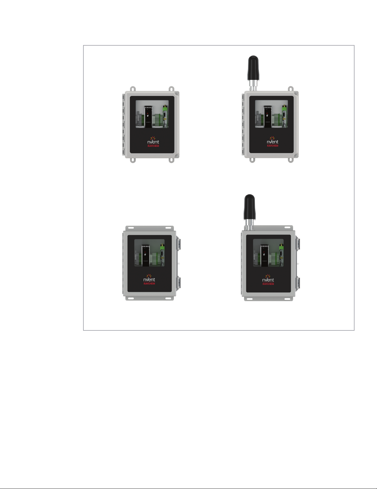
1.1.2 Enclosure Variants
(See Notes 1and 2)
Catalog
Number Part Number Description
10392-100 9200i-E-PC-868-FW
Elexant 9200i 868 MHz Phoenix Contact module in FG
enclosure with window, antenna, and pre-drilled holes for
power (M25) and communications (M20)
10392-101 9200i-E-PC-868-FW-EXT
Elexant 9200i 868 MHz Phoenix Contact module in FG
enclosure with window, external antenna connection, and
pre-drilled holes for power (M25) and communications (M20)
- antenna & coax sold separately
10392-102 9200i-E-PC-868-SW
Elexant 9200i 868 MHz Phoenix Contact module in SS
enclosure with window, antenna, and pre-drilled holes for
power (M25) and communications (M20)
10392-103 9200i-E-PC-868-SW-EXT
Elexant 9200i 868 MHz Phoenix Contact module in SS
enclosure with window, external antenna connection, and
pre-drilled holes for power (M25) and communications (M20)
- antenna & coax sold separately
10392-104 9200i-A-PC-900-FW Elexant 9200i 900 MHz Phoenix Contact module in FG
enclosure with window and antenna
10392-105 9200i-A-PC-900-FW-EXT
Elexant 9200i 900 MHz Phoenix Contact module in FG
enclosure with window and external antenna connection -
antenna & coax sold separately
10392-106 9200i-A-PC-900-SW Elexant 9200i 900 MHz Phoenix Contact module in SS
enclosure with window and antenna
10392-107 9200i-A-PC-900-SW-EXT
Elexant 9200i 900 MHz Phoenix Contact module in SS
enclosure with window and external antenna connection -
antenna & coax sold separately
10392-108 9200i-A-PC-024-FW
Elexant 9200i 2.4GHz Phoenix Contact module in FG
enclosure with window
and antenna
10392-109 9200i-A-PC-024-FW-EXT
Elexant 9200i 2.4GHz Phoenix Contact module in FG
enclosure with window and external antenna connection -
antenna & coax sold separately
10392-110 9200i-A-PC-024-SW
Elexant 9200i 2.4GHz Phoenix Contact module in SS
enclosure with window
and antenna
10392-111 9200i-A-PC-024-SW-EXT
Elexant 9200i 2.4GHz Phoenix Contact module in SS
enclosure with window and external antenna connection -
antenna & coax sold separately
10392-112 9200i-E-PC-024-FW
Elexant 9200i 2.4GHz Phoenix Contact module in FG
enclosure with window, antenna, and pre-drilled holes for
power (M25) and communications (M20)
10392-113 9200i-E-PC-024-FW-EXT
Elexant 9200i 2.4GHz Phoenix Contact module in FG
enclosure with window, external antenna connection, and
pre-drilled holes for power (M25) and communications (M20)
- antenna & coax sold separately
10392-114 9200i-E-PC-024-SW
Elexant 9200i 2.4GHz Phoenix Contact module in SS
enclosure with window, antenna, and pre-drilled holes for
power (M25) and communications (M20)
10392-115 9200i-E-PC-024-SW-EXT
Elexant 9200i 2.4GHz Phoenix Contact module in SS
enclosure with window, external antenna connection, and
pre-drilled holes for power (M25) and communications (M20)
- antenna & coax sold separately
Table 1- Elexant 9200i Enclosure Variants