nVent SCHROFF LHX+ User manual

1
nVent SCHROFF
Cooling Cabinet LHX+
User Manual
Release 1.0
07.04.2021
Doc-No.: 61130-210

2
Schroff GmbH
Langenalber Str. 96-100
75334 Straubenhardt/Germany
schroff.nVent.com
This document is furnished under license and may be used or copied only in accordance with the
terms of such license. The content of this manual is furnished for informational use only, is subject
to change without notice, and should not be construed as a commitment by nVent. nVent
assumes no responsibility or liability for any errors or inaccuracies that may appear in this
document.
Except as permitted by such license, no part of this publication may be reproduced, stored in a
retrieval system, or transmitted, in any form or by any means, electronic, manual, recording, or
otherwise, without the prior written permission of nVent.
All nVent marks and logos are owned or licensed by nVent Services GmbH or its affiliates. All
other trademarks are the property of their respective owners. nVent reserves the right to change
specifications without notice.
Copyright © 2021 nVent
All Rights Reserved.

Date: 2021/04/07
Page: 3 of 47
1Safety................................................................................................................................5
1.1 Intended Use.................................................................................................................5
1.2 Safety instructions of the manufacturer .........................................................................5
1.2.1 Disclaimer.................................................................................................................5
1.3 Safety symbols used in this manual ..............................................................................6
1.4 Safety Information for the Operator...............................................................................7
1.4.1 General notes...........................................................................................................7
1.4.2 Qualification of the personnel ...................................................................................7
1.4.3 Personal protective equipment .................................................................................7
1.5 Safety features..............................................................................................................7
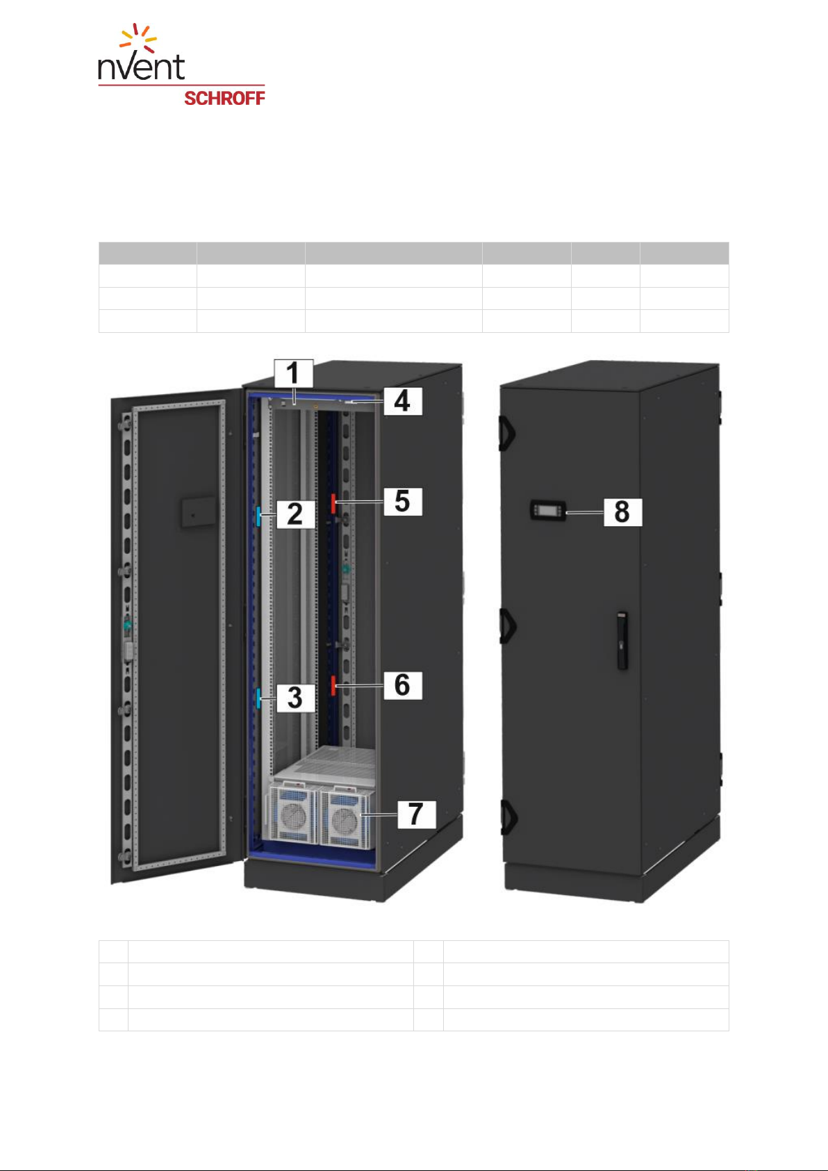
2LHX+ overview.................................................................................................................8
2.1 Functional description .................................................................................................10
2.2 Cooling capacity control..............................................................................................11
3Transport and assembly................................................................................................12
3.1 Safety rules for transport and assembly ......................................................................12
3.2 Unpacking...................................................................................................................13
3.3 Placing the cabinet......................................................................................................14
3.3.1 Lifting the cabinet from the pallet............................................................................15
3.4 Commissioning............................................................................................................16
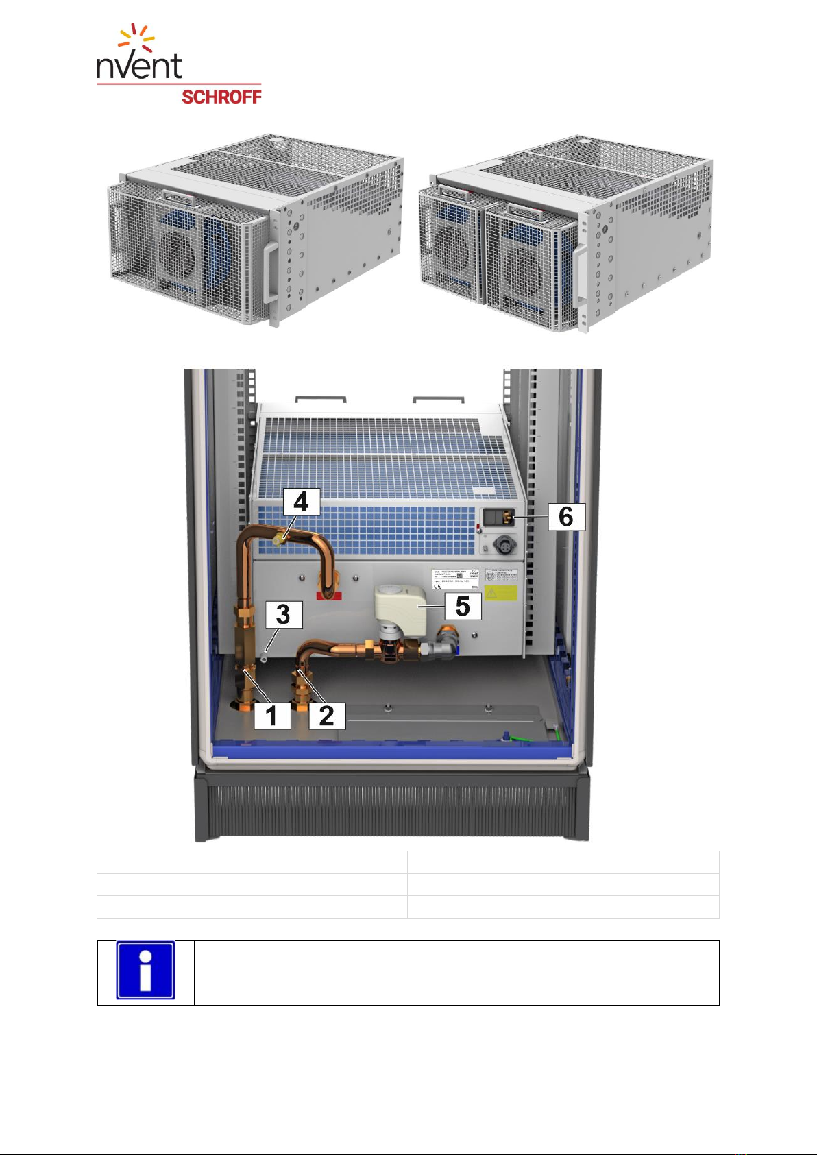
3.4.1 Connection to the cooling water supply...................................................................17
3.4.2 Requirements for the water quality .........................................................................18
3.4.3 Water connection....................................................................................................19
3.5 Bleeding the cooling module .......................................................................................20
3.5.1 Mains connection....................................................................................................21
3.5.2 Mains inputs ...........................................................................................................22
3.6 Connectors controller box ...........................................................................................23
3.6.1 Plug in/Unplug connectors at the controller box......................................................23
3.7 Initial operation............................................................................................................24
4Monitoring and Configuration.......................................................................................25
4.1 Web Interface..............................................................................................................25
4.1.1 Web interface screens............................................................................................25

Date: 2021/04/07
Page: 4 of 47
4.2 Display........................................................................................................................29
4.2.1 Display Overview....................................................................................................30
4.2.2 Display menu..........................................................................................................31
4.2.3 Settings ..................................................................................................................32
5Maintenance...................................................................................................................34
5.1 Fan tray replacement ..................................................................................................34
6Optional water kit...........................................................................................................35
6.1 Installing the water kit..................................................................................................36
7Dismantling, storage and disposal...............................................................................37
7.1 Safety rules for dismantling, storage and disposal.......................................................37
7.2 Dismantling.................................................................................................................38
7.3 Storage .......................................................................................................................38
7.4 Disposal......................................................................................................................38
8Technical data................................................................................................................39
8.1 Scope of delivery.........................................................................................................40
8.2 Spare parts .................................................................................................................42
8.3 Accessoires.................................................................................................................43
8.4 Cooling performance...................................................................................................45
8.5 Air flow........................................................................................................................46
8.7 Noise Level.................................................................................................................47

Date: 2021/04/07
Page: 5 of 47
1 Safety
1.1 Intended Use
The nVent SCHROFF LHX+ cabinets described in this manual represent closed cooling
systems and allow cooling of the electronic components installed in the 19" plane
independently of the ambient or room temperature.
Before commencing operation the cabinet’s cooling modules must be connected to an
external recirculation cooling system (chiller).
Intended use includes compliance with the terms and conditions for assembly, disassembly,
commissioning, operation and maintenance specified by the manufacturer.
1.2 Safety instructions of the manufacturer
1.2.1 Disclaimer
Schroff accepts no liability for any errors in this documentation. To the maximum extent
permissible by law, any liability for damage, direct or indirect, arising from the supply or use
of this documentation is excluded.
Schroff retains the right to modify this document, including the liability disclaimer, at any time
without notice and accepts no liability for any consequences of such alterations.

Date: 2021/04/07
Page: 6 of 47
1.3 Safety symbols used in this manual
In these original operating instructions, warning notices point out residual risks that cannot be
avoided by constructive means when installing or operating the cooling module. The warning
notices are classified according to the severity of the damage occurring and the probability of
its occurrence.
⚠DANGER
Symbol
Short description of the danger
The signal word DANGER indicates an immediate danger.
Non-observance will result in severe injuries or death.
⚠WARNING
Symbol
Short description of the danger
The signal word WARNING indicates a possible danger.
Non-observance can lead to serious injury or death.
⚠CAUTION
Symbol
Short description of the danger
The signal word CAUTION indicates a possible danger.
Non-observance can lead to injuries.
ATTENTION
Short description
The signal word ATTENTION indicates possible damages to equipment.
Non-observance can lead to damage to the device.
Important information

Date: 2021/04/07
Page: 7 of 47
1.4 Safety Information for the Operator
1.4.1 General notes
The operator must comply with all relevant safety regulations for setting up and operating the
nVent SCHROFF LHX+ cabinets, e.g. accident prevention regulations for the operation of
cooling equipment. Furthermore, the installation and connection conditions and the
corresponding instructions in Chapter 3 Transport and installation must be observed.
1.4.2 Qualification of the personnel
Only trained specialists are authorized to carry out assembly, commissioning, completion,
maintenance and service of the LHX+ cabinets or the integrated cooling modules. The
nationally applicable health and safety regulations must also be adhered to.
1.4.3 Personal protective equipment
⚠WARNING
Risk of injury due to insufficient personal protective equipment
If you use the wrong protective equipment or no protective equipment at all,
you could be seriously injured.
- Wear protective equipment adapted to the work processes.
- Check the protective equipment before each use to ensure that it is intact!
- Use only approved protective equipment.
The personnel responsible for installation, maintenance and operation must wear protective
equipment appropriate to the work processes.
The following personal protective equipment is required:
- Safety glasses
- Helmet
- Protective gloves
- Protective boots
1.5 Safety features
The cabinet is equipped with door contact switches (1, 2) to protect the operator and the
equipment from spraying water. When the doors are open, the cooling module is shut off, the
fans are disabled.

Date: 2021/04/07
Page: 8 of 47
2 LHX+ overview
The nVent SCHROFF LHX+ product family are closed electronics cabinets with integrated
air-to-water heat exchangers installed at the bottom of the 19" plane.
The following variants are available at the time of the compilation of this manual:
Part-No.
Type
Height/Width/Depth
Rear door
Display
Gasket
10130-325
LHX+ 5 kW
2000 x 600 x 800 mm
-
-
IP
10130-326
LHX+ 5 kW
2000 x 600 x 1000 mm
x
x
EMC
10130-327
LHX+ 10 kW
2000 x 600 x 1000 mm
-
x
EMC
1
Controller box
5
Warm air temperature sensor top
2
Cold air temperature sensor top
6
Warm air temperature sensor bottom
3
Cold air temperature sensor bottom
7
Cooling module
4
Door contact
8
Display

Date: 2021/04/07
Page: 9 of 47
Cooling module 5 kW
Cooling module 10 kW
1 Water outlet
4 Bleeding valve
2 Water inlet
5 Actuator water valve
3 Condensate drain (10 mm)
6 Fused mains input IEC60320-C14
The cooling modules contain no user serviceable parts inside; the fan trays
are hot swappable.

Date: 2021/04/07
Page: 10 of 47
2.1 Functional description
The cooling system consists of an air loop and a water loop.
The fans of the cooling unit draw warm air from the rear section of the cabinet and into an
air/water heat exchanger. The air is cooled down and then blown into the front area of the
cabinet.
Inside the air/water heat exchanger the heat energy of the warm air is transferred to the
medium of water. The air/water heat exchanger is connected to an external reciprocal chiller
unit (not supplied with the module), where the water is cooled down again.
The water inlet temperature and the cooling water flow and the air flow determine the cooling
capacity of the cooling module.

Date: 2021/04/07
Page: 11 of 47
2.2 Cooling capacity control
Controller Box
1
RJ45 connector Ethernet
5
Air inlet for differential pressure sensor
2
RJ45 connector RS485 (Modbus RTU)
6
Controller box rear view
3
Controller box front view
7
Door contact rear door/rear panel
4
Door contact front door
The LHX+ controller is located together with the differential pressure sensor in a 2 U / 19”
controller box (6) at the top of the cabinet.
The controller drives an electromechanical control valve in the water circuit to regulate the
flow of water through the heat exchanger as a function of the heat load. The control variable
is the data from the cold air temperature sensors.
In order to compensate for temperature stratification, the cold air temperature is measured by
2 temperature sensors at different heights. As control variable the temperature of the lower,
the upper or the average value of these temperature sensors can be used as a reference.
The air flow rate also has an influence on the cooling capacity, the controller can either set
the fan speed to a fixed value of 70 % -100 % or adjust it depending on the differential
pressure.

Date: 2021/04/07
Page: 12 of 47
3 Transport and assembly
3.1 Safety rules for transport and assembly
⚠WARNING
Risk of injury and/or material damage from falling or tipping loads!
When transporting the cabinet with a pallet truck, forklift or crane,
do not step under the suspended load.
Only use approved equipment and slings to lift the cabinet.
During transport and assembly, the corresponding personal
protective equipment must be worn.
The cabinet is top-heavy and can tip over. At least 2 people are
required when moving and unpacking the cabinet
⚠WARNING
Risk of accidents due to insufficiently qualified personnel!
The installation may only be carried out by qualified personnel
who are authorized to do so according to the valid safety
regulations, e.g. by authorized specialized companies or
authorized departments of the company.
When installing the system, the corresponding personal protective
equipment must be worn.
Use eye
protection!
Use hand
protection!
Use foot
protection!
Use head
protection!
The specified personal protective equipment must be used during all assembly and transport
work.
ATTENTION
Risk of condensation forming!
After storage at temperatures below 10 °C, sufficient acclimatization time must be allowed
before the unit is switched on.

Date: 2021/04/07
Page: 13 of 47
3.2 Unpacking
The LHX+ is delivered on a pallet.
Remove any transport material and packaging.
Dispose of the transport and packaging material in an environmentally compliant
manner and in accordance with the applicable local rules and regulations.
Leave the cabinet on the pallet to transport it to its destination.
Check the LHX+ after unpacking for transport damage or other damage.

Date: 2021/04/07
Page: 14 of 47
3.3 Placing the cabinet
⚠WARNING
Risk of injury and/or material damage from falling or tipping loads!
When transporting the cabinet with a pallet truck, forklift or crane,
do not step under the suspended load.
Only use approved equipment and slings to lift the cabinet.
During transport and assembly, the corresponding personal
protective equipment must be worn.
The cabinet is top-heavy and can tip over. At least 2 people are
required when moving and unpacking the cabinet
ATTENTION
Risk of damage!
The cabinet must only be mounted on a flat surface with sufficient load-bearing capacity.
Remove the transport protection for the water connections only after lifting the cabinet from
the pallet.
It is recommended to use lifting eyes and a crane to lift the cabinet from the
pallet.

Date: 2021/04/07
Page: 15 of 47
3.3.1 Lifting the cabinet from the pallet
The following steps describe how to lift the cabinet from the pallet with a forklift truck.
1) Transport the cabinet on the pallet to the installation site and remove the fastening
screws with which the cabinet is fixed on the pallet.
Note: For 800 mm deep cabinets, the fan trays must be removed first.
2) Remove the frontpanels and sidepanels.
3) Adjust the forks to the cabinet width.
4) Lift the cabinet carefully from the pallet without damaging the leveling feet (1) and the
transport protection (2). Leave enough space (3) between the cabinet and the forklift
5) Level the cabinet at the installation site
using the leveling feet (1).
6) Remove the transport protection (2) for
the water connections.

Date: 2021/04/07
Page: 16 of 47
3.4 Commissioning
The cabinet is completely wired and preconfigured. After connecting the power and water
supply, it can be put into operation.
ATTENTION
Damage due to leaking water!
Fittings may have loosened due to transport or during installation.
Before commissioning, all fittings of the water circuit must be checked and tightened if
necessary.
The leaktightness must be checked during filling of the system.
ATTENTION
Damage due to condensation and spraying water!
The cabinet doors must be closed for operation. If the cooling module is operated in an
open cabinet, condensation water will be produced around the heat exchanger, which is
distributed by the fans in the enclosure and can damage the electronics components.
The cabinet is equipped with door contact switches. When the doors are
open, the cooling module is shut off, the fans are disabled.
To ensure proper function and cooling performance, the front 19" plane must
be sealed off from the rear part of the cabinet by suitable air baffle plates and
seals.

Date: 2021/04/07
Page: 17 of 47
3.4.1 Connection to the cooling water supply
ATTENTION
Outflow of cooling water can cause damage!
Connection to the cooling water supply should be carried out by a refrigeration
engineer or suitably trained plumber.
It must be ensured that suitable structural measures (leak sensor, automatic shut-
off valves) prevent damage to surrounding components in the event of a leak or
defect. These measures depend on the installation location or the structural
conditions and are the responsibility of the installer or system designer.
Ensure that the water supply pressure does not exceed the unit rating.
Notes on the water connection:
The cooling infrastructure to which the unit is connected (the external
water loop) must be appropriately dimensioned by the system
designer, taking into consideration the available pump pressure and
type, the nominal pipe diameters and the pressure loss expected in
the load circuit (the cooling module).
To avoid a pressure drop in the system, the water pipes should be
kept as short as possible.
The behavior of the materials used in the cooling module with the
materials of the external water circuit must be observed in order to
avoid corrosion damage!
When creating the on-site piping, contamination in the line system
must be avoided, or the lines must be flushed before connecting the
cooling module.
Shut-off and drain valves on each cabinet as well as a central water
filter and air separator are mandatory.

Date: 2021/04/07
Page: 18 of 47
3.4.2 Requirements for the water quality
ATTENTION
Risk of corrosion!
If aluminum is used in the external water circuit, there is a risk of corrosion.
To avoid electrochemical corrosion, the compatibility of the materials used in the
cooling module with those of the external cooling circuit must be observed.
The type and dosage of a suitable anticorrosive or antifreeze agent depends on the
structural environment and the external recooling system and must be determined
individually by the plant planner.
The following materials are used in the cooling module:
Aluminum
Brass
Copper
Stainless steel
To ensure trouble-free operation of the cooling module, the following water quality
requirements must be met.
(see also VDI 3803 / ASHRAE: Liquid cooling guidelines for Datacom equipment centers,
second edition).
Electrical conductivity:
25 mS/m - 100 mS/m at 25 °C /77 °F
Hydrogen concentration:
7,5 - 8,5 (ph-value) at 20 °C /68 °F
Chloride:
< 50 mg/l / 50 ppm
Total Hardness:
> 3 °dH < 8 °dH
Colony-forming units:
< 1000 CFU/ml
Appearance:
clear
Colour:
colourless

Date: 2021/04/07
Page: 19 of 47
3.4.3 Water connection
Cabinet bottom view
The water return (3) and supply (4) connections are located under the bottom plate of the
cabinet. During transport, the water connections are protected by an angled sheet metal (2).
To remove the sheet metal and access the water connections you have to remove the lower
side panels (1).
The required connection nominal widths and the position of the connections
at the cabinet’s bottom plate can be found in the drawings in the appendix to
this manual.
Condensate drain:
The bottom of the cooling module is designed as a condensate tray with a 10 mm hose
connection (5) at the rear side. By default, the hose connection is closed by a plug.
Especially at low water inlet temperatures it is recommended to realize the condensate drain
on site via the hose connection (5).
Connect the water supply, water return and condensate drain according to the drawings in
the appendix to this operating manual.

Date: 2021/04/07
Page: 20 of 47
3.5 Bleeding the cooling module
ATTENTION
Risk of damage!
To avoid damage, the cooling module must be disconnected from the power supply during
bleeding.
Before commissioning, the device must be bleeded.
Have the refrigeration engineer/plumber open the water flow to the cabinet.
Connect a tube to the bleeding valve (1) and place it in a container with a capacity of
at least 1.5 litres.
Open the actuator (2) manually with a 3 mm hexagonal key. (Turn it to position “1”)
Close the return valve and open the supply valve (Stopcocks in the raised floor)
Open the bleeding valve (1) carefully using a four-sided Allen key.
Allow any air to escape. When water begins to pass, close the bleeding valve.
This manual suits for next models
3
Table of contents
Popular Indoor Furnishing manuals by other brands

Signature Design by Ashley
Signature Design by Ashley 1090012 manual

Whittier Wood Furniture
Whittier Wood Furniture McKenzie 1180GACg Assembly instructions

Politorno
Politorno Verona Desk 1055 Assembly instructions

Multimo
Multimo A 751 Assembly instructions

Ceriotti
Ceriotti Easy 7216 quick start guide

Furniture of America
Furniture of America Gianna CM3829BN Assembly instructions

pakoworld
pakoworld Jane 055-000130 Assembly manual

IMG
IMG Soho Chair Assembly instructions

Safavieh Furniture
Safavieh Furniture FOX2565A quick guide

Seaside Casual
Seaside Casual 44 SYM Table Assembly instructions

Bestar
Bestar 26167-1117-1217 Assembly instructions

modway
modway EEI-2221 Assembly instructions