SAFETY WARNINGS AND PRECAUTIONS
Complete Installation Guide
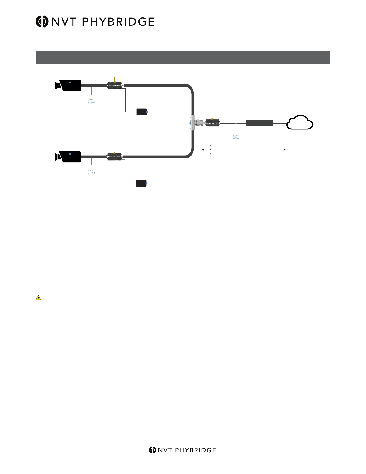
Model NV-EC1701U
EoC Ethernet over Coax Transceiver
with PoE, PoE+, or High Power PoE
Access to the interior of this unit shall be made only by
a qualied technician.
To ensure adequate cooling of the equipment, a 2-inch
unobstructed space must be provided around all sides
of the unit.
To prevent the risk of shock or re hazard, replace fuse
with same type and rating.
Der Zugang ins Innere des Gerätes ist nur einem
fachlich qualizierten Techniker gestattet.
Um die Kühlung des Gerätes nicht zu beeinträchtigen,
ist es notwendig, an allen Seiten des Gerätes ca 5 cm
Raum zu lassen.
Zur Vermeidung der Stromschlag-und Feuergefahr
beim Auswechseln Sicherungen des gleichen Typs und
der gleichen Nennleistung einsetzen.
Seul un spécialiste doit avoir accès l’appareil.
An de ne pas nuire au processus de refroidissement, il
est nécessaire de laisser un espace d’environ 5 cm de
chaque côté de l’appareil.
An d’éviter tout risque d’incendie ou d’électrocution,
remplacez les fusibles par des fusibles de même type
et de même ampérage.
El acceso al interior de esta unidad deberá ser realizado
únicamente por un técnico cualicado.
Para asegurar un enfriamiento adecuado del equipo, se
debe proporcionar un espacio sin obstrucciones de 2
pulgadas alrededor de todos los lados de la
unidad.
Para evitar el riesgo de choque o peligro de incendio,
reemplace el fusible con el mismo tipo y clasicación.
L’accesso all’interno di questa unità `deve essere
eettuata solo da un tecnico qualicato.
Per garantire un adeguato rareddamento
dell’apparecchiatura, uno spazio libero da 2 pollici deve
essere fornita intorno a tutti i lati dell’unità.
Per evitare che la prevenzione del rischio di scossa o
di pericolo di incendio, sostituire il fusibile con lo stesso
tipo e valore.
Достъп до вътрешността на този уред трябва да се
извършва само от квалифициран техник.
За да се осигури подходящо охлаждане на
оборудването, трябва да се осигури 2-инчово
свободно пространство около всички страни на
устройството.
За да предотвратите опасност от удар или
пожар, сменете предпазителя със същия тип и
квалификация.
Juurdepääs interjööri selle üksuse tehakse ainult
kvalitseeritud tehnik.
Jahutuse tagamiseks seadme, 2-tolline vaba ruum
peab olema ümber kõik küljed üksus.
Selleks, et vältida riski ning tulekahjuoht, vaheta kaitse
sama tüüpi ja hinnang.
Η πρόσβαση στο εσωτερικό της μονάδας πρέπει να
γίνεται μόνο από εξειδικευμένο τεχνικό.
Για να εξασφαλιστεί η κατάλληλη ψύξη του εξοπλισμού,
πρέπει να υπάρχει ένας ελεύθερος χώρος 2 ιντσών
γύρω από όλες τις πλευρές της μονάδας.
Για να αποφύγετε τον κίνδυνο κρούσης ή πυρκαγιάς,
αντικαταστήστε την ασφάλεια με τον ίδιο τύπο και την
ίδια βαθμολογία.
Piekļuve interjera šīs vienības veic tikai kvalicēts
tehniķis.
Lai nodrošinātu pietiekamu dzesēšanu iekārtu, 2 collu
aizsegts telpu jānodrošina ap visām pusēm vienības.
Lai novērstu risku, ka trieciena vai ugunsgrēka briesmas,
nomainīt drošinātāju ar tāda paša veida un reitingu.
Prieiga prie šio įrenginio viduje, turi būti atlikti tik
kvalikuotas specialistas.
Siekiant užtikrinti tinkamą aušinimą įranga, 2 colių
užgriozdinti erdvę turi būti pateikta apie visus įrenginio
pusių.
Siekiant užkirsti kelią šoko ar gaisro pavojus riziką,
pakeiskite saugiklį su tos pačios rūšies ir įvertinimas.
A készülék belsejét csak szakképzett szakember
végezheti.
A berendezés megfelelő hűtésének biztosítása
érdekében egy 2 hüvelykes, akadálytalan helyet kell
biztosítani a készülék minden oldalán.
Az ütésveszély vagy a tűzveszély elkerülése érdekében
cserélje ki az azonos típusú és minősített biztosítékot.
Toegang tot het interieur van dit toestel wordt alleen
door een gekwaliceerde technicus uitgevoerd.
Om een adequate afkoeling van de apparatuur te
garanderen, moet een 2-inch vrijstaande ruimte rondom
alle kanten van het apparaat worden aangebracht.
Om het risico op schokken of brandgevaar te voorkomen,
vervang de zekering met hetzelfde type en de waarde.
Tilgang til det indre av denne enheten skal kun utføres
av en kvalisert tekniker.
For å sikre tilstrekkelig kjøling av utstyret, må det være
2 tommers uhindret plass rundt alle sider av enheten.
For å unngå fare for støt eller brannfare, bytt sikring
med samme type og karakter.
Dostęp do wnętrza tego urządzenia wykonuje tylko
wykwalikowany technik.
W celu zapewnienia odpowiedniego chłodzenia
urządzenia, wokół wszystkich stron urządzenia musi
być umieszczona 2-calowa przestrzeń bez przeszkód.
Aby uniknąć ryzyka porażenia prądem lub pożaru,
wymień bezpiecznik na ten sam typ i poziom.