manuals.online logo
Brands
  1. Home
  2. •
  3. Brands
  4. •
  5. O.S. engine
  6. •
  7. Engine
  8. •
  9. O.S. engine MAX-37SZ-H RING Setup guide

O.S. engine MAX-37SZ-H RING Setup guide

It is of vital importance, before attempting to operate
your engine, to read the general 'SAFETY INSTRUCTIONS
AND WARNINGS' in the following section and to strictly
adhere to the advice contained therein.
Also, please study the entire contents of this
instruction manual, so as to familiarize yourself with
the controls and other features of the engine.
SAFETY INSTRUCTIONS AND WARNINGS ABOUT YOUR O.S.ENGINE
The advice which follows is grouped under two
headings according to the degree of damage or
danger which might arise through misuse or neglect.
WARNINGS
NOTES
These cover events which might involve serious
(in extreme circumstances, even fatal) injury.
These cover the many other possibilities, generally less
obvious sources of danger, but which, under certain
circumstances, may also cause damage or injury.
WARNINGS
ENGINE PARTS NAME
Remember that your engine is not a " toy ", but a
highly efficient internal-combustion machine whose
power is capable of harming you, or others, if it is
misused. As owner, you, alone, are responsible for
the safe operation of your engine, so act with
discretion and care at all times. If at some future
date, your O.S. engine is acquired by another
person, we would respectfully request that these
instructions are also passed on to its new owner.
NOTES
Never operate your engine in an enclosed space.
Model engines, like automobile engines, exhaust
deadly carbon-monoxide. Run your engine only
in an open area.
Never touch, or allow any object to come
into contact with, the rotating parts.
Model engine fuel is also highly flammable.
Keep it away from open flame, excessive
heat, sources of sparks, or anything else
which might ignite it. Do not smoke or allow
anyone else to smoke, near to it.
Model engines generate considerable
heat. Do not touch any part of your
engine until it has cooled. Contact with
the muffler (silencer), cylinder head or
exhaust header pipe, in particular, may
result in a serious burn.
Model engine fuel is poisonous. Do not allow
ittocomeintocontactwiththeeyesormouth.
Always store it in a clearly marked container
and out of the reach of children.
This engine was designed for model helicopters.
Do not attempt to use it for any other purpose.
Mount the engine in your model securely, following
the manufacturers' recommendations, using appropriate
screws and locknuts.
Install an effective silencer (muffler). Frequent close
exposure to a noisy exhaust (especially in the case of
the more powerful high-speed engines) may eventually
impair your hearing and such noise is also likely to
cause annoyance to others over a wide area.
Check the linkage to the throttle arm before each
flight.
Avoid sudden high r.p.m. immediately after the
engine is started, as the clutch will engage and you
may be struck by the rotor.
After starting the engine, carry out any needle-valve
readjustments after stopping the rotor by closing the
throttle to the lowest r.p.m..
Stop the engine before attempting to make other
adjustments to the carburetor.
Use an electric starter. The wearing of safety
glasses is also strongly recommended.
Press the rotor head down securely.
Take care that the glow plug clip or battery leads do
not come into contact with rotating parts.
Adjust the throttle linkage so that the engine stops
when the throttle stick and trim lever on the
transmitter are fully retarded. Alternatively, the
engine may be stopped by cutting off the fuel
supply. Never try to stop the engine physically.
Take care that loose clothing (ties, shirt sleeves,
scarves etc.) do not come into contact with the rotor.
Do not carry loose objects (such as pencils, screwdriv-
ers, etc.) in a shirt pocket from where they could fall
through the rotor disc.
For their safety, keep all onlookers (especially small
children) well back (at least 20 feet or 6 metres) when
preparing your model for flight. If you have to carry the
model to the take-off point with the engine running, be
especially cautious. Hold the rotor securely and keep
well clear of spectators.
Warning! lmmediately after a glowplug-ignition
engine has been run and is still warm, conditions
sometimes exist whereby it is just possible for the
engine to restart when turned over WITHOUT the
glowplug battery being reconnected. Remember this
if you wish to avoid the risk of accidents.
Notes on installing cooling fan and clutch
Do not use a tool which
locks piston when installing
a cooling-fan and clutch, or
top of the piston may be
damaged. Also, do not insert
a screw driver or the similar
into the exhaust port.
Do not grip the engine mounting beams with a
vise, or the crankcase will be distorted which
will result in engine breaking.
Vise
NOTES WHEN APPLYING AN ELECTRIC STARTER
Because of this initial tightness, a standard
electric starter may have difficulty in rotating the
engine when cold, before it has been adequately
run-in. In this case, use a high-torque type starter.
Do not over-prime. This could cause a hydraulic
lock and damage the engine on application of the
electric starter.
If over-primed, remove glowplug, close needle-valve
and apply starter to pump out surplus fuel. Cover
the head with a rag to prevent pumped out fuel
from getting into your eyes.
F
J
J
F
28
34
27
33
A
B
90°
90°
A=B
Linking the throttle servo to the carburetor
Link the throttle servo to the carburetor using
the throttle lever supplied. Throttle control rod
A and B should be equal length. Set the
linkage so that the servo output lever and
throttle lever are parallel when the throttle
stick on the transmitter is at middle position.
Installing hole intervals on the F lever and on
the J lever are different. Decide the lever to
use according to the servo used. Be sure to
cut off another lever to avoid any interference.
INTRODUCTION
Throttle lever is not installed on the carburetor
when the engine leaves the factory.
Install it before using the engine.
NOTE
STANDARD ACCESSOIES
Glow Plug No.8
Throttle Lever Assembly
This is a high performance engine designed for
small-sized radio-controlled helicopters.
Since the mounting bolt pattern of the engine as
well as silencer is the same as those of the 32SX-H,
it can be directly replaced with the 32SX-H and most
of other 32-39 size engines. This powerful engine is
suitable for sport flight as well as 3D flight.
With some models, needle interferes the body and
working on the body to avoid this would be required.
Needle Valve
Fuel Inlet
Mixture Control Valve
Throttle Lever
Rotor Guide Screw
Heatsink Head
Carburetor
Type 20M
Crankshaft
Propeller nut
Crankcase
Glowplug
Beam Mount
Cover Plate
Thrust Washer
Carburetor Gasket
Items necessary for starting
Tools, accessories, etc.The following items are necessary
for operating the engine.
BEFORE STARTING
Battery leads
1.5 volt dry cell
These are used to conduct current from
the battery to the glowplug. Basically, two
leads, with clips, are required, but, for
greater conve-nience, twin leads with
special glowplug connectors, as shown on
the right, are commercially available.
Battery leads
glowplug Igniter
The power source for heating the glowplug may be
either a large heavy-duty 1.5volt dry cell, Ni-cd battery
or glowplug Igniter.
Glowplug battery
600928300000
Beam Mount
It is recommended to use
Crankshaft Clamp 37 (Code
No.71530600) available as an
optional tool.
O.S. No.8 glowplug is
supplied with the engine
MAX-37SZ-H RING
Make sure glowplug element glows
bright red inside room or shadow.
Battery leads
In case of 1.5volt dry cell
12V Battery
Starter
Electric starter and starter battery
An electric starter is recommended
for starting.
Hexagon starting shaft
This shaft mounted on an electric starting motor
is driven into the shaft cup to turn the engine.
Select, by practical tests, the most suitable fuel from among
the best quality fuels available in your country for helicopter
use. For the best throttle response, a fuel containing 10% to
30% nitromethane is preferable. Lubricants may be either
castor-oil or a suitable synthetic oil (or. a blend of both)
provided that they are always of top quality. For consistent
performance and long engine life, it is essential to use fuel
containing AT LEAST 18% lubricant by
volume. Some fuels containing coloring
additives tend to deterriorate and may
adversely affect running qualities. If in
doubt compare to a fuel known to be good.
Fuel
Alternatively, one of the purpose-made
manual or electric fuel pumps may be
used to transfer fuel directly from your fuel
container to the fuel tank.
Manual
Electric
It is recommended to install a good
in-line filter between the fuel tank and
carburetor to prevent entry of foreign
matter into the carburetor.
Fuel Filter
Fuel Pump
Silicone Fuel Line
TOOLS
Screwdriver
Necessary for engine installation.
1.5mm, 2mm, 2.5mm, 3mm
Necessary for carburetor adjustments.
No.1, No.2, etc
Phillips Screwdriver
No.1, No.2, etc.
Socket Drivers
5mm, 5.5mm, 7mm
Hex Drivers
8mm
End Wrenches
8mm, 13mm, 14mm, etc.
Needle Nose Pliers
Long Socket Wrench With Plug Grip
INSTALLATION OF THE ENGINE
Front view
CORRECT
Side view
Top surfaces are in the same plane.
Re-align the surfaces as necessary
INCORRECT
Top surfaces are not
in the same plane. Top surfaces are not in the
same plane.
Engine does not rest firmly.
Make sure that only the under-surfaces
of the engine’s mounting lugs are in
contact with the engine mount.
INSTALLING THE GLOWPLUG
Install washer on glowplug and
insert carefully into Heatsink-head,
making sure that it is not
cross-threaded before tightening
firmly.
Glow plug
Washer
Throttle lever is not installed on the carburetor when the
engine leaves the factory. Install it before using the
engine referring to the sketch below.
INSTALLATION OF THE THROTTLE LEVER
INSTALLATION OF THE STANDARD ACCESSORIES
Throttle Lever
Retaining Screw
Washer
CARBURETOR CONTROLS
With a fixed-wing model, power failure is rarely a
serious threat to the safety of the aircraft since it can
usually glide down to a safe landing. In a helicopter, on
the other hand, it is vitally imporant that the engine
keeps running and that there is a quick and reliable
response to the throttle in order to ensure safe ascent
and descent of the model.
The Needle Valve:
When set to produce maximum power at full throttle,
this establishes the basic fuel/air mixture strength.
This is then maintained by the carburetor's automatic
mixture control system to cover the engine's
requirements at reduced throttle settings.
The Mixture Control Valve
For adjusting the mixture strength at part-throttle and
idling speeds, to obtain steady idling and smooth
acceleration to medium speeds. The Mixture Control
Valve has been factory set for the approximate best
result. First, run the engine as received, and
re-adjust the Mixture Control Valve only when
necessary.
Two adjustable controls are provided on this carburetor.
REALIGNMENT OF MIXTURE CONTROL VALVE
In the course of making carburetor adjustments, it is
just possible that the Mixture Control Valve may be
inadvertently screwed in or out too far and thereby
moved beyond its effective adjustment range.
Its basic setting can be reestablished as follows :
Mixture Control Valve
Carburetor Body
First rotate the Mixture
Control Valve until its slotted
head is flush with the
carburetor body. Then screw
the valve in exactly 1 turn.
This is the standard position.
0.5mm
As shown in the sketch, the carburetor has graduation
marks. When the triangle mark on the carburetor rotor
meets the most right mark, throttle is fully closed. When
the triangle mark meets the top mark, throttle is fully
open. The range is approximately 80 degrees. You may
use other three marks as the reference marking of
throttle opening to your preference when hovering.
WARNING!
Never try to check the triangle mark position while
the engine is running and rotor is rotating, or you
may be hit by rotating rotor which results in serious
injury. Stop the engine and rotor before checking
the triangle mark position.
Carburetor Rotor
Carburetor Body
Fully closed position
Fully opened position Approx.
GRADUATIONS ON THE CARBURETOR BODY
Be sure to use an electric starter to start the engine.
Fill the fuel tank with fuel. When filled, prevent the
fuel from flowing into the carburetor with a
commercially available fuel stopper, etc. Release
the stopper before starting the engine.
1.
2.
Starting procedure is as follows:
Glow Plug Igniter
Pliers
Element glows when energized.
Replace the plug when the
element does not glow or is
burnt out.
Make sure that plug element glows red, and install
the plug in the cylinder head.
Be sure to use a muffler pressurized fuel feed. Use
the same fuel as you intend to employ for actual
operation of your model.
STARTING
Close
Open
1.
2.
3.
Opening and closing of the Needle-Valve
Turn the needle clockwise to
close the needle-valve, and turn
the needle counter-clockwise to
open the needle-valve as shown
in the sketch.
Opening the needle-valve
Firstly, turn the needle clockwise slowly until it
stops. The position it stops is the fully closed
position of the needle-valve. Make note this position
for reference..
Open the needle-valve 1.5 turns.
Preparation of the starter
Install the starting shaft to the
starter securely. Poor installation
swings the starting shaft, which is
dangerous.
4.
5.
6.
Checking the rotating direction of the starter
Make sure that the starter rotates
to the direction shown in the
sketch. If the direction is reverse,
reverse the leads on battery.
Inserting the starter shaft
Insert the starting shaft into the
shaft cup securely.
Priming
Without heating the glowplug, open the throttle a
little from the idle position. Turn the engine using
the starter until the fuel is seen to reach carburetor.
Install a filter to the outlet tube of your
refueling container to prevent entry of
foreign matter into fuel tank. O.S. ‘Super
Filters’ (large and small) are available as
optional extras.
O.S. Super Filter (Fuel Can Filter)
Recommended for easy removal and replacement of
the angled and recessed glowplug, the O.S.Long
Socket Wrench incorporates a special grip.
The under-surfaces of all O.S. engine beam mounting
lugs are precision machined flat and exactyly parallel
to the engine's horizontal axis. It is essential that the
engine mounts in the model are also accurately made
and aligned. If they are not, they will cause stress and
distortion within the engine itself, probably resulting in
loss of performance and internal damage.
The recommended screws for securing the engine to
the engine mounts in the model are 3mm or 4-40 steel
Allen type. It is also advisable to use lock washers or
LOCTITE to prevent nuts from loosening.
Make sure that only the under-surfaces of the engine’s
mounting lugs are in contact with the engine mount.
Please note that crankcase volume of the 37SZ-H is a
little larger than the 32SX-H’s. If the crankcase body
touches the mount, chamfer the edges of the mount.
Heatproof silicone tubing of approx. 5mm o.d.
and 2.5mm i.d. is required for the connection
between the fuel tank and engine.
Preparation of starting
Make sure that the transmitter
throttle stick is at the fully closed
position and the throttle trim at
center position, and make sure
that idle-up switch on the
transmitter is off. Hold the rotor
head by hand so that rotor cannot
rotate when the engine is Started.
Also, steady the model with a foot
on the landing-gear skid.
7.
In case the engine does not stop.
Hold the rotor head, and pinch the silicone tube to stop
the fuel supply. If it still does not stop, pull off the fuel
tubing from the carburetor. It is necessary to readjust
the throttle linkage so that the carburetor rotor is fully
closed when the throttle stick and throttle trim on the
transmitter are fully pulled down.
Stopping the engine
Fully pull down the throttle trim on the transmitter.
Starting
Connect the battery to the glowplug and start the
engine by applying the starter. When started,
switch off the starter and withdraw the starting shaft
after making sure the rotation of the starter shaft
stops.
8.
9.
Note:
Make sure that the throttle linkage is made so that
the throttle is fully closed when the throttle lever
as well as trim lever on the transmitter are fully
pulled down.
NOTE:
If the throttle response is poor or the engine stops
due to a temporarily over-rich mixture immediately
after the engine is started, pinch the fuel line for
one or two seconds until the engine r.p.m.
increase and the engine runs steadily.
All internal-combustion engines benefit, to some
degree, from extra care when they are run for the first
few times known as running-in or breaking-in.
This allows the working parts to mate together under
load at operating temperature.
However, because O.S. engines are made with the aid
of the finest modern precision machinely and from the
best and most suitable materrials, only a very short
and simple running-in procedure is required and can
be carried out with the engine installed in the model.
For the first few flights with a new engine i.e. while the
engine is being run-in set the needle-valve for a slightly
rich mixture not excessively rich as this may result in
poor throttle response and cause the engine to stop.
About one half turn open from the nomal setting will
usually suffice.
RUNNING-IN ("Breaking-in")
ADJUSTMENT
A
The following adjustments are approximately correct
when using a fuel containing 18-25% lubricant and
10-30% nitromethane.
Bear in mind that fuels containing relatively large
percentages of power-boosting nitromethane operate
at richer mixture settings than are needed for mild
fuels and will, therefore, require the Needle Valve to
be readjusted accordingly. The type and percentage of
lubricant used is also a factor here, as noted later in
these instructions.
This carburetor is not equipped with a throttle
stop screw. Instead, idle speed is adjusted by
means of the throttle trim lever on the transmitter.
This enables the full r.p.m. range, from idling to full
power, to be controlled by the throttle stick, and
then allows the engine to be stopped, from the
transmitter, by closing the throttle completely with
the trim lever.
As a safety measure, first check the transmitter
controls, including the throttle stick and trim lever
positions, and hold the main rotor securely before
starting the engine.
B
Set up the throttle linkage as follows:
With the transmitter throttle trim lever fully retarded,
adjust the throttle servo linkage so that the throttle
rotor is (a) fully open when the transmitter throttle
stick is fully advanced and (b) fully closed (i.e.
engine stopped) when the stick is fully retarded.
The idle speed is then set by advancing the throttle
trim lever to the point where the engine runs,
steadily and reliably,at the desired idle speed.
lf, at this time, the engine is slow to pick up and
produces an excess of exhaust smoke, the mixture
is too rich. Correct this condition by turning the
Mixture Control Valve clockwise. lf the mixture is
extremely rich, engine rpm will become unstable :
opening the throttle will produce a great deal of
smoke and rpm may drop suddenly or the engine
may stop. This condition may also be initiated by an
excessively prolonged warming-up period.
lf, on the other hand, the mixture is too Iean, this wiIl
be indicated by a marked lack of exhaust smoke
and a tendency for the engine to cut out when the
throttle is opened. ln this case, turn the Mixture
Control Valve counter-clockwise to enrich the
mixture.
D
E
Warm the engine by allowing it to idle for about 30
seconds. If the engine stops, advance the throttle
trim lever slightly to increase the idle rpm. Then
open the throttle sufficiently to 'float' the model
above the ground.
C
Hover the model and actuate the throttle to observe
response over the medium speed range. lf the
engine smokes excessiveIy and throttle response is
poor, the mixture is too rich ; in which case, land
the model and turn the Needle Valve clockwise. Do
not close the NeedIe Valve too much, keeping it a
little on the rich side at this stage.
lf, on the other hand, hovering is not stable and
response to the throttIe is over-sensitive, or if the
engine tends to overheat, this indicates that the
mixture is too lean and should be corrected by
turning the Needle Valve counter-clockwise.
H
I
Turn the Mixture Control Valve 15 degrees at a
time.
Having provisionally set the idle mixture, the next
step is to adjust the mixture for hovering flight.
F
G
LNow adjust the Needle Valve to achieve the best
performance when the model is flying at full throttle.
lf, at full throttle, acceleration is poor, the exhaust
unduly smoky and the model fails to reach
expected straight line speed, the mixture is too rich
and the Needle Valve setting will need to be
reduced. lf, however, after smoothly acceIerating to
satisfactory high-speed straight and level flight,
power is lost when the model is puIled up into a
climb, the mixture is too lean. ln this case, land the
model immediately and readjust Needle Valve to a
richer setting.
M
NFor helicopters, good throttle response at medium
r.p.m. (e.g.hovering speeds) is most important, since
this is a power range widely used in helicopter flight.
The optimum fuel/air mixture strength at medium
speeds is dependent on obtaining balanced
adjustment of both the Needle Valve and the Mixture
Controlof both the Needle Valve and the Mixture
Control Valve. lf both controls are already at their
optimum setting, some modification to these settings
may be necessary to achieve satisfactory mid-range
throttle response, but such readjustments should
onIy be made within the range where idle reliability
and high-speed performance are not unduly
compromised. Readjustments should therefore be
carried out as follows:
After about 10 seconds of idling, open the throttle to
'float' the model. lf the transition is smooth, the idle
mixture is O.K. If the symptoms of either rich or Iean
running are observed, readjust the Mixture Control
Screw accordingly.
K
When satisfactory hovering flight has been achieved,
land the modeI again and re-check the engine's idle
qualities.
J
Now re-check hovering performance and, if necessary,
fine-tune the mixture for hovering flight.
lf, on the other hand, the response to mid-range
throttle movement is too sensitive (indicating a lean
mid-range mixture), turn the Needle Valve 2 or 3
clicks counter-clockwise or turn the Mixture Control
Valve 1-3 degrees counter-clockwise.
Throttle response at hovering speeds is aIso affected
by the reIationship of the main rotor pitch angle to
throttle opening. If the optimum mid-range throttle
response cannot be obtained by the carburettor
adjustments described above, try adjusting the
helicopter's pitch control characteristics.
Q
P
Olf the mid-range throttle response is not rapid and
positive (indicating a rich mid-range mixture), turn
the Needle Valve 2 or 3 clicks clockwise, or turn the
Mixture Control Valve 1-3 degrees cIockwise.
SUBSEQUENT READJUSTMENTS
Once the engine has been run-in and the carburetor
controls properly set up, it should be unnecessary to
alter the mixture settings, except to make minor
adjustments to the Needle Valve occasionally, to take
account of variations in climatic condisitions.
The use of a different fuel, however, particularly one
containing more, or less, nitromethane and / or a
different type or proportion of lubricating oil, is likely to
call for some readjustment of the Needle-Valve.
Remember that, as a safety measure, it is advisable to
increase the Needle Valve opening by an extra
half-turn counter-clockwise, prior to establishing a new
setting. The same applies if the silencer type is
changed. A different silencer may alter the exhaust
pressure applied to the fuel feed and call for a revised
Needle-Valve setting.
The use of a different glowplug, or changes to the
mainrotor and its pitch angles may also require
compensating carburetor readjustments.
CARBURETOR CLEANLINESS
The correct functioning of the carburetor depends on its
small fuel orifices remaining clear. The minute particles
of foreign matter that are present in any fuel can easily
partially obstruct these orifices and upset mixture
strength so that engine performance becomes erratic
and unreliable. It is recommended that fuel is passed
through a filter when the tank is filled and that a good
in-line filter is installed between the fuel tank and
carburettor and, furthermore, that this filter is frequently
cleaned to remove dirt and lint that accumulates on the
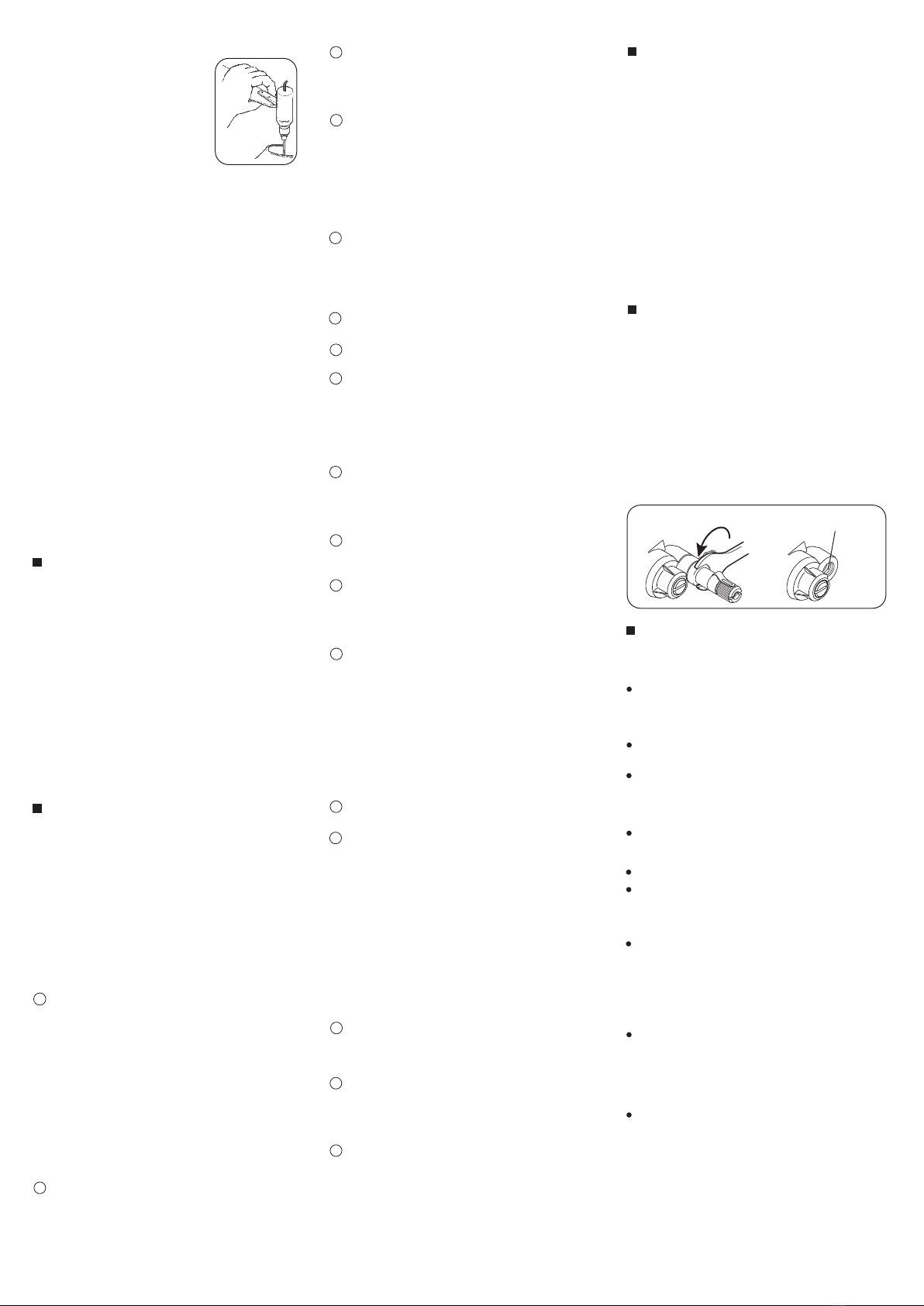
filter screen. Finally, occasionally remove the
needle-valve holder from the carburetor as shown in
Photo and extract any remaining foreign matter that
may have lodged in the location shown in right.
Remove this with
an 8mm spanner
Dirt and fbrous matter
mostly accumulate here
CARE AND MAINTENANCE
Please pay attention to the matters described
below to ensure that your engine serves you well
in regard to performance, reliability and long life.
As previously mentioned, it is vitally important to
avoid operating the engine in conditions where dust,
disturbed by the propeller, may be deposited on the
engine and enter its working parts.
Remember to keep your fuel container closed to
prevent foreign matter from contaminating the fuel.
Install a fuel filter to prevent foreign matter in
the fuel container from entering the fuel tank. O.S.
Super Filters (L) and (S) are available as optional
extras.
Install an in-line fuel filter between the tank and
carburetor to prevent foreign matter in the tank from
entering the carburetor.
If these precautions are neglected, restriction of fuel
flow may cause the engine to cut out, or the fuel/air
mixture to become too lean causing the engine to
overheat.
Clean these filters periodically.
The use of modern high-performance alcohol based
model engine fuels, while promoting cooler running,
improved anti-detonation combustion and increased
power, have the disadvantage of causing corrosion
due to the acid by-products of combustion.
The use of nitromethane in the fuel can also
contribute to the problem.
Do not close the needle-valve and mixture control
valve too far as this will cause a lean setting and
over heating of the engine. This can, in turn, create
nitromethane oxide leading to internal rusting of the
engine. Always adjust the needlevalve slightly on the
rich side of peak rpm.
Do not leave unused fuel in the engine at the
conclusion of a day’s flying. Accepted practice is to
cut off the fuel supply while the engine is still running
at full throttle, then expel as much fuel residue as
possible by turning the engine over 5-10 seconds
with the electric starter.
Finally, inject some after-run oil through the glowplug
hole and turn the engine over several times by hand.
Dimensions (mm)
THREE VIEW DRAWING
ENGINE EXPLODED VIEW ENGINEN PARTS LIST
When the engine is not to be used for some months
(for example, as between flying seasons), a
worthwhile precaution is to remove it from the
airframe and, after washing off the exterior with
alcohol (not gasoline nor kerosene), remove
carefully the carburetor with intake pipe, glow plug
and all silicone tubing and put them safely aside.
Then, immerse the engine in a container of alcohol.
Rotate the crankshaft while the engine is immersed.
If foreign matter is visible in the alcohol, rinse the
engine again in clean alcohol. Finally, shake off and
dry the alcohol ,and inject some after-run oil in the
glowplug hole and rotate the crankshaft several
times by hand. Reinstall the carburetor with intake
pipe and glowplug on the engine and keep it in a dry
place after putting in a vinyl bag.
Type of screw
C…Cap Screw N…Round Head Screw
The specifications are subject to alteration for improvement without notice.
Heatsink Head
Cylinder Liner
Piston Ring
Piston
Piston Pin
Piston Pin Retainer (2pcs.)
Connecting Rod
Carburetor Complete (20M)
Propeller Nut
Thrust Washer
Crankshaft Bearing (Front)
Crankcase
Crankshaft Bearing (Rear)
Crankshaft
Gasket Set
Cover Plate
Screw Set
Throttle Lever Assembly
Glow Plug No.8
CARBURETOR PARTS LIST
CARBURETOR EXPLODED VIEW
CAP SCREW SETS (10pcs./sets)
Code No. Size
Cover Plate Retaining Screw (4pcs.)
Cylinder Head Retaining Screw (4pcs.)
Pcs. used in an engine
79871020
79871150
M2.6x7
M3x15
CAP SCREW SETS (10pcs./sets)
Code No. Size Pcs. used in an engine
79871110 M3x8 Throttle Lever Retaining Screw (1pc.)
(55500002)
(71521000)
(71605100)
(71608001)
(71607100)
(23408000)
(71530600)
38
7.5 7.5
45.9 21.3
6115.8
30.8
35
50
1/4-28UNF
45
42
30.6
18
1
C.M3x15
2
3
4
5
6
7
8
910 11
12
13
14
15
17
N.+M3.5X5
C.M2.6x7
16
0.2mm
23414300
23413100
25403400
23413200
23406000
24517000
23415000
23483000
23210007
22620003
22831000
23411000
23730000
23412000
23424000
23427000
23411300
29085140
71608001
1
2
3
4
5
6
7
8
9
10
11
12
13
14
15
16
17
1
1-1
2
3
4
5
5-1
5-2
5-3
5-4
5-5
5-6
6
6-1
6-2
7
8
29085140
22826131
23483200
23483100
45581820
27081900
27981910
24981837
46181940
46181941
26711305
46181950
21285600
46066319
22781800
22615000
23081706
N.+M3.5x5
3
5
8
4
5-1
5-2
5-3
5-4 5-5
5-6
6
6-1
6-2
7
12
C.M3x8
1-1
C121401
Copyright 2013 by O.S. Engine Mfg. Co., Ltd. All rights reserved. Printed in CHINA.
http://www.os-engines.co.jp
6-15 3-Chome Imagawa Higashisumiyoshi-ku
Osaka 546-0003, Japan
TEL. (06) 6702-0225
FAX. (06) 6704-2722
O.S. GENUINE PARTS & ACCESSORIES
(72403050)
(71531010)
(L)
NON-BUBBLE WEIGHT
(S)
SUPER FILTER
The specifications are subject to alteration for improvement
without notice.
CRANKSHAFT CLAMP 37
LONG SOCKET WRENCH
WITH PLUG GRIP
M3
LOCK WASHER (10set)
GLOWPLUG
No.10 (Former A5)
No.8
No.7
DRIVE HUB
No. Code No. Description
The specifications are subject to alteration for improvement without notice.
Type of screw
C…Cap Screw N…Round Head Screw
No. Code No. Description
Throttle Lever Assembly
Throttle Lever Retaining Screw (2pcs.)
Carburetor Rotor
Carburetor Body
Rotor Guide Screw
Needle Valve Assembly
Needle Assembly
"O" Ring (2pcs.)
Needle Valve Holder Assembly
Needle Valve Holder
Ratchet Spring
Fuel Inlet (w/Gasket)
Mixture Control Valve Assembly
"O" Ring (L) (2pcs.)
"O" Ring (S) (2pcs.)
Carburetor Rubber Gasket
Carburetor Retaining Screw (2pcs.)
Displacement
Bore
Stroke
Output
Practical R.P.M.
Weight (Engine)
SPECIFICATIONS
6.07 cc / 0.370 cu.in.
20.5 mm / 0.806 in.
18.4 mm / 0.725 in.
1.4 ps / 1.38 hp / 18,000 r.p.m.
2,000-21,000 r.p.m.
293 g / 10.34 oz.

This manual suits for next models

1

Other O.S. engine Engine manuals

O.S. engine GT55 Setup guide

O.S. engine

O.S. engine GT55 Setup guide

O.S. engine MAX-25AX & MAX-35AX User manual

O.S. engine

O.S. engine MAX-25AX & MAX-35AX User manual

O.S. engine MAX-32SX Setup guide

O.S. engine

O.S. engine MAX-32SX Setup guide

O.S. engine MAX-91SX-HRING C Spec PS VIPER Setup guide

O.S. engine

O.S. engine MAX-91SX-HRING C Spec PS VIPER Setup guide

O.S. engine MAX-105HZ-R User manual

O.S. engine

O.S. engine MAX-105HZ-R User manual

O.S. engine MAX-61LX Setup guide

O.S. engine

O.S. engine MAX-61LX Setup guide

O.S. engine MAX-28XZ User manual

O.S. engine

O.S. engine MAX-28XZ User manual

O.S. engine MAX-55HZ-R Setup guide

O.S. engine

O.S. engine MAX-55HZ-R Setup guide

O.S. engine GGT15 Setup guide

O.S. engine

O.S. engine GGT15 Setup guide

O.S. engine FS-52S Setup guide

O.S. engine

O.S. engine FS-52S Setup guide

O.S. engine MAX-46FX-Hring Series Setup guide

O.S. engine

O.S. engine MAX-46FX-Hring Series Setup guide

O.S. engine Max-50SX-H Ring Setup guide

O.S. engine

O.S. engine Max-50SX-H Ring Setup guide

O.S. engine GT120THU User manual

O.S. engine

O.S. engine GT120THU User manual

O.S. engine MAX-75AX User manual

O.S. engine

O.S. engine MAX-75AX User manual

O.S. engine FS-60 User manual

O.S. engine

O.S. engine FS-60 User manual

O.S. engine FT-160 Setup guide

O.S. engine

O.S. engine FT-160 Setup guide

O.S. engine IL-300 Setup guide

O.S. engine

O.S. engine IL-300 Setup guide

O.S. engine MAX-25XZ User manual

O.S. engine

O.S. engine MAX-25XZ User manual

O.S. engine MAX-70SZ-Hring Setup guide

O.S. engine

O.S. engine MAX-70SZ-Hring Setup guide

O.S. engine MAX-12TR Series Setup guide

O.S. engine

O.S. engine MAX-12TR Series Setup guide

O.S. engine FS-30S Setup guide

O.S. engine

O.S. engine FS-30S Setup guide

O.S. engine Max-BGX-1 Ring User manual

O.S. engine

O.S. engine Max-BGX-1 Ring User manual

O.S. engine MAX-15CV Series Setup guide

O.S. engine

O.S. engine MAX-15CV Series Setup guide

O.S. engine FS-40S-C Setup guide

O.S. engine

O.S. engine FS-40S-C Setup guide

Popular Engine manuals by other brands

SLEIPNER MOTOR AS Side-Power SH Series user manual

SLEIPNER MOTOR AS

SLEIPNER MOTOR AS Side-Power SH Series user manual

Yamaha YSE series Service manual

Yamaha

Yamaha YSE series Service manual

Predator Engines Pacific Hydrostar 212cc Gasoline Powered Clear Water... Owner's manual & safety instructions

Predator Engines

Predator Engines Pacific Hydrostar 212cc Gasoline Powered Clear Water... Owner's manual & safety instructions

Ariens 136cc Series Operation manual

Ariens

Ariens 136cc Series Operation manual

Stuart Turner PH 45 TS S Installation, operation & maintenance instructions

Stuart Turner

Stuart Turner PH 45 TS S Installation, operation & maintenance instructions

Briggs & Stratton 133400 Operating & maintenance instructions

Briggs & Stratton

Briggs & Stratton 133400 Operating & maintenance instructions

Grizzly H5373 instruction sheet

Grizzly

Grizzly H5373 instruction sheet

Yamaha EH64 owner's manual

Yamaha

Yamaha EH64 owner's manual

ADJ HD MB40KG quick start guide

ADJ

ADJ HD MB40KG quick start guide

Toyota 4A-FE Repair manual

Toyota

Toyota 4A-FE Repair manual

GRÖNINGER MR Series instruction manual

GRÖNINGER

GRÖNINGER MR Series instruction manual

Perkins 4.154 Workshop manual

Perkins

Perkins 4.154 Workshop manual

Kohler COMMAND 20-25 HP owner's manual

Kohler

Kohler COMMAND 20-25 HP owner's manual

Kohler 7500 Series owner's manual

Kohler

Kohler 7500 Series owner's manual

Omegon EQ-320 instruction manual

Omegon

Omegon EQ-320 instruction manual

REXROTH MAD100 operating instructions

REXROTH

REXROTH MAD100 operating instructions

New Holland S4L2 Service manual

New Holland

New Holland S4L2 Service manual

XciteRC Nitro Tiger 21 manual

XciteRC

XciteRC Nitro Tiger 21 manual

manuals.online logo
manuals.online logoBrands
  • About & Mission
  • Contact us
  • Privacy Policy
  • Terms and Conditions

Copyright 2025 Manuals.Online. All Rights Reserved.