Husqvarna Kohler SV470 Instruction manual

Workshop manual
Kohler Courage
Tractor Engines
English

Contents
Section 1. Safety and General Information ............................................................................
Section 2. Special Tools ...........................................................................................................
Section 3. Troubleshooting .....................................................................................................
Section 4. Air Cleaner and Air Inta e System ........................................................................
Section 5. Fuel System and Governor ....................................................................................
Section 6. Lubrication System ................................................................................................
Section 7. Electrical System and Components ......................................................................
Section 8. Disassembly ............................................................................................................
Section 9. Inspection and Reconditioning .............................................................................
Section 10. Reassembly ..........................................................................................................
1
2
3
4
5
6
7
8
9
10


1.1
Section 1
Safety and General Information
1
Section 1
Safety and General Information
SV470-600
Safety Precautions
To ens re safe operation please read the following statements and nderstand their meaning. Also
refer to yo r eq ipment man fact rer's man al for other important safety information. This man al
contains safety preca tions which are explained below. Please read caref lly.
WARNING
Warning is sed to indicate the presence of a hazard that can ca se severe personal inj ry, death,
or s bstantial property damage if the warning is ignored.
CAUTION
Ca tion is sed to indicate the presence of a hazard that will or can ca se minor personal inj ry or
property damage if the ca tion is ignored.
NOTE
Note is sed to notify people of installation, operation, or maintenance information that is important
b t not hazard-related.
For Your Safety
These precautions should be followed at all times. Failure to follow these precautions could result in
injury to yourself and others.
Rotating Parts can cause severe
injury.
Stay away while engine is in
operation.
WARNING
Rotating Parts
Keep hands, feet, hair, and
clothing away from all moving
parts to prevent injury. Never
operate the engine with covers,
shrouds, or guards removed.
Hot Parts can cause severe burns.
Do not touch engine while operating
or just after stopping.
WARNING
Hot Parts
Engine components can get
extremely hot from operation. To
prevent severe burns, do not
touch these areas while the
engine is running, or immediately
after it is turned off. Never operate
the engine with heat shields or
guards removed.
Accidental Starts can cause
severe injury or death.
Disconnect and ground spark plug
leads before servicing.
WARNING
Accidental Starts
Disabling engine. Accidental
starting can cause severe injury
or death. efore working on the
engine or equipment, disable the
engine as follows: 1) Disconnect the
spark plug lead(s). 2) Disconnect
negative (-) battery cable from
battery.

1.2
Section 1
Safety and General Information
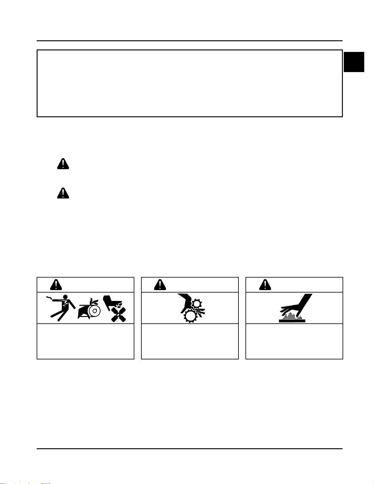
Carbon Monoxide can cause
severe nausea, fainting or death.
Do not operate engine in closed or
confined area.
WARNING
Electrical Shoc can cause injury.
Do not touch wires while engine is
running.
CAUTION
Lethal Exhaust Gases
Engine exhaust gases contain
poisonous carbon monoxide.
Carbon monoxide is odorless,
colorless, and can cause death if
inhaled. Avoid inhaling exhaust
fumes, and never run the engine
in a closed building or confined
area.
Explosive Gas
atteries produce explosive
hydrogen gas while being
charged. To prevent a fire or
explosion, charge batteries only in
well ventilated areas. Keep
sparks, open flames, and other
sources of ignition away from the
battery at all times. Keep batteries
out of the reach of children.
Remove all jewelry when servicing
batteries.
efore disconnecting the negative
(-) ground cable, make sure all
switches are OFF. If ON, a spark
will occur at the ground cable
terminal which could cause an
explosion if hydrogen gas or
gasoline vapors are present.
Electrical Shock
Never touch electrical wires or
components while the engine is
running. They can be sources of
electrical shock.
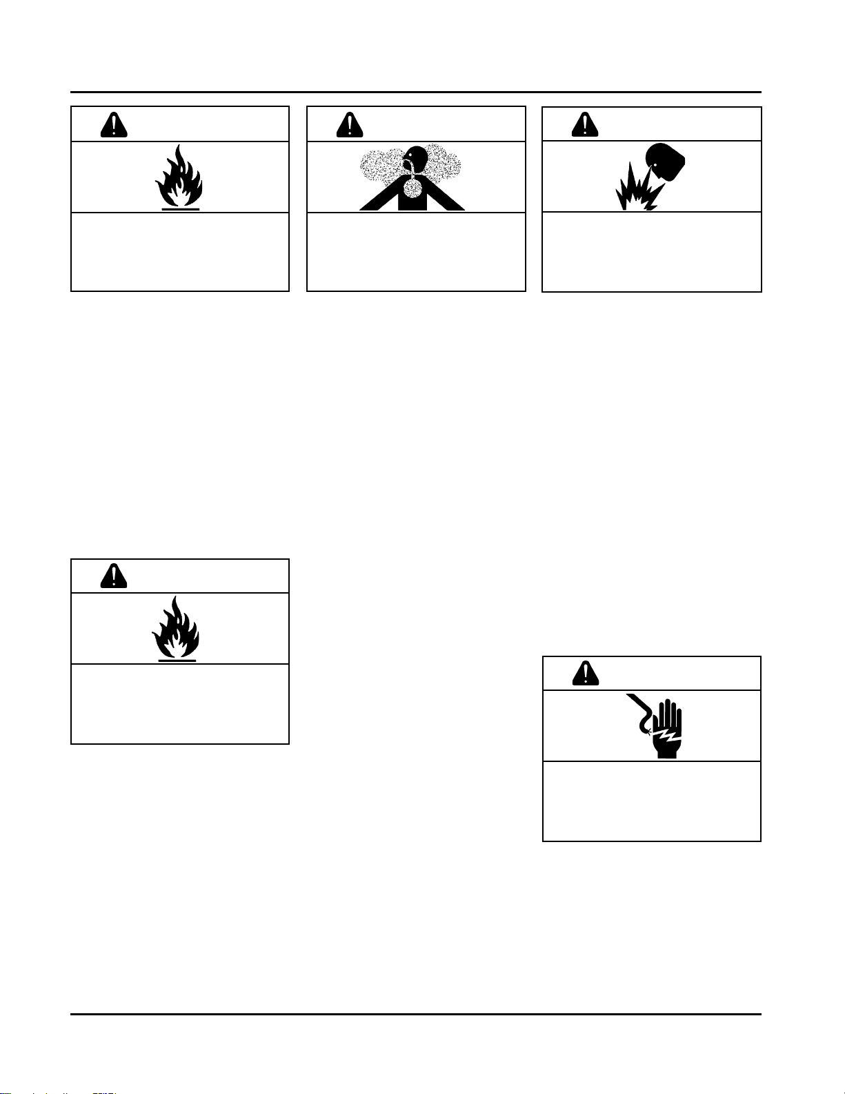
Explosive Fuel can cause fires and
severe burns.
Stop engine before filling fuel tank.
WARNING
Explosive Fuel
Gasoline is extremely flammable
and its vapors can explode if
ignited. Store gasoline only in
approved containers, in well
ventilated, unoccupied buildings,
away from sparks or flames. Do not
fill the fuel tank while the engine is
hot or running, since spilled fuel
could ignite if it comes in contact
with hot parts or sparks from
ignition. Do not start the engine
near spilled fuel. Never use
gasoline as a cleaning agent.
Cleaning Solvents can cause
severe injury or death.
Use only in well ventilated areas
away from ignition sources.
WARNING
Flammable Solvents
Carburetor cleaners and solvents
are extremely flammable. Keep
sparks, flames, and other sources
of ignition away from the area.
Follow the cleaner manufacturers
warnings and instructions on its
proper and safe use. Never use
gasoline as a cleaning agent.
WARNING
Explosive Gas can cause fires and
severe acid burns.
Charge battery only in a well
ventilated area. Keep sources of
ignition away.

1.3
Section 1
Safety and General Information
1
A. Model No.
Courage Vertical Shaft Engine
Numerical Designation
Version Code
S = Electric Start
First spec
written in this
model series
B. Spec. No.
Engine Model
Model
SV470
SV480
SV530
SV540
SV590
SV600
C. Serial No.
Year Manufactured Code
Code Year
32 2002
33 2003
34 2004
Factory Code
3205810334
Engine Identification Numbers
When ordering parts, or in any comm nication
involving an engine, always give the Model,
Specification, and Serial Numbers of the engine.
The engine identification n mbers appear on a decal
affixed to the engine shro ding. See Fig re 1-1. An
explanation of these n mbers is shown in Fig re 1-2.
Figure 1-2. Explanation of Engine Identification Numbers.
SV540-0001
Figure 1-1. Engine Identification Decal Location.
Identification Decal
MODEL NO.
SPEC. NO.
SERIAL NO.
REFER TO OWNER'S MANUAL FOR
SAFET , MAINTENANCE SPECS
AND ADJUSTMENTS. FOR SALES
AND SERVICE IN US/CANADA
CALL: 1-800-544-2444.
www.kohlerengines.com
KOHLER CO. KOHLER, WI USA
A
B
C
SV 540 S

1.4
Section 1
Safety and General Information
Oil Recommendations
Using the proper type and weight of oil in the
crankcase is extremely important, as is checking oil
daily and changing oil reg larly. Fail re to se the
correct oil or sing dirty oil ca ses premat re engine
wear and fail re.
Oil Type
Use high-q ality detergent oil of API (American
Petroleum Institute) service class SG, SH, SJ or
higher. Select the viscosity based on the air
temperat re at the time of operation as shown below.
NOTE: Using other than service class SG, SH, SJ or
higher oil or extending oil change intervals
longer than recommended can ca se engine
damage.
A logo or symbol on oil containers identifies the API
service class and SAE viscosity grade. See Fig re 1-3.
Fuel Recommendations
WARNING: Explosive Fuel
Gasoline is extremely flammable and its vapors can
explode if ignited. Store gasoline only in approved
containers, in well ventilated, unoccupied buildings,
away from sparks or flames. Do not fill the fuel tank
while the engine is hot or running, since spilled fuel
could ignite if it comes in contact with hot parts or
sparks from ignition. Do not start the engine near
spilled fuel. Never use gasoline as a cleaning agent.
General Recommendations
P rchase gasoline in small q antities and store in
clean, approved containers. A container with a capacity
of 2 gallons or less with a po ring spo t is
recommended. S ch a container is easier to handle
and helps eliminate spillage d ring ref eling.
Do not se gasoline left over from the previo s
season, to minimize g m deposits in yo r f el system
and to ens re easy starting.
Do not add oil to the gasoline.
Do not overfill the f el tank. Leave room for the f el to
expand.
Fuel Type
For best res lts, se only clean, fresh, nleaded
gasoline with a p mp sticker octane rating of 87 or
higher. In co ntries sing the Research method, it
sho ld be 90 octane minim m.
Unleaded gasoline is recommended, as it leaves less
comb stion chamber deposits. Leaded gasoline may
be sed in areas where nleaded is not available and
exha st emissions are not reg lated. Be aware
however, that the cylinder head will req ire more
freq ent service.
Gasoline/Alcohol blends
Gasohol ( p to 10% ethyl alcohol, 90% nleaded
gasoline by vol me) is approved as a f el for Kohler
engines. Other gasoline/alcohol blends are not
approved.
Gasoline/Ether blends
Methyl Tertiary B tyl Ether (MTBE) and nleaded
gasoline blends ( p to maxim m of 15% MTBE by
vol me) are approved as a f el for Kohler engines.
Other gasoline/ether blends are not approved.
Figure 1-3. Oil Container Logo.
Refer to Section 6 - L brication System for detailed
oil check, oil change, and oil filter change proced res.
*Use of synthetic oil having 5W-20 or 5W-30 rating is acceptable,
up to 4°C (40°F).
**Synthetic oils will provide better starting in extreme cold below
-23°C (-10°F).
***30 weight acceptable above 0°C (32°F).
***
** *

1.5
Section 1
Safety and General Information
1
Periodic Maintenance
WARNING: Accidental Starts
Disabling engine. Accidental starting can cause severe injury or death. efore working on the engine or
equipment, disable the engine as follows: 1) Disconnect the spark plug lead(s). 2) Disconnect negative (-)
battery cable from battery.
Maintenance Schedule
These req ired maintenance proced res sho ld be performed at the freq ency stated in the table. They sho ld
also be incl ded as part of any seasonal t ne- p.
Storage
If the engine will be o t of service for two months or
more, se the following storage proced re:
1. Clean the exterior s rfaces of the engine.
2. Change the oil and oil filter while the engine is still
warm from operation. See Change Oil and Oil
Filter in Section 6.
3. The f el system m st be completely emptied, or
the gasoline m st be treated with a stabilizer to
prevent deterioration. If yo choose to se a
stabilizer, follow the man fact rers
recommendations, and add the correct amo nt
for the capacity of the f el system. Fill the f el
tank with clean, fresh gasoline. R n the engine for
2-3 min tes to get stabilized f el into the
carb retor.
To empty the system, r n the engine ntil the tank
and system are empty.
4. D e to the deep recess aro nd the spark pl g,
blow o t the cavity with compressed air. Remove
the spark pl g. The spark pl g is most accessible
when the blower ho sing is removed for cleaning.
Add one tablespoon of engine oil into the spark
pl g hole. Install the pl g, b t do not connect the
pl g lead. Crank the engine two or three
revol tions. Connect the pl g lead.
5. Reinstall the blower ho sing, if removed
previo sly, and torq e the blower ho sing screws
to 7.5 N·m (65 in. lb.).
6. Store the engine in a clean, dry place.
¹Perform these maintenance procedures more frequently under extremely dusty, dirty conditions.
²Have a Kohler Engine Service Dealer perform this service.
Daily or Before
Starting Engine
Maintenance RequiredFrequency
Fill f el tank.
Check oil level.
Check air cleaner for dirty¹, loose, or damaged parts.
Check air intake and cooling areas, clean as necessary¹.
Every 2 Months
or 25 Hours
Service precleaner element¹ (if eq ipped).
Service air cleaner element¹ (if not eq ipped with precleaner).
Replace air cleaner element¹ (if eq ipped with precleaner).
Change oil and filter (refer to Viscosity Table, Page 1.4, based on seasonal
temperat res).
Remove blower ho sing and clean cooling areas.
Check that all fasteners are in place and components are properly sec red.
Replace f el filter.
Have bendix starter drive serviced².
Have valve lash checked/adj sted2.
Every 200 Hours
Annually or
Every 100 Hours
Every 500 Hours Replace spark pl g.
Check spark pl g condition and gap.
Every 2 Years or
200 Hours

1.6
Section 1
Safety and General Information
Figure 1-4. Typical Engine Dimensions.
Dimensions in millimeters. Inch equivalents shown in ().

1.7
Section 1
Safety and General Information
1
General Specifications¹
Power (@ 3600 RPM, corrected to SAE J1940)
SV470 ................................................................................................. 11.2 kW (15 HP)
SV480 ................................................................................................. 11.9 kW (16 HP)
SV530 ................................................................................................. 12.7 kW (17 HP)
SV540 ................................................................................................. 13.4 kW (18 HP)
SV590 ................................................................................................. 14.1 kW (19 HP)
SV600 ................................................................................................. 14.9 kW (20 HP)
Peak Torq e
SV470 @ 2600 RPM ............................................................................ 34.3 N·m (25.0 ft. lb.)
SV480 @ 2800 RPM ............................................................................ 34.6 N·m (25.5 ft. lb.)
SV530 @ 2600 RPM ............................................................................ 37.8 N·m (27.9 ft. lb.)
SV540 @ 2800 RPM ............................................................................ 39.1 N·m (29.0 ft. lb.)
SV590 @ 2600 RPM ............................................................................ 42.3 N·m (31.2 ft. lb.)
SV600 @ 2800 RPM ............................................................................ 44.2 N·m (32.0 ft. lb.)
Bore
SV470S, SV480S ................................................................................. 84 mm (3.30 in.)
SV530S, SV540S ................................................................................. 89 mm (3.50 in.)
SV590S, SV600S ................................................................................. 94 mm (3.70 in.)
Stroke ......................................................................................................... 86 mm (3.38 in.)
Displacement
SV470S, SV480S ................................................................................. 477 cc (29.1 c . in.)
SV530S, SV540S ................................................................................. 535 cc (32.6 c . in.)
SV590S, SV600S ................................................................................. 597 cc (36.4 c . in.)
Compression Ratio ...................................................................................... 8.5:1
Dry Weight .................................................................................................. 35.8 kg (79 lb.)
Oil Capacity (with filter) .............................................................................. 1.5 L (1.6 qt.)
Angle of Operation - Maxim m (at F ll Oil Level) All Directions.................... 25° Intermittent
Air Cleaner Base
Hex. N t Fastener Torq e ........................................................................... 5.5 N·m (48 in. lb.)
Mo nting Screw Fastener Torq e (Install Dry - DO NOT OIL) ....................... 8.0 N·m (70 in. lb.) Into new as-cast hole
5.5 N·m (48 in. lb.) Into sed hole
Blower Housing and Sheet Metal
M6 Fasteners Torq e .................................................................................. 7.5 N·m (65 in. lb.)
Cam Lever
Cam Lever Fastener Torq e ......................................................................... 7.5 N·m (65 in. lb.)
Cam Gears
End Play ..................................................................................................... 0.5/1.5 mm (0.019/0.059 in.)
R nning Side Clearance .............................................................................. 0.02/0.13 mm (0.001/0.005 in.)
1Val es are in Metric nits. Val es in parentheses are English eq ivalents. L bricate threads with engine oil prior to
assembly, EXCEPT for air cleaner base thread forming screw - install dry.

1.8
Section 1
Safety and General Information
Cam Gears (cont'd.)
Cam Gear-to-Cam Shaft R nning Assembly ............................................. 0.02/0.10 mm (0.001/0.004 in.)
Carburetor
F el Bowl Retaining Screw Torq e ........................................................... 5.1-6.2 N·m (45-55 in. lb.)
Closure Plate
Clos re Plate Fastener Torq e ................................................................ 24.5 N·m (216 in. lb.)
Balance Weight G ide Channel Width
New .................................................................................................. 17.95/18.05 mm (0.707/0.711 in.)
Max. Wear Limit ............................................................................... 18.13 mm (0.714 in.)
Connecting Rod
Cap Fastener Torq e (torq e in 2 increments) ......................................... 5.5, 11.5 N·m (50, 100 in. lb.)
Connecting Rod-to-Crankpin R nning Clearance
New ................................................................................................... 0.03/0.055 mm (0.0012/0.0022 in.)
Max. Wear Limit ................................................................................ 0.07 mm (0.0025 in.)
Connecting Rod-to-Crankpin Side Clearance ............................................ 0.25/0.59 mm (0.0098/0.0232 in.)
Connecting Rod-to-Piston Pin R nning Clearance .................................... 0.015/0.028 mm (0.0006/0.0011 in.)
Piston Pin End I.D.
New ................................................................................................... 22.015/22.023 mm (0.8667/0.8670 in.)
Max. Wear Limit ................................................................................ 22.036 mm (0.8675 in.)
Crankcase
Governor Cross Shaft Bore I.D.
New ................................................................................................... 6.025/6.05 mm (0.2372/0.2382 in.)
Max. Wear Limit ................................................................................ 6.063 mm (0.2387 in.)
Oil Drain Pl g Torq e ............................................................................... 14.0 N·m (125 in. lb.)
Crankshaft
End Play (free) ......................................................................................... 0.225/1.025 mm (0.0089/0.040 in.)
Crankshaft Bore in Crankcase I.D.
New .................................................................................................. 41.965/41.990 mm (1.6521/1.6531 in.)
Max. Wear Limit ............................................................................... 42.016 mm (1.654 in.)
Crankshaft Bore in Clos re Plate I.D
New .................................................................................................. 44.965/44.990 mm (1.7703/1.7713 in.)
Max. Wear Limit ............................................................................... 45.016 mm (1.7723 in.)
Flywheel End Main Bearing Jo rnal
O.D. New ....................................................................................... 44.913/44.935 mm (1.7682/1.7691 in.)
O.D. Max. Wear Limit .................................................................... 44.84 mm (1.765 in.)
Max. Taper ........................................................................................ 0.0220 mm (0.0009 in.)
Max. O t of Ro nd ............................................................................ 0.025 mm (0.001 in.)

1.9
Section 1
Safety and General Information
1
Crankshaft (cont'd.)
PTO End Main Bearing Jo rnal
O.D. New ....................................................................................... 41.913/41.935 mm (1.6501/1.6510 in.)
O.D. Max. Wear Limit .................................................................... 41.86 mm (1.648 in.)
Max. Taper ........................................................................................ 0.020 mm (0.0008 in.)
Max. O t of Ro nd ............................................................................ 0.025 mm (0.001 in.)
Crankshaft Bore in Clos re Plate R nning Clearance
New .................................................................................................. 0.03/0.077 mm (0.0012/0.003 in.)
Crankshaft Bore in Crankcase R nning Clearance
New .................................................................................................. 0.03/0.077 mm (0.0012/0.003 in.)
Connecting Rod Jo rnal O.D.
New .................................................................................................. 40.982/41.000 mm (1.6134/1.6141 in.)
Max. Wear Limit ............................................................................... 40.964 mm (1.612 in.)
Max. Taper ....................................................................................... 0.012 mm (0.0005 in.)
Max. O t of Ro nd ........................................................................... 0.025 mm (0.001 in.)
Crankshaft T.I.R.
PTO End, Crankshaft in Engine ....................................................... 0.15 mm (0.0059 in.)
Entire Crankshaft, in V-Blocks .......................................................... 0.10 mm (0.0039 in.)
Crankshaft Eccentrics O.D.
New .................................................................................................. 66.940/66.970 mm (2.6354/2.6366 in.)
Max. Wear Limit ............................................................................... 66.89 mm (2.633 in.)
Balance Weight Bearing S rface I.D.
New .................................................................................................. 67.011/67.086 mm (2.6382/2.6412 in.)
Max. Wear Limit ............................................................................... 67.140 mm (2.6430 in.)
Balance Weight Screw Torq e ................................................................ 10.0 N·m (90 in. lb.)
G ide Pin O.D.
New .................................................................................................. 11.950/11.975 mm (0.4705/0.4715 in.)
Max. Wear Limit ............................................................................... 11.900 mm (0.4685 in.)
G ide Shoe Width
New .................................................................................................. 17.85/17.90 mm (0.703/0.705)
Max. Wear Limit ............................................................................... 17.75 mm (0.6988 in.)
G ide Shoe Hole I.D.
New .................................................................................................. 12.000/12.025 mm (0.4724/0.4734 in.)
Max. Wear Limit ............................................................................... 12.050 mm (0.4744 in.)
Cylinder Bore
Cylinder Bore I.D.
New
SV470, SV480 ................................................................................ 84.000/84.025 mm (3.307/3.308 in.)
SV530, SV540 ................................................................................ 89.000/89.025 mm (3.504/3.505 in.)
SV590, SV600 ................................................................................ 94.010/94.035 mm (3.701/3.702 in.)
Max. Wear Limit
SV470, SV480 ................................................................................ 84.073 mm (3.310 in.)
SV530, SV540 ................................................................................ 89.073 mm (3.507 in.)
SV590, SV600 ................................................................................ 94.073 mm (3.704 in.)

1.10
Section 1
Safety and General Information
Cylinder Bore I.D. (cont'd.)
Max. Taper ....................................................................................... 0.05 mm (0.002 in.)
Max. O t of Ro nd ........................................................................... 0.12 mm (0.0047 in.)
Cylinder Head
Cylinder Head Fastener Torq e (torq e in 2 increments) .......................... 20.5, 41.0 N·m (180, 360 in. lb.)
Max. O t-of-Flatness .............................................................................. 0.8 mm (0.003 in.)
Rocker Arm Pivot St d Torq e ................................................................ 13.5 N·m (120 in. lb.)
Rocker Arm Adj stment N t Set Screw .................................................. 5.5 N·m (50 in. lb.)
Electric Starter
Thr Bolt Torq e ..................................................................................... 3.3-3.9 N·m (30-35 in. lb.)
Mo nting N t Torq e .............................................................................. 3.6 N·m (32 in. lb.)
N t (Top) Positive (+) Br sh Lead Terminal ............................................ 1.6-2.8 N·m (15-25 in. lb.)
N t (Flange) Positive (+) Br sh Lead Terminal ....................................... 2.2-4.5 N·m (20-40 in. lb.)
Fan/Flywheel
Flywheel Retaining Screw Torq e ........................................................... 66.5 N·m (588 in. lb.)
Governor
Governor Cross Shaft-to-Crankcase R nning Clearance ....................... 0.013/0.075 mm (0.0005/0.003 in.)
Governor Cross Shaft O.D.
New .................................................................................................. 5.975/6.012 mm (0.2352/0.2367 in.)
Max. Wear Limit ............................................................................... 5.962 mm (0.2347 in.)
Governor Gear Shaft-to-Governor Gear R nning Clearance .................. 0.09/0.16 mm (0.0035/0.0063 in.)
Governor Gear Shaft O.D.
New .................................................................................................. 5.99/6.00 mm (0.2358/0.2362 in.)
Max. Wear Limit ............................................................................... 5.977 mm (0.02353 in.)
Ignition
Spark Pl g Type (Champion® or Eq ivalent) ............................................. RC12YC or QC12YC
Spark Pl g Gap ...................................................................................... 0.76 mm (0.030 in.)
Spark Pl g Torq e .................................................................................. 24-30 N·m (18-22 ft. lb.)
Ignition Mod le Air Gap .......................................................................... 0.203/0.305 mm (0.008/0.012 in.)
Ignition Mod le Fastener Torq e .............................................................. 6.0 N·m (55 in. lb.) Into new as-cast hole
4.0 N·m (35 in. lb.) Into sed hole
Muffler
M ffler Retaining N ts Torq e ................................................................ 24.4 N·m (216 in. lb.)
Oil Filter
Oil Filter Torq e ...................................................................................... 10-13 N·m (90-110 in. lb.)

1.11
Section 1
Safety and General Information
1
Oil Filter Pad Pipe Plug
1/8 N.P.T.F. Torq e ................................................................................. 4.5-5.0 N·m (40-46 in. lb.)
Oil Pump
Mo nting Screw Torq e .......................................................................... 4.0 N·m (35 in. lb.)
P mp Gears-to-Crankcase Side Clearance............................................ 0.165/0.315 mm (0.0065/0.0124 in.)
Oil Sentry
Press re Switch Torq e .......................................................................... 4.5-5.0 N·m (40-45 in. lb.)
Piston, Piston Rings, and Piston Pin
Piston Pin Bore I.D.
New .................................................................................................. 22.006/22.012 mm (0.8685/0.8666 in.)
Max. Wear Limit ............................................................................... 22.025 mm (0.8671 in.)
Piston Pin O.D.
New .................................................................................................. 21.995/22.0 mm (0.8659/0.8661 in.)
Max. Wear Limit ............................................................................... 21.994 mm (0.8658 in.)
Top Compression Ring-to-Groove Side Clearance ................................. 0.04 mm (0.0016 in.)
Middle Compression Ring-to-Groove Side Clearance ............................ 0.04 mm (0.0016 in.)
Top and Middle Compression Ring End Gap
New Bore
Top Ring ......................................................................................... 0.15/0.40 mm (0.006/0.016 in.)
Middle Ring .................................................................................... 0.30/0.55 mm (0.012/0.022 in.)
Used Bore (max.) ............................................................................. 0.77 mm (0.030 in.)
Piston Thr st Face O.D.²
SV470, SV480
New ................................................................................................ 83.948/83.962 mm (3.3050/3.3056 in.)
Max. Wear Limit ............................................................................. 83.828 mm (3.3003 in.)
SV530, SV540
New ................................................................................................ 88.948/88.962 mm (3.5018/3.5024 in.)
Max. Wear Limit ............................................................................. 88.828 mm (3.4972 in.)
SV590, SV600
New ................................................................................................ 93.928/93.942 mm (3.6980/3.6985 in.)
Max. Wear Limit ............................................................................. 93.828 mm (3.6940 in.)
Piston Thr st Face-to-Cylinder Bore² R nning Clearance
SV470, SV480, SV530, SV540 ........................................................ 0.0575 mm (0.0023 in.)
SV590, SV560 .................................................................................. 0.0875 mm (0.0034 in.)
Rectifier-Regulator
Mo nting Screw Torq e ........................................................................... 6.0 N·m (55 in. lb.) Into new as cast hole
4.0 N·m (35 in. lb.) Into sed hole
Speed Control
Speed Control Bracket Assembly Fastener Torq e ................................. 11.0 N·m (95 in. lb.) Into new as-cast hole
7.5 N·m (65 in. lb.) Into sed hole
²Meas re 8 mm (0.314 in.) above the bottom of the piston skirt at right angles to the piston pin.

1.12
Section 1
Safety and General Information
Stator
Stator Mo nting Screw Torq e ................................................................. 6.0 N·m (55 in. lb.) Into new as-cast hole
4.0 N·m (35 in. lb.) Into sed hole
Throttle/Choke Controls
Governor Control Lever Fastener Torq e .................................................. 7.0-8.5 N·m (60-75 in. lb.)
Valve Cover
Valve Cover Fastener Torq e ................................................................... 11.0 N·m (95 in. lb.) Into new as-cast hole
7.5 N·m (65 in. lb.) Into sed hole
Valves and Valve Lifters
Valve Lash³ ............................................................................................. 0.076 mm (0.003 in.)
Intake Valve Minim m Lift ........................................................................ 8.9 mm (0.350 in.)
Exha st Valve Minim m Lift .................................................................... 8.9 mm (0.350 in.)
Nominal Valve Seat Angle ....................................................................... 45°
Intake Valve Stem-to-Valve G ide R nning Clearance .............................. 0.038/0.076 mm (0.0015/0.003 in.)
Exha st Valve Stem-to-Valve G ide R nning Clearance .......................... 0.050/0.88 mm (0.0020/0.0035 in.)
Intake Valve G ide I.D.
New .................................................................................................. 6.038/6.058 mm (0.2377/0.2385 in.)
Max. Wear Limit ............................................................................... 6.135 mm (0.2415 in.)
Intake Valve Stem Diameter
New .................................................................................................. 5.982/6.0 mm (0.2355/0.2362 in.)
Exha st Valve G ide I.D.
New .................................................................................................. 6.038/6.058 mm (0.2377/0.2385 in.)
Max. Wear Limit ............................................................................... 6.160 mm (0.2425 in.)
Exha st Valve Stem Diameter
New .................................................................................................. 5.970/5.988 mm (0.235/0.2357 in.)
³Check valve lash every 200 ho rs, adj st as req ired.

1.13
Section 1
Safety and General Information
1
General Torque Values
Metric Fastener Torque Recommendations for Standard Applications
Size
M4 1.2 (11) 1.7 (15) 2.9 (26) 4.1 (36) 5.0 (44) 2.0 (18)
M5 2.5 (22) 3.2 (28) 5.8 (51) 8.1 (72) 9.7 (86) 4.0 (35)
M6 4.3 (38) 5.7 (50) 9.9 (88) 14.0 (124) 16.5 (146) 6.8 (60)
M8 10.5 (93) 13.6 (120) 24.4 (216) 33.9 (300) 40.7 (360) 17.0 (150)
Tightening Torque: N·m (ft. lb.) + or - 10%
Property Class
M10 21.7 (16) 27.1 (20) 47.5 (35) 66.4 (49) 81.4 (60) 33.9 (25)
M12 36.6 (27) 47.5 (35) 82.7 (61) 116.6 (86) 139.7 (103) 61.0 (45)
M14 58.3 (43) 76.4 (55) 131.5 (97) 184.4 (136) 219.7 (162) 94.9 (70)
Noncritical
Fasteners
Into Aluminum
Noncritical
Fasteners
Into Aluminum
Tightening Torque: N·m (in. lb.) + or - 10%
Property Class
4.8 5.8 8.8 10.9 12.9
4.8 5.8 8.8 10.9 12.9
N·m = in. lb. x 0.113
N·m = ft. lb. x 1.356
in. lb. = N·m x 8.85
ft. lb. = N·m x 0.737
Torque
Conversions
Oil Drain Plugs Tightening Torque: Nm (English Equiv.)
Size
1/8" NPT
1/4"
3/8"
1/2"
3/4"
X-708-1
Into Cast Iron
17.0 (150 in. lb.)
20.3 (180 in. lb.)
27.1 (20 ft. lb.)
33.9 (25 ft. lb.)
27.1/33.9 (20/25 ft. lb.)
Into Aluminum
4.5 (40 in. lb.)
11.3 (100 in. lb.)
13.6 (120 in. lb.)
17.6 (13 ft. lb.)
21.7 (16 ft. lb.)
27.1/33.9 (20/25 ft. lb.)

1.14
Section 1
Safety and General Information

2.1
Section 2
Special Tools
2
Section 2
Special Tools
SV470-600
Some special tools for this engine are:
Flywheel P ller Kit ........................................................................................... NU3226
Valve G ide Reamer ......................................................................................... KO1026
Rocker Arm Spanner Wrench ........................................................................... (obtain locally)
Water Manometer ............................................................................................ KO1048
Vac m Ga ge ................................................................................................ KO3223
Cylinder Leakdown Tester ................................................................................. KO3219
Ignition System Tester ...................................................................................... KO1046
Amp Meter ....................................................................................................... KO3218
Ind ctance Tachometer .................................................................................... KO3216
Figure 2-1. Tool Catalog and Price List.
Certain q ality tools are designed to help yo perform specific disassembly, repair, and reassembly proced res.
By sing tools designed for the job, yo can service engines easier, faster, and safer! In addition, yo ll increase
yo r service capabilities and c stomer satisfaction by decreasing engine downtime.
Kohler special tools are handled by SPX Corp., a division of Owatonna Tool Corp. (OTC). The tools are easy to
p rchase by contacting SPX/OTC by phone, fax, or mail.
Phone: 1-800-533-0492
International: 1-507-455-7223
8:00 am 8:00 pm EST
Fax: 1-800-578-7375
1-586-578-7375
International: 1-507-455-7063
Mail: SPX Corp., OTC
28635 Mo nd Rd.
Warren, MI 48092-3499
Some of the specialty tools are shown and mentioned at vario s points in this man al. A complete catalog of all
available tools may be ordered nder Kohler Part No. TP-2546. The tool price list is available nder Kohler Part No.
TP-2547.
Special Tools You Can Ma e
Flywheel Holding Tool
Flywheel removal and reinstallation becomes a snap
sing a handy holding tool yo can make o t of a piece
of an old j nk flywheel ring gear as shown in Fig re
2-2. Using an abrasive c t-off saw, c t o t a six tooth
segment of the ring gear as shown. Grind off any b rrs
or sharp edges. The segment can be sed in place of a
strap wrench. Invert the segment and place it between
the ignition mod le bosses on the crankcase, so the
tool teeth engage the ring gear teeth on the flywheel.
The bosses will lock the tool and flywheel in position
for loosening, tightening or removing with a p ller.

2.2
Section 2
Special Tools
Figure 2-2. Flywheel Holding Tool.
Rocker Arm/Crankshaft Tool
If yo dont have a spanner wrench to lift the rocker
arms or to t rn the crankshaft, yo can make a tool for
doing this o t of an old j nk connecting rod.
Find a sed connecting rod from a 10 HP or larger
engine. Remove and discard the rod cap. If it is a Posi-
Lock rod, yo will also need to remove the st ds. If it is
a Command rod, yo will need to grind off the aligning
steps, so the joint s rface is flat. Find a 1" long
capscrew with the correct thread size to match the
threads in the connecting rod. Obtain a flat washer
with the correct I.D. to slip on the capscrew and an
O.D. of approximately 1". Kohler Part No. 12 468 05-S
can be sed if yo dont have the right size on hand.
Assemble the capscrew and washer to the joint
s rface of the rod, as shown in Fig re 2-3.
Figure 2-3. Rocker Arm/Crankshaft Tool.

3.1
Section 3
Trou leshooting
3
Section 3
Troubleshooting
SV470-600
Troubleshooting Guide
When tro bles occ r, be s re to check the simple
ca ses which, at first, may seem too obvio s to be
considered. For example, a starting problem co ld be
ca sed by an empty f el tank.
Some common types of engine tro bles are listed
below. Use these to help locate the possible ca se(s).
Engine Cranks But Will Not Start
1. Empty f el tank.
2. F el sh t-off valve closed.
3. Dirt or water in the f el system.
4. Clogged f el line.
5. Spark pl g lead disconnected.
6. Key switch or kill switch in off position.
7. Fa lty spark pl g.
8. Fa lty ignition mod le.
9. Inoperative f el solenoid.
10. Choke not closing.
Engine Starts But Does Not Keep Running
1. Vent in f el cap restricted.
2. Dirt or water in the f el system.
3. Fa lty choke or throttle controls.
4. Loose wires or connections that short the kill
terminal of ignition mod le to gro nd.
5. Fa lty carb retor.
6. Fa lty cylinder head gasket.
Engine Starts Hard
1. PTO drive is engaged.
2. Dirt or water in the f el system.
3. Clogged f el line.
4. Loose or fa lty wires or connections.
5. Fa lty choke or throttle controls.
6. Fa lty spark pl g.
7. Low compression.
8. Fa lty ACR mechanism.
Engine Will Not Crank
1. PTO drive is engaged.
2. Battery is discharged.
3. Safety interlock switch is engaged.
4. Loose or fa lty wires or connections.
5. Fa lty key switch or ignition switch.
6. Fa lty electric starter.
7. Seized internal engine components.
Engine Runs But Misses
1. Dirt or water in the f el system.
2. Spark pl g fa lty or fo led.
3. Spark pl g lead boot loose on pl g.
4. Loose wires or connections that intermittently
short the kill terminal of ignition mod le to gro nd.
5. Engine overheated.
6. Fa lty ignition mod le or improperly gapped.
Engine Will Not Idle
1. Vent in f el cap restricted.
2. Dirt or water in the f el system.
3. Fa lty spark pl g.
4. Idle f el adj sting needle improperly set.
5. Idle speed adj sting screw improperly set.
6. Low compression.
7. Stale f el and/or g m in carb retor.
Engine Overheats
1. Air intake/grass screen, cooling fins, or cooling
shro ds clogged.
2. Excessive engine load.
3. Low crankcase oil level.
4. High crankcase oil level.
5. Fa lty carb retor.
Engine Knocks
1. Excessive engine load.
2. Low crankcase oil level.
3. Old/improper f el.
4. Internal wear or damage.
This manual suits for next models
5
Table of contents
Other Husqvarna Engine manuals

Husqvarna
Husqvarna HH 163MP User manual

Husqvarna
Husqvarna HV 703 User manual

Husqvarna
Husqvarna 3122 k User manual

Husqvarna
Husqvarna T 250 Instruction manual

Husqvarna
Husqvarna HS 139A Instruction manual

Husqvarna
Husqvarna DMS 160 A User manual

Husqvarna
Husqvarna Tuff Torq K61 User manual

Husqvarna
Husqvarna HH 389MPC User manual