manuals.online logo
Brands
  1. Home
  2. •
  3. Brands
  4. •
  5. O.S. engine
  6. •
  7. Engine
  8. •
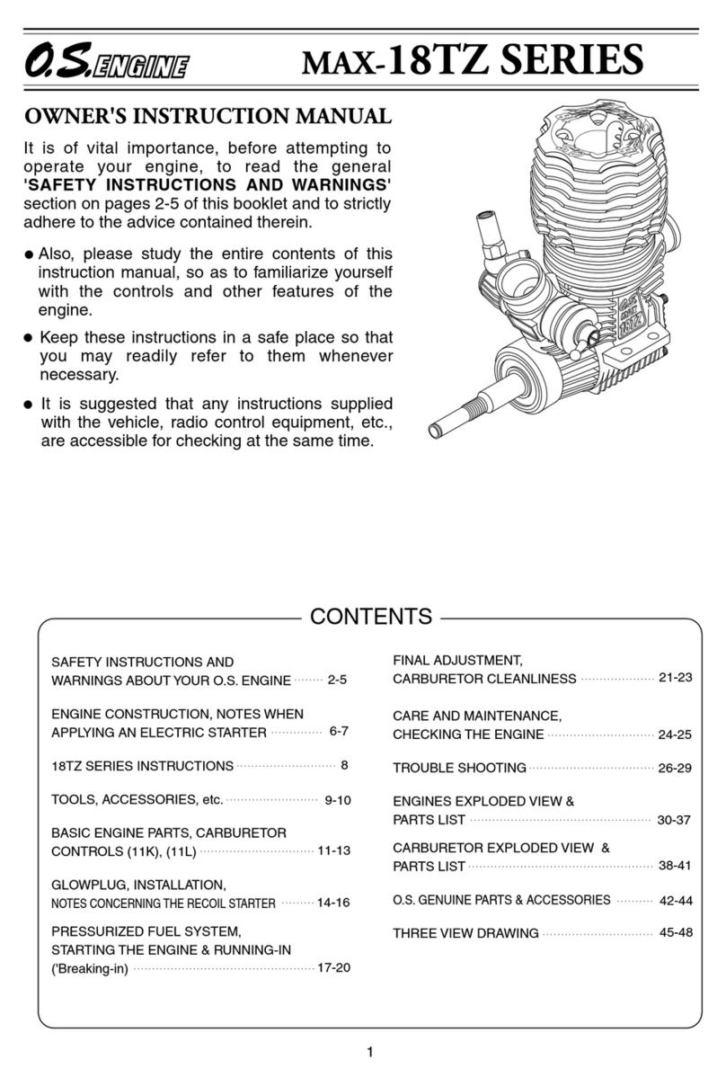
  9. O.S. engine OCA-3100HV User manual

O.S. engine OCA-3100HV User manual

- 4 - - 1 -

●
50/70
OCA-3070HV
OMA-5015-650
OMA-5020-490
C Copyright 2021 by O.S.Engines Mfg. Co., Ltd. All rights reserved. 102100
OCA-3100HV
OCA-3070HV
70/F3A
OMA-5020-490
OMA-5025-375
OMA-6030-220
OMA-4043-165
OMA-4043-172
OMA-5025-375
OCA-3100HV
OCA-3070HV
High-Resolution
OPTO
55V
12S
OCA-3100HV
High-Resolution
OPTO
55V
12S
Pay careful attention to the advices with the following headings.
DANGER
This covers the possibility which
might involve death and serous
injury.
These cover the possibilities
which might involve death and
serious injury and also may cause
damage or injury.
WARNINGS NOTES
These cover the many other
possibilities, generally less obvious
source of danger, but which, under
certain circumstances, may also
cause danger or injury.
Graphic symbols: Prohibited items Items never fail to take action
TEL. (06) 6702-0225
FAX. (06) 6704-2722
6-15 3-Chome Imagawa Higashisumiyoshi-ku
Osaka 546-0003, Japan
IMPORTANT: It is of vital importance, before attempting to
operate your ESC to read through this instruction manual.
INSTRUCTIONS
ESC for airplane brushless motors
Before using OCA-3100HV/OCA-3070HV
Misuse or abuse of LiPo batteries is very danger-
ous.
Be sure to follow the instruction manual supplied
with the batteries.
Notes on installation
WARNINGS
Never use the ESC beyond the working conditions listed in the
specifications listing.
Do not mistake the polarity of the batteries.
Reverse connection may cause fire and ESC will be damaged or be burnt
instantly.
Never short out any place of the ESC, batteries, motor,
receiver and connectors.
Short circuit may cause fire and ESC will be damaged or be burnt instantly.
Be sure to install the ESC so that the soldering connection of the
input/output wires may not touch conductive part.
Be sure to install the receiver and receiver antenna away from
the place where high current flows such as ESC, motor wires,
battery wires, power batteries.
Malfunction of the receiver due to noise will cause to lose model control
which is very dangerous.
Be sure to insert connectors all the way securely.
Disconnection due to vibration may cause to lose model control which is
very dangerous.
Be sure to install the ESC so that oil, grease and water may
not come in contact with the ESC.
Be sure to install the ESC at the place where there is plenty of
air flow for cooling.
Do not wrap the ESC with aluminum foil, etc.
Wrapping may spoil cooling effect and the ESC may not develop its original
performance.
Be sure to install the motor securely and fix all the wires.
NOTE
Do not disassemble. Do not open the ESC case.
Opening of the case may cause damage inside components and render it
irreparable.
Notes on operation
WARNINGS
Never touch or allow any part of the body to come into contact
with any rotating part while operating.
Sudden rotating may cause serious
Be careful with some receivers the motor may rotate for a moment when
the power puts on.
Do not fly when rainy.
Entry of water drops into the ESC may cause malfunction and out of model
control which is very dangerous. Also, it will cause failure. If malfunction is
detected due to entry of water drops, send the ESC to the manufacturer or
its distributor in each country for inspection and repair.
Be sure to follow the procedures mentioned below as to ON
and OFF of the power switch.
ON: Hold the throttle stick at stop position. Switch on the transmitter then
receiver power.
OFF: Hold the throttle stick at stop position. Switch off the receiver then
transmitter power.
With reverse procedure propeller may rotate suddenly, which is very
dangerous.
Be sure to remove the batteries when not in use.
Accidental switching on may cause sudden rotating of propeller or cause
fire, which is very dangerous.
Be sure to check the ESC and all the movements of model
controls before attempting flight.
Incorrect settings or using of unsuitable model may cause to lose model
control which is very dangerous.
NOTE
Do not touch the motor nor ESC right after flight.
Touching them may cause burn.
OCA-3100HV/OCA-3070HV are ESCs for airplane
brushless motors.
For optimum performance of the ESCs, we
recommend you to choose OS brand brushless
motors.
Motors other than OS brand may not work
properly with the ESC.
Use the ESC with combination of OS motors
listed in this manual.
Solder suitable connectors to the lead wires of
the ESC to connect a battery.
Do not connect the connectors without
soldering to a battery.
Active Freewheel (regenerative braking system)
Setting choice : OFF / ON
Default setting : OFF
Setting range : OFF / 40~120%
Select ON or OFF with the LEFT and the RIGHT buttons.
The “Brake Mode” activates when the throttle stick is moved up to
30% or more.
Current limit
Set the value with the LEFT and the RIGHT buttons.
This parameter regulates excessive current for energy saving and
reducing heat emission.
Default setting : 100%
Setting range : OFF / ON
Default setting : OFF
Governor settings
Select ON or OFF with the LEFT and the RIGHT buttons.
When you use the governor, select ON and decide the values of
the following items to set the governor gain.
Motor Type
Setting choice : Standard value / OMA-4013/OMA-6030/
OMH-4535
Select the value with the LEFT and the RIGHT buttons.
Select Standard value usually.
Throttle Mode
Setting choice : Automatic / set value
Set the value with the LEFT and the RIGHT buttons.
Select the setting item with the UP and the DOWN buttons.
When you do not choose “Automatic” and set the value:
PWM value for throttle stop position: 800~1200
PWM value for maximum throttle position: 1800~2200
Restore Default
Setting choice : NO / YES
Default setting : NO
Select NO or YES with the LEFT and the RIGHT buttons.
In case you select YES, press the RIGHT button again to confirm
to restore Default settings.
Select the setting item with the UP and the DOWN buttons.
Class Motor ESC
Specifications, design, and contents of the instruction manual
of the motorare subject to change without prior notice for
improvement.
Please contact[email protected] or professional@os-en
gines.co.jp for questions and inquiries.
Minimum rotation position setting: Min Speed 1~25
Maximum rotation position setting: Max Speed 1~25
Minimum rotation position setting is the rpm when a throttle stick
is at full low position.
Maximum rotation position setting is the highest rpm setting.
Setting range : 10%~40%
Default setting : 20%
Governor Gain setting
Set the value with the LEFT and the RIGHT buttons.
The larger the value is set, the more the motor rpm increases.
Start from 20% then find your best setting.
Setting range : 1~25
Default setting : 1
Min Speed setting
Set the value with the LEFT and the RIGHT buttons to decide
the timing when the governor starts to work.
The governor starts to work the earliest at 1. At 25 it starts the
latest.
The value is usually set 1 unless you want to change it.
Setting range : 1~25
Default setting : 8
Max Speed setting
Set the value with the LEFT and the RIGHT buttons.
This is to set the speed to reach the maximum rpm according to
the throttle move.
The rpm rises linearly at 8 to the maximum rpm, but it depends
on how the throttle curve is set. Reduce the value in case the
rpm reaches the maximum rpm before full throttle.
Increase the value in case the rpm does not reach the
maximum rpm even full throttle.
[Recommended Motor/ESC classified by airplane class.]
Electric current depends on combination of battery cells and size
of propeller.
Read instructions of O.S. motors carefully before use not to apply
excessive electric current more than its capacity to the ESC.
Note:
The governor system of this ESC does not
conform to FAI F3A regulations.
Disable the function when you participate in the
competitions based on FIA F3A regulations.
(Disable the function for FAI F3A competitions.)
- 2 - - 3 -


50~400Hz
14.8V-52.2V(4S LiPo-12S LiHV)
150A (5 seconds, 20℃, cooling air 5m/s)
100A (180 seconds, 20℃, cooling air 5m/s)
None
(Input signals are insulated by a photocoupler.)
Fixed 0~25
°
adjustable by 1
°
Selectable : 8kHz, 16kHz, 32kHz
ON/OFF
OFF or adjustable 0~100% by 2%
Adjustable 0~2.0 sec. by 0.1 sec.
OFF or adjustable 40~120% by 5%
ON/OFF
Automatic/Set value, Stop Position/Maximum Throttle Position
37mm(W) x 95mm(L) x 16mm(H)
125g including lead wires and 4φ connectors
13AWG, 100mm length, covered by silicone tube
14AWG, 100mm length, covered by silicone tube
22AWG, 3-Wire (Black-red-white) 240±10mm
22AWG, 3-Wire (Brown-red-orange) 140±10mm
The parameters can be set with OCP-3 ESC programmer
Start protection/Low voltage cutoff/Non signal cutoff/
Overheat protection/Anti-spark protection/
Automatic battery cell quantity recognizing system
OCA-3100HV OCA-3070HV
OCA-3100HV/OCA-3070HV
OCA-3100HV
High-Resolution
OPTO
55V
12S
to be connected to a brushless
motor
[OCA-3100HV / OCA-3070HV SPECIFICATIONS]
Input signal period
Voltage Range
Maximum peak current
Maximum current
Intemal BEC
Advance Timing
PWM Frequency
Active Freewheel
Braking force setting
Brake speed setting
Current limit
Governor
Throttle mode
Outside dimension
Weight
Batterie Leads
Motor Leads
Input signal leads
Setting leads
Setting
Protective function
Edit buttons
Connecting the programmer
Operation of the edit buttons
Setting items
Battery type
Battery Cut-off
Cut-off type
Motor timing
Acceleration
Drive Frequency
Reverse Rotation
Brake Force
How to set the ESC using OCP-3
Battery type
Setting choice : LiPo or NiCd
Default setting : LiPo
Battery Cut-off
Setting range : 2.9V~3.2V
Default setting : 3.2V
Cut-off type
Setting choice : Reduce power by 50% or
Switch OFF (stop the motor)
Default setting : Reduce power by 50%
Setting range : 0~25°
Motor Timing
Default setting : 12°
Acceleration
Setting range : 20~200
Default Setting : 100
Start Power
[preparation] Solder suitable connectors to lead wires (red, black) of the ESC. Use a piece of shrink tube for insulation at each connecting
point. Solder suitable female connectors to the three lead wires of the ESC, which are to be connected to three male connectors of the
brushless motor. Use shrink tubes for insulation at connecting points.
How to connect OCA-3100HV/OCA-3070HVHow to connect OCA-3100HV/OCA-3070HV
The drawing below shows connection of OCA-3100HV/OCA-3070HV.
Positive side
(+, red)
Connect each wire to a
batteries; positive to positive,
negative to negative.
Do not make the polarity
reversed.
Negative side
(-, black)
Brown-red-orange wire
Black-red-white wire
to be connected to change the
program using OCP-3
to be connected to a throttle
channel of a transmitter
A receiver battery should be used
independently to connect to a receiver.
Solder suitable female connectors to the
three lead wires. Use a piece of shrink tube
for insulation to each connecting point.
Start protection: the device stops the motor when it is started unintentionally.
the device stops the motor when it loses control, or before
incoming voltage.
Low voltage cut-off:
the device cut off the ESC when no signal from the transmitter is
detected.
No signal cut-off:
the device regulate the output to protect FETs when
temperature of ESC rapidly rises due to overload.
Protection against overheating:
the device reduces sparks when the ESC is connected to a battery.
Anti-spark:
the device detects number of battery cells
automatically.
Automatic detection of battery cells:
In order to maintain an optimum current and rated current of the ESC, cooling air;
propeller slip stream and natural air of atmospheric temperature 20℃ or lower at
wind speed (5m/s or more) over the entire heat sink is required.
The maximum performance limit of ESC greatly changes depending on environmen-
tal factors such as atmospheric temperature and humidity.
Battery voltage is detecting system. A buzzer tells you how many cells in a battery.
The active free-wheeling reduces heat of the ESC generated during operation, which
is a waste.
Settings of the ESC using an
ESC programmer of OCP-3
Settings of the ESC using an
ESC programmer of OCP-3
With OCP-3 (optional), you can set the ESC more quickly and
easily.
Connect OCA-3100HV/OCA-3070HV to the ESC socket of
OCP-3, and a battery (4.8〜7.4V) to the BATT socket of
OCP-3.
Select a setting item by pressing the UP or the DOWN
button.
The LEFT and the RIGHT buttons are to select each item in
the setting or to change the setting.
The following items can be set with OCP-3.
Setting items (model type: airplane)
Brake Speed
Start Power
Active Freewheel
Current Limit
Governor settings
Motor Type
Throttle Mode
Restore Default
Disconnect the battery from the ESC.
Connect a battery (4.8〜7.4V) to the socket BATT socket of
OCP-3.
Select a setting item by pressing the UP and the DOWN buttons.
Select or change the setting item by pressing the LEFT and the
RIGHT buttons.
Any chosen value of setting is memorized in the ESC automati-
cally one by one without requesting you any further action to
memorize the value in the ESC.
Select the battery type and number of cells with the LEFT and
the RIGHT buttons.
Setting a number of the battery cells: AUTO
In case NiCd is selected, pass the setting item .
The cut-off voltage is automatically fixed at 50% of an initial value.
Set the cut-off voltage when you select LiPo battery with the
LEFT and the RIGHT button.
Select how to cut off the power when voltage of the battery drops
to the set value of cut-off voltage with the LEFT and the RIGHT
buttons.
For 2~4-pole motors, usually we recommend 0~5°
Set the value within the range shown below.
for inner rotor type : 0~10° for outer rotor type : 10~25°
Select the advance timing with the LEFT and the RIGHT buttons.
This is the speed at which the ESC reaches the top speed.
Select the acceleration value with the LEFT and the RIGHT
buttons.
The setting value is 50 or lower in case a motor is turned
ON/OFF by an on-board switch of a transmitter such as gliders.
Drive Frequency
Setting choice : 8kHz / 16kHz / 32kHz
Select the value with the LEFT and the RIGHT buttons.
We recommend 32kHz for 10-pole or less motors.
Reverse Rotation
Setting choice : Normal / Reverse
Select the direction of rotation with the LEFT and the RIGHT buttons.
Brake Force
Setting range : OFF~100%
Default Setting : OFF
Set the value with the LEFT and the RIGHT buttons.
Brake Speed
Setting range : 0~2.0 seconds
Default Setting : 0.1 second
Set the value with the LEFT and the RIGHT buttons.
Setting choice : Super Soft / Very Soft / Soft / Hard
Default Setting : Soft
Select the start power with the LEFT and the RIGHT buttons.
50~400Hz
14.8V-52.2V(4S LiPo-12S LiHV)
90A (5 seconds, 20℃, cooling air 5m/s)
70A (180 seconds, 20℃, cooling air 5m/s)
None
(Input signals are insulated by a photocoupler.)
Fixed 0~25
°
adjustable by 1
°
Selectable : 8kHz, 16kHz, 32kHz
ON/OFF
OFF or adjustable 0~100% by 2%
Adjustable 0~2.0 sec. by 0.1 sec.
OFF or adjustable 40~120% by 5%
ON/OFF
Automatic/Set value, Stop Position/Maximum Throttle Position
37mm(W) x 95mm(L) x 16mm(H)
124g including lead wires and 4φ connectors
13AWG, 100mm length, covered by silicone tube
14AWG, 100mm length, covered by silicone tube
22AWG, 3-Wire (Black-red-white) 240±10mm
22AWG, 3-Wire (Brown-red-orange) 140±10mm
The parameters can be set with OCP-3 ESC programmer
Start protection/Low voltage cutoff/Non signal cutoff/
Overheat protection/Anti-spark protection/
Automatic battery cell quantity recognizing system
Connector (optional)
(not for FAI F3A
competitions)
No electronic sound is emitted from the OCP-3
and the motor when you press the buttons.
※
LCD
ESC
BATT
(4.8V〜7.4V)

This manual suits for next models

1

Other O.S. engine Engine manuals

O.S. engine fs-70II Setup guide

O.S. engine

O.S. engine fs-70II Setup guide

O.S. engine FS-60 User manual

O.S. engine

O.S. engine FS-60 User manual

O.S. engine FS-70 Ultimate Setup guide

O.S. engine

O.S. engine FS-70 Ultimate Setup guide

O.S. engine MAX-46AX Setup guide

O.S. engine

O.S. engine MAX-46AX Setup guide

O.S. engine Max-BGX-1 Ring User manual

O.S. engine

O.S. engine Max-BGX-1 Ring User manual

O.S. engine GF40 Setup guide

O.S. engine

O.S. engine GF40 Setup guide

O.S. engine FSA-81 Setup guide

O.S. engine

O.S. engine FSA-81 Setup guide

O.S. engine MAX-12CV-R Setup guide

O.S. engine

O.S. engine MAX-12CV-R Setup guide

O.S. engine MAX-15 Setup guide

O.S. engine

O.S. engine MAX-15 Setup guide

O.S. engine max-140rx Setup guide

O.S. engine

O.S. engine max-140rx Setup guide

O.S. engine MAX-55HZ HYPER Setup guide

O.S. engine

O.S. engine MAX-55HZ HYPER Setup guide

O.S. engine 49PI Setup guide

O.S. engine

O.S. engine 49PI Setup guide

O.S. engine MAX-28XZ User manual

O.S. engine

O.S. engine MAX-28XZ User manual

O.S. engine O.S. Motor OMH-5825-520 Setup guide

O.S. engine

O.S. engine O.S. Motor OMH-5825-520 Setup guide

O.S. engine FS-120S-E Setup guide

O.S. engine

O.S. engine FS-120S-E Setup guide

O.S. engine GT120THU User manual

O.S. engine

O.S. engine GT120THU User manual

O.S. engine MAX-75AX User manual

O.S. engine

O.S. engine MAX-75AX User manual

O.S. engine max-12TZ series Setup guide

O.S. engine

O.S. engine max-12TZ series Setup guide

O.S. engine OMA-3815-1000-W Setup guide

O.S. engine

O.S. engine OMA-3815-1000-W Setup guide

O.S. engine MAX-15LA-S User manual

O.S. engine

O.S. engine MAX-15LA-S User manual

O.S. engine MAX-32SX-MX Setup guide

O.S. engine

O.S. engine MAX-32SX-MX Setup guide

O.S. engine MAX-25LA Setup guide

O.S. engine

O.S. engine MAX-25LA Setup guide

O.S. engine MAX-15CV-R Series Setup guide

O.S. engine

O.S. engine MAX-15CV-R Series Setup guide

O.S. engine MAX-91FX Setup guide

O.S. engine

O.S. engine MAX-91FX Setup guide

Popular Engine manuals by other brands

Powerhorse 136 Operation manual

Powerhorse

Powerhorse 136 Operation manual

Saito FA-90R3 user manual

Saito

Saito FA-90R3 user manual

Advanced Instruments OsmoTECH PRO quick start guide

Advanced Instruments

Advanced Instruments OsmoTECH PRO quick start guide

LinMot P01-48 EX installation guide

LinMot

LinMot P01-48 EX installation guide

Siemens SIMOTICS M-1PH8 Commissioning instructions

Siemens

Siemens SIMOTICS M-1PH8 Commissioning instructions

Regal Century VGreen 085 user manual

Regal

Regal Century VGreen 085 user manual

Lister Petter T Series Operator's handbook

Lister Petter

Lister Petter T Series Operator's handbook

Yanmar 2TNV70 Service manual

Yanmar

Yanmar 2TNV70 Service manual

ABB HT574427 Operation manual

ABB

ABB HT574427 Operation manual

phytron phySPACE How to Handle

phytron

phytron phySPACE How to Handle

Yamaha MX175 owner's manual

Yamaha

Yamaha MX175 owner's manual

SOMFY Sonesse Ultra 50 instructions

SOMFY

SOMFY Sonesse Ultra 50 instructions

RedMax GZ25N Workshop manual

RedMax

RedMax GZ25N Workshop manual

Baotian 139QMA Maintenance manual

Baotian

Baotian 139QMA Maintenance manual

GAS GAS EC FSE 400 Workshop manual

GAS GAS

GAS GAS EC FSE 400 Workshop manual

Briggs & Stratton 280000 Series Operating & maintenance instructions

Briggs & Stratton

Briggs & Stratton 280000 Series Operating & maintenance instructions

NEUGART WPLE-B5 Mounting instructions

NEUGART

NEUGART WPLE-B5 Mounting instructions

Briggs & Stratton 19D Operating and maintenance manual

Briggs & Stratton

Briggs & Stratton 19D Operating and maintenance manual

manuals.online logo
manuals.online logoBrands
  • About & Mission
  • Contact us
  • Privacy Policy
  • Terms and Conditions

Copyright 2025 Manuals.Online. All Rights Reserved.