OARTEC Rowing Simulator User manual

OPERATION MANUAL

CONTENTS
1. ASSEMBLY
Attaching the Seat Rail•
2. OPERATION
Getting Started•
Folding•
Unfolding•
Changing the Resistance•
Adjusting the Feet Height•
Moving the Footstretcher•
Changing the Oar Handles•
Feathering the Oar•
Changing the Oar Pivot Span Positions•
Changing the Oar Height•
Moving•
Storage•
3. WORKOUT MONITOR
Operating Instructions
On/Off•
Setting the Time•
Setting the Distance•
Speed•
Average Data•
Stroke Count•
Technical Data•
Memory•
Heart Rate Monitoring•
Ports•
Batteries•
4. MAINTENANCE
Troubleshooting•
Tensioning the Return Bungy•
Replacing the Drive Straps•
Tools Required•
6. SPECIFICATIONS
Dimensions•
Rigging•
7. CONTACT DETAILS
8. WARRANTY
Thankyou for purchasing the Oartec Rowing Simulator.
Please read this manual carefully to understand the operating procedures, features, functions and main-
tenance requirements to ensure long term reliability and enjoyment of the Oartec.

ATTACHING THE SEAT RAIL
Remove the packaging surrounding the Oartec front assembly and unpack the seat rail assembly from
the box. The front assembly can remain upright on the base of the box until the seat rail is attached.
WARNING: When the Oartec is in an upright (vertical) position there is the potential for the machine
to topple over and possibly cause injury. Make sure the Oartec is placed on level ground and is well
positioned away from other objects or persons during the assembly process.
Carefully pick up the rear seat rail section and place vertically onto the frame of the front assembly. It is
recommended to place a piece of cardboard or other padding to protect the coating on the frame from
scratching or being chipped during the assembly.
ASSEMBLY
Insert the long bolt through the top
of the seat rail frame. Place the
spacer on the bolt so that it will be
between the seat rail and frame
when connected.

ATTACHING THE SEAT RAIL
Line up the holes on the joining plates and using the bolts provided, insert the bolts into the holes. It is
best to insert the outer bolts first to locate the frame plate and seat rail plate together which will hold the
seat rail stable in this vertical position.
Place the nuts and washers on the outer bolts ready for tightening. Insert the 2 inner bolts through the
remaining holes, thread the nuts and washers on the bolts and then firmly tighten the lock nuts to secure
each of the four bolts.
Insert the long bolt through the seat rail gusset, spacer and frame. When the bolt protrudes through
the other side of the frame, place the washer and nut onto the bolt and tighten using a 17mm hex head
socket ratchet or spanner.
Carefully lower the machine horizontally to the floor and recheck
that the bolts are tight and secure.
Unfold the arms and outriggers (See Unfolding) and the machine
is ready to use.
ASSEMBLY

GETTING STARTED
Once the Oartec seat rail and front assembly are connected, the machine now only needs to be unfolded
(see Unfolding in the Operation section of the manual) and it is then ready to row.
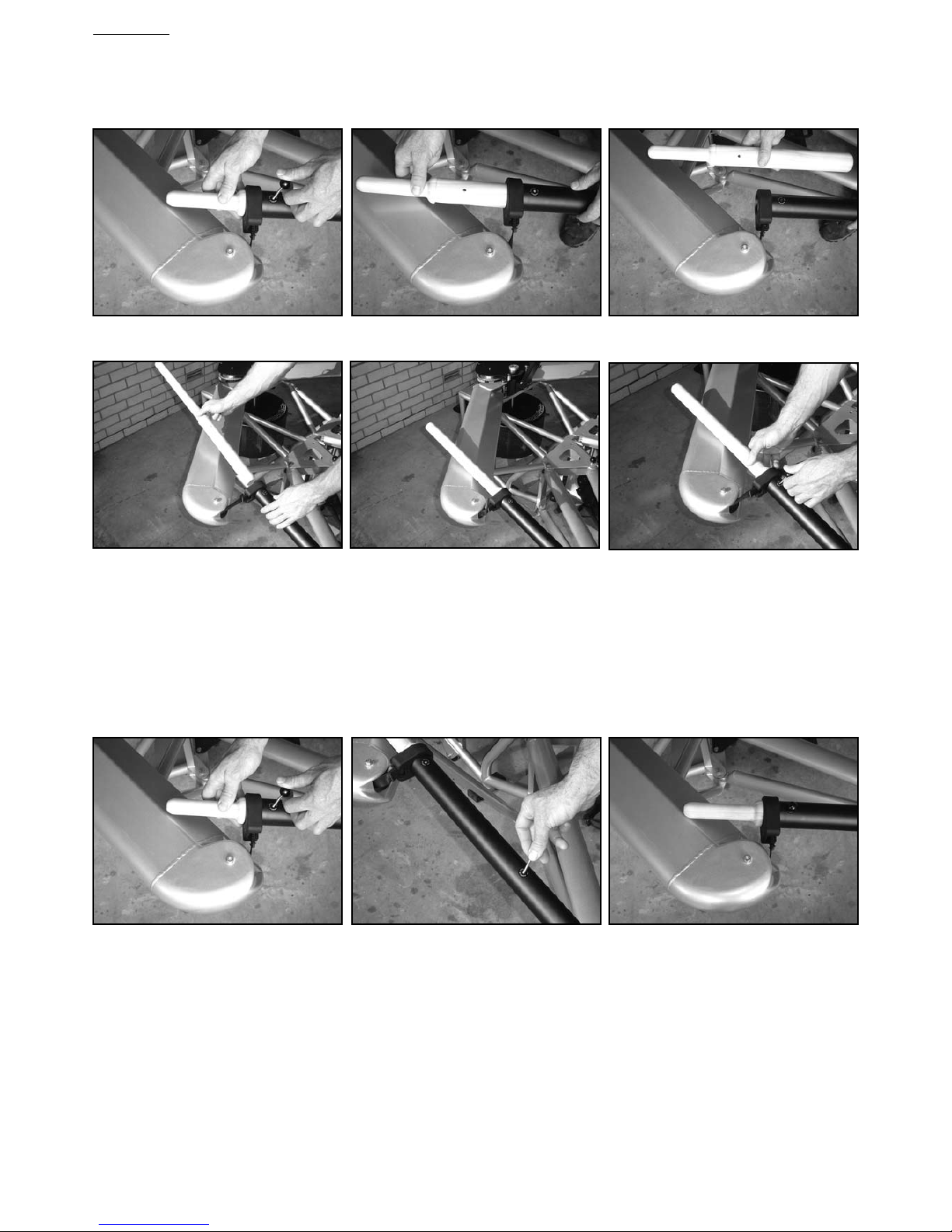
The Oartec is shipped in the sculling configuration but if sweep rowing is the preferred configuration, the
oar handles and pivot position need to be changed accordingly (see Changing the Handles and Changing
the Oar Pivot Span Position in the Operation section of the manual). The sweep handles are shipped in the
large box packaging the front assembly.
Move the footstretcher to the preferred position for either sweep or sculling (see Moving the
Footstretcher). The positions are numbered for quick reference and most users will have a different
footstretcher position for sweep and sculling.
Take a few easy and slow strokes to get used to the feel of the machine. If sculling, the oar heights can
be configured to have Left over Right clearance between the handles, which makes it easier to move the
hands through the crossover during the recovery (see Changing the Oar Height). Choose between having
the oar handles free to rotate in the oar shaft to simulate feathering or keep them in the locked position.
The resistance is changed by moving the lever at the top front of the flywheel housing and the positions
are numbered for quick reference (see Changing the Resistance). Note that the recommended
resistance range for rowing and sculling differ.
The workout monitor takes 4 AA batteries to power the display and needs to be manually turned on by
pressing the On/Off button (for more information and functions see the Workout Monitor section of the
manual).
When the Oartec is assembled in the factory prior to shipping, the bungy tension is set to compensate
for the initial stretch of the bungy. After shipping and initial use of the machine the bungy will stretch and
then settle in but this tension might have to be retuned for optimal performance. This is a simple
procedure and will only need adjustment in small increments (for more information see Adjusting the
Bungy Tension in the Maintenance section of the manual)
OPERATION

FOLDING
The Oartec Rowing Simulator has been designed to allow the outriggers and drive arms to fold inwards
and reduce the overall width of the simulator when not in use by two thirds for easy relocation, storage
or space saving. This is a simple process and should take less than 1 minute to complete.
To fold down the Oartec follow the procedure set out below.
Loosen the T Knob that connects the drive arm with the brace arm. Pull the brace arm from under the
drive arm and fold inwards toward the flywheel.
Remove the outrigger locking pin and push the drive arm and outrigger inwards simultaneously until the
drive arm locks into position and the outrigger is parallel with the seat rail.
Repeat the process with the opposite side
Place the outrigger locking pin in the frame plate hole
to secure the outriggers when in the folded position.
OPERATION

UNFOLDING
Pull the indexing plunger underneath the drive assembly plate to release the drive arm and remove the
outrigger locking pin to free the outrigger. Swing both the arm and outrigger outwards simultaneously.
Insert the outrigger locking pin to lock the outrigger in the operational position. Swing the brace arm into
position and connect with the drive arm.
Repeat the unfolding procedure for the opposite side.
OPERATION

CHANGING THE RESISTANCE
The resistance on the Oartec is provided solely by air resistance and is increased or decreased by
changing the amount of air that enters the flywheel housing system. A shutter mechanism is used to
open or close the air intake area and control the air flow. To adjust the resistance, simply the move the
lever at the front of the shutter mechanism to the left or right.
The total range of resistance is numbered for quick reference and the recommended resistance for
rowing is between positions 10 and 6 and between positions 1 and 5 for sculling. The higher the number
the harder the resistance.
ADJUSTING THE FEET HEIGHT
The feet height on the footstretcher can be easily adjusted higher or lower to a preferred height setting.
To adjust the feet height, pull the top of the plastic Heelflex until it releases from the locking buttons and
slide the Heelflex up or down through the foot bracket into position. Check that both left and right feet
heights are the same by counting the holes above the foot bracket.
The holes are also numbered for quick reference.
OPERATION

MOVING THE FOOTSTRETCHER
The footstretcher can be moved forward or back along the seat rail to allow for all sizes of rower,
correct position of the handles at the finish or a preferred set up. The positions are numbered for
quick reference.
For sweep rowing it is recommended to begin with the footstretcher in the middle of the adjustment
range (position 5) to be the right distance ‘behind the pin’, and then adjust the footstretcher to the
preferred setting according to height and leg length of the rower.
For sculling the position of the footstretcher will be determined by the leg length of the rower and the
preferred separation of the oar handles at the finish of the stroke. Taller rowers (+6ft) will need the
footstretcher set between positions 6 - 10 and shorter rowers positions 2 - 6 as a rough starting guide.
The footstretcher is secured in place on the seat rail by 2 clamping knobs at top front and 1 clamping
lever underneath at the rear of the centre box. To move the footstretcher, follow the procedure set out
below.
Loosen the clamping knobs located at the top front of the footstretcher center box.
Loosen the locking lever located underneath the seat rail by rotating anticlockwise 3 to 4 turns.
Lift the footstretcher assembly high enough to clear the bolt heads on the seat rail cover plate.
Move the footstretcher assembly forward or back along the rail to the desired position.
Make sure the holes on the footstretcher center box line up with the button heads before securing the
top knobs and bottom lever firmly but not overtight.
OPERATION

CHANGING THE OAR HANDLES
To change between the sweep or sculling oar handles first remove the locking pin, which holds the
handles in the oar shaft.
Remove the handle from the oar shaft and insert the alternative handle. Replace the locking pin.
Remember that once the handles have been changed, the pivot position of the oar in the outrigger must
be changed to correspond with rowing or sculling.
FEATHERING THE OAR
To simulate the feathering of the oar remove the locking pin which will allow the oar handle to rotate
inside the oar tube.The locking pin can be stored in the hole halfway along the oar shaft when not being
used to lock the handle.
OPERATION

CHANGING THE OAR PIVOT SPAN POSITION
There are 2 oar pivot span positions on the outrigger which provide the correct span for rowing or
sculling – the inside hole for sculling and the outside hole for sweep rowing.
To change from one span position to the other, lift and remove the oar from the span hole and insert it in
the correct hole for sweep or sculling. Try to avoid placing downward pressure on the oar handle as the
oar is being removed from the pivot hole as this will engage the spring in the oar pivot end of the oar and
make it more difficult to remove the oar.
CHANGING THE OAR HEIGHT
The oar pivot contains a mechanism to adjust the draw height of the oars to the preference of the rower.
The oars can be set to 2 draw heights - HIGH or LOW. To change between HIGH or LOW height settings
pull the oar away from the drive arm and raise the oar handle up 10 degrees to release the pressure on
the height spring. Rotate the button knob on the oar pivot 90 degrees to the desired setting and start
rowing.
In addition to this adjustment, there is a 2omm plastic spacer located on the oar pivot shaft which can be
removed to lower the overall oar height even more if necessary.
To set the oar heights for sculling where there is clearance between the LEFT oar handle and RIGHT oar
handle, remove the 20mm plastic spacer underneath the RIGHT HAND oar pivot only and set the oar
height to HIGH on the LEFT oar and LOW on the RIGHT oar. The 20mm spacer can be stored on the oar
pivot shaft underneath the outrigger casting when not used on the top side of the outrigger.
SWEEP ROWING PIVOT POSITION SCULLING PIVOT POSITION
OPERATION

MOVING
The Oartec has wheels for easy relocation and can be moved in either the folded or unfolded mode. When
folded the Oartec is narrow enough to fit through doorways to be moved from room to room or stored.
To move the location of the machine carefully raise the seat rail above a 30 degree angle to engage the
wheels on the ground.
At approximately 45 degrees to the floor, the machine is resting completely on the wheels and can be
steered to a different location for storage or use.
STORAGE
When not in use the Oartec can be stored stood vertically upright to maximize the amount of space
available in the room.
Care must be taken to ensure that the Oartec is on solid and level ground and away from the general
traffic flow of the room when stood vertically to prevent the simulator being toppled over by accident.
Due to the substantial weight of the simulator and the possibility of injury and damage if it were to fall, it is
very important to check the stability of the machine before leaving it in the upright position.
OPERATION

OARTEC WORKOUT MONITOR
The Oartec Workout Monitor displays speed, time, distance and stroke rate. In addition, there are 2 more
fields that can be activated to display average speeds or technical data such as stroke length, drive ratio
and heart rate.
This diagram shows the buttons, total icons and functions available on the display screen.
The operation and functions of the workout monitor are set out on the following pages.
ON/
OFF
DIST
SPEED
REST
TECH
READY
AV
MEMORY
TIME
INTERVAL
SCULL
SWEEP
WORKOUT MONITOR

OPERATING INSTRUCTIONS
ON/OFF
Press the ON/OFF button once to turn the display on or off.
The monitor display will automatically turn off after 90 seconds of no use to save battery life.
SETTING THE TIME
Clear the display screen by turning the monitor display OFF and then ON again using the ON/OFF button.
Press the TIME button.
Time digits will flash for setting the desired time.
Program in the set Time using the arrow buttons. Scroll through the digit values using the button and
to move to the next digit press the button.
When the desired workout Time is set, press the READY button.
Begin rowing and the set time will count down to zero.
At the end of the workout the Distance field will display the total distance rowed for the programmed
distance.
Just prior to beginning or while rowing, press the DIST button if wanting to view Projected Distance
(PROJ) in the Distance field in the bottom right of the display.
Press the DIST button again to return to Elapsed Distance mode.
SETTING THE DISTANCE
Clear the display screen by turning the monitor display OFF and then ON again using the ON/OFF button.
Press the DIST button.
Distance digits will flash for setting the desired Distance in meters.
Program in set Distance using ARROW buttons.
When the desired workout Distance is set, press READY button.
Begin rowing and the distance will count down to zero.
At the end of the workout the Time field will display the total time taken for the programmed distance.
Just prior to beginning or while rowing, press the TIME button if wanting to view Projected Time in the
Time field in the top left corner of the display.
Press the TIME button again to view Elapsed Time.
SPEED
Units of SPEED able to be displayed in the Speed field (center right) are time/500m, m/s, km/hr, mil/hr
and Power in watts.
Press the SPEED button for the selection of the preferred unit of Speed.
To change the unit of Speed while rowing, simply press the SPEED button.
Start rowing to begin the workout.
The speed value will be shown after the first stroke.
Speed will be calculated for every stroke and will be updated at the finish of each stroke drive phase.
AV (Average data)
The default display does not illuminate the AV field located in the top right of the display when the monitor
display is turned ON.
To illuminate the AV window press the AV button and the AV window will display the Average Speed for
the currently selected Speed unit.
If wanting to display a different Average Speed unit, press the AV button until the desired unit is shown.
Eg displaying Speed in time/500m and Average in Av km/hr at the same time.
Start rowing to begin workout and an Average Speed value will be shown after the first stroke.
Average Speed will be calculated from the beginning of the workout and will be updated at the finish of
each stroke drive phase.
WORKOUT MONITOR
ON/
OFF
DIST
SPEED
REST
TECH
READY
AV
MEMORY
TIME
INTERVAL
ON/
OFF
DIST
SPEED
REST
TECH
READY
AV
MEMORY
TIME
INTERVAL

WORKOUT MONITOR
STROKE COUNT
To view the STROKE COUNT for an elapsed or programmed workout press the AV button and scroll
through the units until COUNT appears on the display.
TECH (Technical data)
The default display does not illuminate the TECH field when the monitor is turned ON. To display the TECH
field press the TECH button.
Technical functions that can be calculated and displayed in the TECH field are DRIVE RATIO, AVERAGE
SPM, STROKE LENGTH, DRAG, and HEART RATE.
Select the preferred TECH function by pressing the TECH button. If the HR receiver is plugged in, it will
override all other functions in this field.
Stroke Length (SL) is the drive length of the stroke represented numerically as a reference value.
Drive Ratio (DR) is the ratio of the drive phase to the recovery phase, ie. if the Drive time is 1 second and
the recovery time is 2 seconds, the ratio displayed will be 1:2.0
Average Strokes Per Minute (Av/SPM) is the average stroke rating since the beginning of the workout.
The Heart Rate (HR) display function allows the user to view their heart rate on the monitor. To use this
function, a standard Polar HR Chest Transmitter and a plug in Polar receiver for rowing machines is
required. These are available from Oartec or a Polar supplier.
Drag is the deceleration factor of the flywheel at a given resistance setting. As the resistance is changed,
by moving the lever on the top of the flywheel housing, the drag will automatically calculate the change
in resistance and recalibrate the speed values accordingly. The drag display allows the user to set the
resistance to a predetermined drag value to use when needing to be able to compare scores from one
simulator to another.
MEMORY
When a set workout is completed the Total Distance or Total Time will be displayed on a frozen screen.
During the workout, each split, set at a default of 500m intervals, is recorded for the duration of the
workout.
To access the data recorded for each split of a set workout, press the MEMORY button to scroll through
and view each of the recorded splits.
The first screen displayed will show the Total values for the set workout.
The INTERVAL digit value will read F to represent the Finished Totals. As the user scrolls through the
splits the interval field will display a number to indicate which split of the workout the user is viewing.
The number assigned to each split is in order from beginning to last. For example, the Interval 01
represents the first 500m (default) of the set workout.
Alternatively the user can scroll forward or back through the recorded data by using the
ARROW buttons.
To view the Total values for other units, press the AV button until the desired unit value is shown.
Default unit for each interval will be Av Time/500m.
To view the other unit values for each interval, press the AV button to view: Av Speed in Time/500m,
M/S, KM/HR, M/HR, Power in WATTS, and Stroke Count.

HEART RATE MONITORING
The Oartec workout monitor uses the Polar heart rate transmitter and receiver to display the heart rate
in the TECH field on the screen. This function overrides all other functions in this field.
To monitor heart rate during a workout plug the Polar receiver into port 2 located next to the flywheel
sensor cable. Once the receiver accepts the signal the heart rate will display and the heart icon flash for
each heartbeat.
PORTS
Located on the back of the monitor there are four ports for specific cable connection.
The first small port is for the flywheel sensor cable (labelled Sensor Port)
The second small port is for the Polar Heart Rate receiver.(labeled HR Port)
The USB port is for connecting the monitor to a computer.
The Network port is for connecting to other Oartec monitors.
BATTERIES
The Oartec Workout Monitor takes 4 AA standard batteries and access to the battery compartment is
by sliding open the battery cover as shown.
WORKOUT MONITOR

MAINTENANCE CHECKLIST
The Oartec requires regular maintenance to maintain a safe and prolonged operation life.
Oartec recommends the following checks and procedures.
Regularly check the condition of the drive straps and replace immediately if there is significant sign of
wear of the loop attachment to the oar or if the strap is cut or worn along it’s length at any point.
Use of the simulator with a worn or weakened drive strap is likely to result in failure of the drive strap and
may cause injury to the user. Contact the distributor to purchase replacement drive straps.
Similarly check the return straps and replace if worn or damaged.
Periodically examine the drive system beneath the faring for any wear on the toothed rubber drive belts
or on the drive and return straps winding onto the drive spool. This check can be performed with a visual
examination through the opening between the faring and the arm when the drive arms are folded into the
stored position. Replace if worn or damaged.
Keep the frame, seat rail and flywheel housing clean and free of dust, sweat and other materials.
Wipe any sweat off the seat rail and frame after daily use using a soft cloth so as to not scratch
or damage the finish.
Periodically open the flywheel housing and clean the flywheel and housing mesh of dust using a vacumn
cleaner or soft cloth.
TROUBLESHOOTING
The drive strap fails to return completely into the arm.
Increase the tension of the bungy in small increments of 2.5cm to 5cm (1” to 2”). See TENSIONING THE
RETURN BUNGY in the Maintenance section of the manual.
Check the condition of the return strap that it has not become worn or frayed preventing smooth travel
of the return block pulley inside the arm. Replace if necessary following the procedure set out in Part 3
and Part 4 of REPLACING THE DRIVE STRAPS in the Maintenance section of the manual.
Check the position of the return block pulley inside the drive arm. Refer to Part 4 of REPLACING THE
DRIVE STRAPS.
Check that the return strap or bungy is not twisted inside the drive arm. If the bungy is twisted the return
bungy rigging plate may need to be removed but most times the twist in the bungy can be fixed by
reaching inside the arm and rolling the bungy straight again. If the return strap is twisted remove the
strap from the tensioner and reattach with the twist removed. Follow the return strap tension procedure
in Part 4 of REPLACING THE DRIVE STRAPS.
Strange sounds coming from inside the drive arms.
Check that the bungy or return strap are not twisted inside the drive arm causing the return block pul-
ley to scrape on the inside of the drive arm. Check that the rigging of the return strap is correct and the
bungy is straight.
The rolling of the seat along the seat rail becomes bumpy or noisy.
Clean the seat rail and seat wheels with a soft cloth and light spray detergent (kitchen cleaner or similar)
to remove any dirt and particles from the surfaces of the seat rail cover and seat wheels.
Sounds of objects moving around inside the flywheel housing.
Remove the lower flywheel housing from the machine and clean out any objects that may have fallen into
the housing via the top intake vent.
If experiencing difficulties with any of these maintenance procedures or have another problem not
listed, please contact the distributor or Oartec direct at [email protected] and we will advise the best
solutions to help.
MAINTENANCE

MAINTENANCE
TENSIONING THE RETURN BUNGY
To tension the return bungy follow the procedure set out below.
Loosen the T Knob that connects the drive arm with the brace arm and fold the drive arm inwards until it
locks into place parallel with the seat rail.
The locking mechanism for the return bungy protrudes from the end of the drive arm. Hook the open end
of the bungy from where it is tucked into the arm.
Place a finger on the bungy inside the first locking hole to secure the bungy tension then push the bungy
through the end locking hole to make a loop. Push this loop through the second locking hole until the loop
is on the outside of the locking mechanism.
Place a finger through the outside loop and pull the bungy through the first locking hole to increase the
tension on the bungy return. Maintain enough pressure on the inside of the bungy to prevent the bungy
from slipping back through the first hole. Push the outside loop back through the second locking hole and
then back through the third locking hole. Tuck the open end of the bungy back into the arm.
Adjust the bungy tension only in small increments of 2.5cm to 5cm (1” - 2”) at a time. This is enough
adjustment to have an influence on the bungy tension and improve the returning capacity of the return
system. Test the rate of return by rowing a few strokes and repeat the process on the opposite side by
matching the exposed length of the open end of the bungy to keep the return tension equal.

MAINTENANCE
REPLACING THE DRIVE STRAPS
If it becomes necessary to replace the drive strap webbing due to he drive strap becoming worn
or frayed please follow the procedure set out below.
PART 1 - DISCONNECTING THE RETURN SYSTEM
Fold one or both of the drive arms to aid in the removal of the faring.
Undo the 2 nuts at the front top of the faring holding the faring in place. Lift the faring off the machine
and put it in a safe place while working on the machine.
Release the tension on the return strap by loosening the lock nut for the return strap tensioner under-
neath the frame plate, and then remove the return strap webbing from the tensioner.
Undo the nut at the outer underneath end of the drive arm and the nut inside the open frame end of the
drive arm to release the return bungy rigging frame.
Remove the return bungy rigging frame from the drive arm and put in a safe place away from the working
repair zone of the machine.
Check the condition of the return strap webbing. If still in good condition it can remain attached to the
drive spool pulley. If needing replacing, remove the return strap webbing from the spool pulley at this time
using a 3mm Allen key to loosen the grub screw that locks the return strap clamping pin.

PART 2 - REMOVING THE OLD AND REATTACHING THE NEW DRIVE STRAPS
Disconnect the current drive strap from the machine at the oar handle by undoing the locking bolt
concealed by the rubber cover using a 5mm Allen key and at the drive spool pulley by undoing the grub
screw that locks the drive strap clamping pin using an 3mm Allen key.
Attach the replacement drive strap at the oar end first while paying attention to the orientation of the
rubber cover in relation to the oar tube end and the drive strap.
Once attached to the oar, thread the drive strap into the drive arm around the outside of the pulley at the
end of the drive arm. Insert the drive strap into the arm until the open end protrudes from the frame end
of the drive arm.
Visually check by looking inside down the drive arm and remove any twist from the drive strap. Hold the
drive strap in the right position to maintain zero twist in the strap and move the drive strap through the
fingers until holding the open end with about 5cm (2”) of strap extra at the end.
MAINTENANCE
Table of contents
Other OARTEC Home Gym manuals
Popular Home Gym manuals by other brands

Hoist Fitness
Hoist Fitness ROC-IT RS-1101-A owner's manual

Crivit
Crivit 304119 Instructions for use

Proxomed
Proxomed Compass 600 user manual

Weider
Weider 200 Power Tower Bench Manual Del Usuario

Tko Sports Group
Tko Sports Group 833CPR Assembly manual and user guide

Trojan
Trojan Stealth 3100 owner's manual