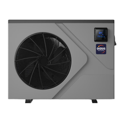
Oasis C8b Service manual

SWIMMING POOL HEAT PUMP UNIT
Installation & Instruction Manual


CONTENTS
1. Preface
2. Specifications
2.1 Performance Data of Swimming Pool Heat Pump Unit
2.2 Dimensions for Swimming Pool Heat Pump Unit
3. Installation and Connection
3.1 Installation of System
3.2
3.3 How Close to Your Pool?
3.4
3.5
3.6 Initial Start-up of the Unit
4. Usage and Operation
4.1
4.2
4.3
5. Maintenance and Inspection
5.1
5.2 Malfunction table
6.Appendix
Spa Heat Pumps Location
Spa Heat Pumps Plumbing
Spa Heat Pumps Electrical Wiring
Function of wire controller
The controller usage
Parameter table
Maintenance
6.4 Cable specification
6.1 Connection of PCB Illustration
6.2 Connections Explanation
6.3 Caution & Warning
6.5 Explosive view of the unit
1
2
2
4
6
6
7
7
8
9
9
10
10
12
19
20
20
21
22
22
22
23
24
25

1. PREFACE
The unit canonly be repairedby qualified installercenter personnel oran authorised
dealer.
Maintenance and operationmust be carriedout according tothe recommended timeand
frequency, as stated inthis manual.
Use genuine standardspare parts only. Failure tocomply with theserecommendations
will invalidate the warranty.
SWIMMING POOL HEAT PUMP Unit heats the spa water and keeps the temperature
constant.
This type of pump has the following characteristics:
1. Durable
Withstand prolonged exposureto corrosives suchas chlorine. The heat exchangeris
made of pvc& titanium tubewhich can .
2. Installation flexibility
The unit canbe installed outsideor inside ofthe Spa.
3. Quiet operation
The unit comprisesan efficient rotary/ scroll compressorand a low-noisefan motor,
which guarantees its quiet operation.
4. Advanced controlling
The unit includesmicro-computer controlling, allowing all operation parameters to be set.
Operation status canbe displayed on the wire controller.
1
In order to provide our customers with quality, reliability and versatility, this
product has been made to strict production standards. This manual
includes all the necessary information about installation, debugging,
discharging and maintenance. Please read this manual carefully before
you open or maintain the unit. The manufacturer of this product will not be
held responsible if someone is injured or the unit is damaged, as a result of
improper installation, debugging, or unnecessary maintenance. It is vital
that the instructions within this manual are adhered to at all times. The unit
must be installed by qualified personnel.

2
2.SPECIFICATION
2.1 Performance data of Swimming Pool Heat Pump Unit
REFRIGERANT :R407C
Unit
Heating Capacity
Heating Power Input
Running Current
Power Supply
Compressor Quantity
Compressor
Fan Quantity
Fan Power Input
Fan Rotate Speed
Fan Direction
Noise
Water Connection
Water Flow Volume
Water Pressure Drop(max)
Unit Net Dimensions(L/W/H)
Unit Shipping Dimensions(L/W/H)
Net Weight
Shipping Weight
Model
kW
BTU/h
kW
A
W
RPM
dB(A)
inch
3
m/h
kPa
mm
mm
kg
kg
Oasis C13b
13.2
45000
2.6
11.8
230V~/50Hz
1
Rotary
1
120
850
Horizontal
54
1.5
4.5
10
1000 420 650
1060 440 710
65
72
REFRIGERANT :R407C
Unit
Heating Capacity
Heating Power Input
Running Current
Power Supply
Compressor Quantity
Compressor
Fan Quantity
Fan Power Input
Fan Rotate Speed
Fan Direction
Noise
Water Connection
Water Flow Volume
Water Pressure Drop(max)
Unit Net Dimensions(L/W/H)
Unit Shipping Dimensions(L/W/H)
Net Weight
Shipping Weight
Model
kW
BTU/h
kW
A
W
RPM
dB(A)
inch
3
m/h
kPa
mm
mm
kg
kg
Oasis C17b
17.5
60000
3.5
15.9
230V~/50Hz
1
Scroll
1
120
850
Horizontal
54
1.5
6.0
10
1120
470 850
1200
480 1010
100
108
Oasis C8b
8.8
30000
1.7
7.7
230V~/50Hz
1
rotary
1
120
850
horizontal
51
1.5
3.0
10
1000 420 650
1060 440 710
60
67
Oasis H13b
13.2
45000
2.6
11.8
230V~/50Hz
1
Rotary
1
120
850
Horizontal
54
1.5
4.5
10
1000 420 650
1060 440 710
65
72
Oasis H17b
17.5
60000
3.5
15.9
230V~/50Hz
1
Scroll
1
120
850
Horizontal
54
1.5
6.0
10
1120 470 850
1200 480 970
100
108
Oasis C25b
25
90000
5.0
22.7
230V~/50Hz
1
Scroll
2
120 2
850
Horizontal
56
1.5
9.0
12
1120 470 1240
1200 490 1380
132
145

3
2.SPECIFICATION
2.1 Performance data of Swimming Pool Heat Pump Unit
REFRIGERANT :R407C
Unit
Heating Capacity
Heating Power Input
Running Current
Power Supply
Compressor Quantity
Compressor
Fan Quantity
Fan Power Input
Fan Rotate Speed
Fan Direction
Noise
Water Connection
Water Flow Volume
Water Pressure Drop(max)
Unit Net Dimensions(L/W/H)
Unit Shipping Dimensions(L/W/H)
Net Weight
Shipping Weight
Model
kW
BTU/h
kW
A
W
RPM
dB(A)
inch
3
m/h
kPa
mm
mm
kg
kg
Oasis C35T-Vb
35
120000
7.1
12.7
380V/3N~/50Hz
2
Scroll
2
200 2
850
Horizontal
61
2.0
12
15
1490 735 1130
1520 790 1340
244
284
Oasis C25Tb
25
90000
5.0
8.3
380V/3N~/50Hz
1
Scroll
2
120 2
850
Horizontal
56
1.5
9.0
12
1120 470 1240
1200 490 1380
130
140
REFRIGERANT :R410A
Unit
Heating Capacity
Heating Power Input
Running Current
Power Supply
Compressor Quantity
Compressor
Fan Quantity
Fan Power Input
Fan Rotate Speed
Fan Direction
Noise
Water Connection
Water Flow Volume
Water Pressure Drop(max)
Unit Net Dimensions(L/W/H)
Unit Shipping Dimensions(L/W/H)
Net Weight
Shipping Weight
Model
kW
BTU/h
kW
A
W
RPM
dB(A)
inch
3
m/h
kPa
mm
mm
kg
kg
Oasis C21b
22
75000
4.25
19.32
230V~/50Hz
1
Scroll
2
120 2
850
Horizontal
56
1.5
7.5
12
1120 470 1240
1200
490 1410
135
152
Oasis C50T-Vb
55
187000
11.6
20.7
380V/3N~/50Hz
2
Scroll
2
390 2
900
Horizontal
61
2.0
19.5
15
1490 735 1130
1520 790 1340
300
325
EH9b
9.2
31400
1.65
7.50
230V /50Hz
1
rotary
1
120
850
horizontal
51
1.5
3.0
10
1002 455 658
1130 470 695
61
71

4
2.2 The dimensions for Swimming Pool Heat Pump Unit
2.SPECIFICATION
Models: Oasis C8b/Oasis C13b/Oasis H13b/Oasis C17b/Oasis H17b
Models: Oasis C21b/Oasis C25b/OasisC25Tb
Water Inlet
Water Outlet
A
E
D
C
B
TYPE
B
A
C
D
SIZE
E
unit mm
Oasis C8b/C13b/H13b
650
1000
700
420
400
255
101
Horizontal vision
Vertical vision
Oasis C17b/H17b
850
1120
720
470
440
400
97
TYPE
B
A
C
D
SIZE
1240
1120
720
470
440
475
95
E
Unit mm
Oasis C21b/C25b/C25Tb
A
E
D
C
B
Horizontal vision
Water Inlet
Water Outlet
Vertical vision
FG
F
G
F
G
GF

5
2.SPECIFICATION
Models: Oasis C35T-Vb/OasisC50T-Vb
Models: EH9b
1002
658
430
455
630
Water Inlet
Water Outlet
Horizontal vision
Vertical vision
1130
1490
1464
480
735
Water inlet
Water outlet
Drainage
Horizontal vision
Vertical vision
255102.5
88 120

6
Installation items:
The factory onlyprovides the heatpump unit; theother items inthe illustration are
necessary spare partsfor the watersystem ,provided byusers or theinstaller.
3.1 Installation illustration
3.INSTALLATION ANDCONNECTION
Chlorinator cell
Water outlet
Pool
Valve
Water supply
Water inlet Water pump
Sand filter
(or other type filter)
By-pass valve
Special Notes:
If the heatpump is usedto heat thespa, then theparts will notstrictly like whatshown as
above, please makesure the waterloop is clearand enough.

7
The unit will perform well in any outdoor location provided that the following three factors are present .
1. Fresh Air - 2. Electricity - 3. filter piping
DO NOT place the unit in an enclosed area with a limited air volume, where the units
discharge air will be re-circulated. DO NOT place the unit to shrubs which can block air inlet. These
locations deny the unit of a continuous source of fresh air which reduces it efficiency and
may prevent adequate heat delivery.
3.2 Spa Heat Pumps Location
3.3 How Close To Your spa?
3.INSTALLATION ANDCONNECTION
Air inlet
Air outlet
2500mm
700mm
300mm
500mm
700mm
Normally, the longer thedistance from the spa, the greaterthe heat loss from the piping.It
is recommended to install the heatpump near the spa.

3.4 Spa Heat Pumps Plumbing
Location: Connect the unit in thepool pump discharge (return) line downstreamof all filter
and pool pumps, and upstream ofany chlorinators, ozonators or chemical pumps.
Standard model have slip glue fittingswhich accept 40mmNB PVC pipe for connection to
the pool or spa filtration piping.By using a 50 NB to40NB you can plumb 50NB PVCpiping
straight into the unit.
Give serious consideration to adding aquick coupler fitting at the unitinlet and outlet to allow
easy draining of unit for winterizingand to provide easier access shouldservicing be
required.
Condensation: Since theHeat pump coolsdown the airabout 4 -5 , water maycondense on
the fins ofthe horseshoe shapedevaporator. Ifthe relative humidityis very high,this could
be as muchas several litresan hour.The water will run downthe fins intothe basepan and
drain out throughthe barbed plasticcondensation drain fittingon the sideof the basepan.
This fitting isdesigned to accept3/4" clear vinyltubing which canbe pushed onby hand and
run to asuitable drain. Itis easy tomistake the condensationfor a waterleak inside theunit.
NB: Aquick way to verify that the water is condensation is to shut off the unit and keep the
pool pump running.If the waterstops running outof the basepan,it is condensation.AN
EVEN QUICKER WAY IS to TEST THE DRAIN WATER FOR CHLORINE - if the is no chlorine
present, then it'scondensation.
3.INSTALLATION ANDCONNECTION
To Sp a
From pump
PVC COUPLER
RECOMMENDED(Provided)
The Spa HeatPumps exclusive ratedflow titanium heatexchanger requires nospecial
plumbing arrangements exceptbypass(please set theflow rate accordingto the nameplate).
The water pressuredrop is lessthan 10kPa atmax. Flow rate.Since there isno residual
heat or flameTemperatures, The unit does not need copper heat sink piping. PVC pipe can
be run straightinto the unit.
8
Horizontal vision

9
3.5 Spa Heat Pumps Electrical Wiring
NOTE: Althoughthe unit heatexchanger is electricallyisolated from therest of theunit, it
simply prevents theflow of electricityto or fromthe pool water. Grounding the unit is still
required to protectyou against shortcircuits inside theunit. Bonding isalso required.
3.INSTALLATION ANDCONNECTION
3.6 Initial startup of the Unit
NOTE- In orderfor the unitto heat the pool or spa, the filter pump must be running to
circulate water throughthe heat exchanger.
Start up Procedure- Afterinstallation is completed, you should follow these steps:
1. Turnon your filterpump. Check for water leaks and verify flow to and from the pool.
2. Turnon the electricalpower supply to the unit, then press the key ON/OFF of wire
controller, Itshould start in several seconds.
3. Afterrunning a fewminutes make sure the air leaving the top(side) of the unit is
cooler(Between 5-10 )
4. With theunit operating turnthe filter pump off. The unit should also turn off automatically,
5. Allowthe unit andpool pump to run 24 hours per day until desired pool water temperature
is reached. Whenthe water-in temperature reach setting, The unit just
shuts off. The unit will now automatically restart (as long as your pool pump is running)when
the pool temperaturedrops more than 2 below set temperature.
Water Flow Switch - the unit is equipped with a flow switch that turns it on whenthe pool
pump is runningand shuts itoff when the pump shuts off. This switch is thesame type usedin
all gas poolheaters and isfactory adjusted for normal pool installations. If the pool water
level is morethan a fewfeet above or below the thermostat knob of the unit, your dealer may
need to adjustit at initialstartup.
Time Delay- The unit is equipped with a 3 minute built-in solid state restart delay includedto
protect control circuitcomponents and to eliminate restart cycling and contactor chatter.
This time delaywill automatically restart the unit approximately 3 minutes after each control
circuit interruption. Evena brief power interruption will activate the solid state 3 minute
restart delay andprevent the unit from starting until the 5 minute countdown is completed.
The unit hasa separate molded-in junction box with a standard electrical conduit nipple
already in place.Just remove the screws and the front panel, feed your supply lines in
through the conduitnipple and wire-nut the electric supply wires to the three connections
already in thejunction box (four connections if three phase). To complete electrical hookup,
connect Heat Pumpby electrical conduit, UF cable or other suitable means as specified (as
permitted by localelectrical authorities) to a dedicated AC power supply branch circuit
equipped with theproper circuit breaker, disconnect or time delay fuseprotection.
Disconnect -A disconnectmeans (circuit breaker , fused or un-fused switch) should be
located within sightof and readily accessible from the uni, This is common practice on
commercial and residentialair conditioners and heat pumps. It prevents remotely-energizing
unattended equipment andpermits turning off power atthe unit whilethe unit isbeing
serviced.
Disconnect

Disconnect
10
4. USAGE AND OPERATION
4.1Function of wire controller
Main display area
Aux. Display area
1
2
3
4
145
3
TEMP
IN
SET
C
F
A
min
ON
OFF
TEMP
OUT
VOL
MODE
SET
2
MODE
SET
Clock
1 Button function
NO Symbol Name Function
On/off
Mode
Up
Press this button can start upor shut down the unit,
cancel the current operation or backto the upper
interface
Press this buttoncan switch modesor save
parameter setting.
Press this buttoncan move upor increase
parameter value.
Press this buttoncan move downor decrease the
parameter value.
Down
5
Press this buttoncan set theclock and timer

11
4. USAGE AND OPERATION
2 Display function
A
Electric-
heating
ON
OFF
Timer on
Timer off
It is showedwhen the unitsets the timeron
It is showedwhen the unitsets the timeroff
IN
OUT
TEMP
Temperature
VOL
F
min
Fahrenheit
C
SET
Symbol Meaning Function
Cooling
Heating
Automatic
It is showedwhen the unitin cooling mode.
It is showedwhen the unitin heating modeand flashed
in defrosting.
It is showedwhen the unitin automatic mode.
Inlet water It is showedwhen the maindisplay area givesthe inlet
water temperature.(measured value)
Outlet water It is showedwhen the AUX display area gives the outlet
water temperature.(measured value)
Minute It is showedwhen the maindisplay area givesminute value
Centigrade It is showedwhen the main/AUXdisplay area
gives centigrade value
Parameter
setting It is showedwhen the parametercan be setted.
Lock It is showedwhen the keyboardis locked.
Flow It is showedwhen the maindisplay area givesthe water
flow value
It is showedwhen the main/AUX displayarea gives
temperature
It is showedwhen the main/AUXdisplay area
gives Fahrenheit value
It is showedwhen the unitin electric-heating mode.
A

12
4. USAGE AND OPERATION
4.2 The controller usage
1 Starting up and shutting down
Press
for 0.5 second
can switch
between unit
on and unitoff
Water outlet
temperature
Actual Mode display
Off unit
2 Modes switching
If it is cold/ heat unit,in the maininterface, you can switch different modes of cooling,
heating, auto modeby pressing ; If itis cold/heat andelectric heat unit,in the main
interface, you canswitch different modes of cooling,heating, auto mode,electric heating
mode, heating andelectric heating modesby pressing .
Attention The modes switchingis useless ifthe unit youbuy is single-cold/single-heat unit.
For example:
Press Press
Press
Press
TEMP
OUT
MODE
SET
TEMP
IN
C
TEMP
OUT
MODE
SET
TEMP
OUT
MODE
SET
TEMP
OUT
MODE
SET
TEMP
OUT
MODE
SET
A
TEMP
OUT
MODE
SET
TEMP
OUT
MODE
SET
MODE
SET
MODE
SET
MODE
SET
MODE
SET
MODE
SET
In the off interface, press" " for 0.5scan start up the unit, and aux. display-area shows
water outlet temperature;In the runninginterface, press" "for 0.5s canshut down theunit
and aux. display-areashows OFF .
Attention: the operationof Starting upand shutting downcan only bedone in themain interface.
For example:
Actual Mode display
Water inlet
temperature Water outlet
temperature
On unit
MODE
SET

13
4. USAGE AND OPERATION
3 Temperature setting
Press
or
Press
or to change thevalue
Press
to save value
setting
Cooling target temperature
MODE
SET
TEMP
IN
C
TEMP
OUT
MODE
SET
SET
TEMP
C
TEMP
OUT
MODE
SET
SET
TEMP
C
TEMP
OUT
MODE
SET
TEMP
IN
C
TEMP
OUT
MODE
SET
MODE
SET
4 Clock setting
In the main interface press twice Hours start to flashing and press
to increase valueor press to decrease value and press to save setting
At thesame time, minute start to flashing press to increase valueor press
to decrease value and press to save setting.
Press can not save setting parameter andback to maininterface.
Attention If there isno operation for 5s system willremember parameter setting and back
to the maininterface.
For example
In the main interface press or and the currentmode target-temperature
flashes, then press to increase thetemp.value, or press to decrease it.
Press can save settingparameter and back to the maininterface
Press can not savesetting parameter but back to themain interface
Attention If there is no operation for5s system would remember parameter setting and
back to themain interface.
For example:

14
4. USAGE AND OPERATION
TEMP
IN
C
TEMP
OUT
MODE
SET
TEMP
IN
C
TEMP
OUT
MODE
SET
Press
Hour minute Flashing
TEMP
IN
C
TEMP
OUT
MODE
SET
Flashing
Press
TEMP
IN
C
TEMP
OUT
MODE
SET
Press
or
TEMP
IN
C
TEMP
OUT
MODE
SET
Press
to save hour
value setting
TEMP
IN
C
TEMP
OUT
MODE
SET
Press
or
TEMP
IN
C
TEMP
OUT
MODE
SET
Press
to save minutevalue setting
Flashing
Flashing Flashing

15
5 Timer setting
In the main interface press hold on 2seconds and "on" is flashing, atthis time,
you can setthe timer on means the unit timer is on then press again and holdon
2 seconds and"off" is flashes you canset the timeroff means the unittimer is off .
If you wantcancel the timeroff, In the "off" flashing interface press to cancel
Attention 1) If there is no operationfor 5s system will remember clock setting andback to
the main interface.
2) By pressing " " till the "off" flashing, you can set the timer off without timer on.
TEMP
IN
C
TEMP
OUT
MODE
SET
TEMP
IN
C
TEMP
OUT
MODE
SET
ON
Press
for 2 second
TEMP
IN
C
TEMP
OUT
MODE
SET
Press
ON
Flashing
Flashing
TEMP
IN
C
TEMP
OUT
MODE
SET
ON
Flashing
press
or
TEMP
IN
C
TEMP
OUT
MODE
SET
ON
Press
Flashing
TEMP
IN
C
TEMP
OUT
MODE
SET
ON
Flashing
press
or Press
4. USAGE AND OPERATION

16
TEMP
IN
C
TEMP
OUT
MODE
SET
ON
Flashing
OFF
TEMP
IN
C
TEMP
OUT
MODE
SET
Press
ON
Press
or
OFF
TEMP
IN
C
TEMP
OUT
MODE
SET
ON
OFF
TEMP
IN
C
TEMP
OUT
MODE
SET
ON
OFF
Press
Press
or
TEMP
IN
C
TEMP
OUT
MODE
SET
ON
OFF
TEMP
IN
C
TEMP
OUT
MODE
SET
Press
ON
OFF
The timer onand off has been set
Flashing Flashing
Flashing Flashing Flashing Flashing
Flashing Flashing
4. USAGE AND OPERATION

17
6 Cancel the timer setting
Press for 2s and "ON" is flashing at this time, press to cancel the setting
of timer on;It is thesame way tocancel the settingof timer off .
For example
TEMP
IN
C
TEMP
OUT
MODE
SET
ON
OFF
The timer on/off has been set
Press
for 2s
TEMP
IN
C
TEMP
OUT
MODE
SET
ON
OFF
"ON" is flashing
TEMP
IN
C
TEMP
OUT
MODE
SET
OFF
The setting oftimer on has
been cancelled
Press
TEMP
IN
C
TEMP
OUT
MODE
SET
OFF
Press
for 4s
"OFF" is flashing
TEMP
IN
C
TEMP
OUT
MODE
SET
The setting oftimer off has
been cancelled
Press
4. USAGE AND OPERATION
This manual suits for next models
10
Table of contents
Other Oasis Heat Pump manuals