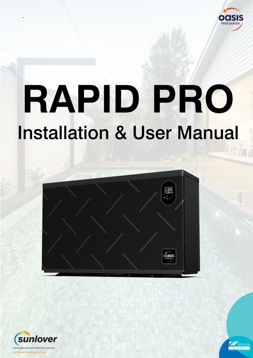
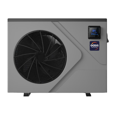
Oasis ELITE AC9 Quick guide

SWIMMING POOL HEAT PUMP UNIT
Installation & Instruction Manual

CONTENTS
1. Preface
2. Specifications
2.1 Performance Data of Swimming Pool Heat Pump Unit
2.2 Dimensions for Swimming Pool Heat Pump Unit
2.3 How to disassemble the units
2.4
3. Installation and Connection
3.1 Installation of System
3.2 Swimming Pool Heat Pumps Location
3.3 How Close to Your Pool?
3.4 Swimming Pool Heat Pumps Plumbing
3.5 Swimming Pool Heat Pumps Electrical Wiring
3.6 Initial Start-up of the Unit
4. Usage and Operation
4.1 Function of the controller
4.2 Usage of the controller
4.3 Parameter table
4.4
5. Maintenance and Inspection
5.1 Maintenance
5.2 Trouble Shooting Guide
6.Appendix
How the power cord go
Power button operating instructions
1
2
2
4
6
7
8
8
9
9
10
11
11
12
12
14
21
22
23
23
24
25

1. PREFACE
In order toprovide our customerswith quality, reliability and versatility, this product has
been made tostrict production standards.This manual includes all the necessary
information about installation,debugging, discharging and maintenance. Please read this
manual carefully beforeyou open ormaintain the unit.The manufacture of this productwill
not be heldresponsible if someoneis injured orthe unit isdamaged, as aresult of
improper installation, debugging,or unnecessary maintenance.It is vitalthat the
instructions within this manual are adheredto at alltimes. The unit must be installed by
qualified personnel.
The unit canonly be repairedby qualified installercentre , personnelor an authorised
dealer.
Maintenance and operationmust be carriedout according tothe recommended timeand
frequency, as stated inthis manual.
Use genuine standardspare parts only.
Failure to complywith these recommendationswill invalidate the warranty.
Swimming Pool HeatPump Unit heatsthe swimming poolwater and keepsthe temperature
constant. For splittype unit, The indoor unitcan be Discretelyhidden or semi-hiddento
suit a luxuryhouse.
Our heat pumphas following characteristics:
1 Durable
The heat exchanger is madeof PVC &Titanium tubewhich can withstandprolonged
exposure to swimmingpool water.
2 Installation flexibility
The unit can be installedoutdoors or indoors.
3 Quiet operation
The unit comprises an efficient rotary/ scrollcompressor and alow-noise fan motor,
which guarantees itsquiet operation.
4 Advancedcontrolling
The unit includes micro-computer controlling,allowing all operationparameters to be
set. Operation statuscan be displayedon the LCDwire controller.Remote controller canbe
chosen as futureoption.
1

2
2.SPECIFICATION
2.1 Performance data of Swimming Pool Heat Pump Unit
*** REFRIGERANT : R410A
UNIT
Heating capacity
Heating Power Input
Running Current
Power Supply
Compressor Quantity
Compressor
Fan Number
Fan Power Input
Fan Rotate Speed
Fan Direction
Noise
Water Connection
Water Flow Volume
Water Pressure Drop(max)
Unit Net Dimensions(L/W/H)
Unit Ship Dimensions(L/W/H)
Net Weight
Shipping Weight
kW
Btu/h
kW
A
W
RPM
dB(A)
mm
3
m/h
kPa
mm
mm
kg
kg
956 375 623
1010 430 635
54
65
Heating: Outdoor airtemp:24 /19 , Inlet watertemp:26
UNIT
Heating capacity
Heating Power Input
Running Current
Power Supply
Compressor Quantity
Compressor
Fan Number
Fan Power Input
Fan Rotate Speed
Fan Direction
Noise
Water Connection
Water Flow Volume
Water Pressure Drop(max)
Unit Net Dimensions(L/W/H)
Unit Ship Dimensions(L/W/H)
Net Weight
Shipping Weight
kW
Btu/h
kW
A
W
RPM
dB(A)
mm
3
m/h
kPa
mm
mm
kg
kg
1116 500 886
1200 570 900
87
104
Oasis ELITEAC14
13.8
47000
2.1
10.4
230V /50Hz
1
rotary
1
120
850
horizontal
54
40
4.5
10
Oasis ELITEAC9
9.2
31400
1.5
6.7
230V /50Hz
1
rotary
1
120
850
horizontal
51
40
3.0
10
Oasis ELITE AC18
18.2
62000
3.0
13.4
230V /50Hz
1
rotary
1
150
850
horizontal
56
40
6.0
10
956 375 623
1010 430 635
61
72

2.SPECIFICATION
2.1 Performance data of Swimming Pool Heat Pump Unit
*** REFRIGERANT : R410A
UNIT
Heating capacity
Heating Power Input
Running Current
Power Supply
Compressor Quantity
Compressor
Fan Number
Fan Power Input
Fan Rotate Speed
Fan Direction
Noise
Water Connection
Water Flow Volume
Water Pressure Drop(max)
Unit Net Dimensions(L/W/H)
Unit Ship Dimensions(L/W/H)
Net Weight
Shipping Weight
kW
Btu/h
kW
A
W
RPM
dB(A)
mm
3
m/h
kPa
mm
mm
kg
kg
Heating: Outdoor airtemp:24 /19 , Inlet watertemp:26
UNIT
Heating capacity
Heating Power Input
Running Current
Power Supply
Compressor Quantity
Compressor
Fan Number
Fan Power Input
Fan Rotate Speed
Fan Direction
Noise
Water Connection
Water Flow Volume
Water Pressure Drop(max)
Unit Net Dimensions(L/W/H)
Unit Ship Dimensions(L/W/H)
Net Weight
Shipping Weight
kW
Btu/h
kW
A
W
RPM
dB(A)
mm
3
m/h
kPa
mm
mm
kg
kg
1116 500 886
1200 570 900
87
104
Oasis ELITEAH18
18.2
62000
3.0
13.4
230V /50Hz
1
rotary
1
150
850
horizontal
56
40
6.0
10
Oasis ELITEAH14
13.8
47000
2.1
10.4
230V /50Hz
1
rotary
1
120
850
horizontal
54
40
4.5
10
Oasis ELITEAH9
9.2
31400
1.5
6.7
230V /50Hz
1
rotary
1
120
850
horizontal
51
40
3.0
10
3
956 375 623
1010 430 635
54
65
956 375 623
1010 430 635
61
72

2.2 The dimensions for Swimming Pool Heat Pump Unit
2.SPECIFICATION
4
Oasis ELITE AC9/Oasis ELITEAC14/
375
623
956
552
Water inlet
40
Water outlet
40
114 350
356
18.5
Oasis ELITE AH9/Oasis ELITEAH14

Oasis ELITEAC18
5
2.SPECIFICATION
1116
886
500
790
460
511
400116
Water inlet
40
Water outlet
40
/ Oasis ELITEAH18

6
2.3How to disassemblethe units.
2.SPECIFICATION
Attention: 1. Pleasebe careful whenhandle with thefront plate incase of damage;
2. During thisprocess, please attentionto protect the wire between thebutton
on the frontplate and electricalbox.
Pull up the
front plate
Move forward
the front plate
Takeit of

7
2.SPECIFICATION
2.
1. Pull out powercord from the electricalbox, and fix itat the place "A"as showed in thefirst
image below;
After fixing it at "A", draw it out from the bottom of the heat pump as showed in the second image.
A
Power cord
Power cord
2.4 How the power cord go

Installation items:
The factory only provides the main unit andthe water unit;the other itemsin the illustration
are necessary spareparts for thewater system ,thatprovided by usersor the installer.
3.1 Installation illustration
Attention:
Please follow thesesteps when usingfor the firsttime
1.Open valve andcharge water.
2.Make sure thatthe pump andthe water-in pipehave been filled with water.
3.Close the valveand start theunit.
ATTN: It is necessarythat the water-inpipe is higherthan the pool surface.
3.INSTALLATION AND CONNECTION
8
Chlorinator cell
Water outlet
Pool
Valve
Water supply
Water inlet Water pump
Sand filter
(or other type filter)
The schematic diagram is forreference only. Please checkthe water inlet/outletlabel on the
heat pump whileplumbing installation.

The unit willperform well inany outdoor locationprovided that thefollowing three factorsare
presented:
1. Fresh Air - 2. Electricity - 3. Pool filter piping
The unit maybe installed virtuallyanywhere outdoors. Forindoor pools pleaseconsult the
supplier. Unlikea gas heater, it has no draft or pilot light problem in a windy area.
DO NOT place the unitin an enclosedarea with alimited air volume,where the units
discharge air willbe re-circulated.
DO NOT place the unitto shrubs whichcan block airinlet. These locations deny theunit of a
continuous source offresh air whichreduces it efficiency and mayprevent adequate heat
delivery.
3.2 Swimming Pool Heat Pumps Location
Normally, the pool heatpump is installedwithin 7.5 metresof the pool.The longer the
distance from thepool, the greaterthe heat lossfrom the piping.For the mostpart ,the piping
is buried. Therefore, the heatloss is minimal for runs ofup to15 meters(15meters to andfrom
the pump =30 meters total),unless the ground is wet or the water table is high. A very rough
estimate of heatloss per 30meters is 0.6kW-hour,(2000BTU) for every 5 difference in
temperature between thepool water andthe ground surroundingthe pipe, whichtranslates to
about 3% to5% increase inrun time.
3.3 How Close To Your Pool?
9
3.INSTALLATION AND CONNECTION
Air inlet
Air outlet
300mm
700mm
300mm
500mm
700mm

3.4 Swimming Pool Heat Pumps Plumbing
Location: Connect theunit in thepool pump discharge(return) line downstreamof all filter
and pool pumps,and upstream ofany chlorinators, ozonatorsor chemical pumps.
Standard model haveslip glue fittingswhich accept 32mmor 50 mm PVC pipe for
connection to thepool or spafiltration piping. Byusing a 50NB to 40NByou can plumb40NB
Give serious considerationto adding aquick coupler fittingat the unitinlet and outletto allow
easy draining ofunit for winterizingand to provideeasier access shouldservicing be
required.
Condensation: Since theHeat pump coolsdown the airabout 4 -5 , water maycondense on
the fins ofthe horseshoe shapedevaporator. Ifthe relative humidityis very high,this could
be as muchas several litresan hour.The water will run downthe fins intothe basepan and
drain out throughthe barbed plasticcondensation drain fittingon the sideof the basepan.
This fitting isdesigned to accept20mm clear vinyltubing which canbe pushed onby hand
and run toa suitable drain.It is easyto mistake thecondensation for awater leak insidethe
unit.
NB: Aquick way toverify that the water is condensation is to shut off the unit and keep the
pool pump running.If the waterstops running outof the basepan,it is condensation.AN
EVEN QUICKER WAYIS to TEST THE DRAIN WATER FOR CHLORINE- if theis no chlorine
present, then it'scondensation.
3.INSTALLATION AND CONNECTION
10
To pool
From pump
PVC COUPLER
RECOMMENDED(Provided)
CONDENSATION
DRAIN
BARB FTG
The Swimming PoolHeat Pumps exclusiverated flow titaniumheat exchanger requiresno
special plumbing arrangementsexcept bypass(please setthe flow rateaccording to the
nameplate). The water pressure dropis less than10kPa at max.Flow rate. Since there is no
residual heat orflame Temperatures, The unit does notneed copper heatsink piping. PVC
pipe can berun straight intothe unit.

3.5 Swimming Pool Heat Pumps Electrical Wiring
NOTE: Althoughthe unit heatexchanger is electricallyisolated from therest of theunit, it
simply prevents theflow of electricityto or fromthe pool water. Grounding the unit is still
required to protectyou against shortcircuits inside theunit. Bonding isalso required.
3.INSTALLATION AND CONNECTION
3.6 Initial startup of the Unit
NOTE- In orderfor the unitto heat the pool or spa, the filter pump must be running to
circulate water throughthe heat exchanger.
Start up Procedure- Afterinstallation is completed, you should follow these steps:
1. Turnon your filterpump. Check for water leaks and verify flow to and from the pool.
2. Turnon the electricalpower supply to the unit, then press the key ON/OFF of wire
controller, Itshould start in several seconds.
3. Afterrunning a fewminutes make sure the air leaving the top(side) of the unit is
cooler(Between 5-10 )
4. With theunit operating turn the filter pump off. The unit should also turn off automatically,
5. Allowthe unit andpool pump to run 24 hours per day until desired pool water emperature is
reached. When thewater-in temperature reach setting, The unit just shuts off. The unit will
now automatically restart(as long as your pool pump is running)when the pool temperature
drops more than2 below set temperature.
Time Delay- The unit is equipped with a 3 minute built-in solid staterestart delay included to
protect control circuitcomponents and to eliminate restart cycling and contactor chatter.
This time delaywill automatically restart the unit approximately 3 minutes after each control
circuit interruption. Evena brief power interruption will activate the solid state 3 minute
restart delay andprevent the unit from starting until the 5 minute countdown is completed.
Power interruptions duringthe delay period will have no effect on the 3 minute countdown.
11
The unit hasa separate molded-injunction box witha standard electricalconduit nipple
already in place.Just remove thescrews and thefront panel, feedyour supply linesin
through the conduitnipple and wire-nutthe electric supplywires to thethree connections
already in thejunction box (fourconnections if threephase). To complete electricalhookup,
connect Heat Pumpby electrical conduit,UF cable orother suitable meansas specified (as
permitted by localelectrical authorities) toa dedicatedAC power supplybranch circuit
equipped with theproper circuit breaker, disconnect or time delay fuse protection.
Disconnect -A disconnectmeans (circuit breaker, fused orun-fused switch) shouldbe
located within sightof and readilyaccessible from theunit, This is common practiceon
commercial and residentialair conditioners andheat pumps. Itprevents remotely-energizing
unattended equipment andpermits turning off power atthe unit whilethe unit isbeing
serviced.

12
4. USAGE AND OPERATION
1.Function of controller
Main display area
Aux. Display area
1
2
3
4
145
3
TEMP
IN
SET
C
F
A
min
ON
OFF
TEMP
OUT
VOL
MODE
SET
2
MODE
SET
Clock
1 Button function
NO Symbol Name Function
On/off
Mode
Up
Press this buttoncan start upor shut downthe unit,
cancel the currentoperation or backto the upper
interface
Press this buttoncan switch modesor save
parameter setting.
Press this buttoncan move upor increase
parameter value.
Press this buttoncan move downor decrease the
parameter value.
Down
5
Press this buttoncan set theclock and timer

13
A
Electric-
heating
ON
OFF
Timer on
Timer off
It is showedwhen the unitsets the timeron
It is showedwhen the unitsets the timeroff
IN
OUT
TEMP
Temperature
VOL
F
min
Fahrenheit
C
SET
Symbol Meaning Function
Cooling
Heating
Automatic
It is showedwhen the unitin cooling mode.
It is showedwhen the unitin heating modeand flashed
in defrosting.
It is showedwhen the unitin automatic mode.
Inlet water It is showedwhen the main display area gives the inlet
water temperature.(measured value)
Outlet water It is showed when the AUX display area gives the outlet
water temperature.(measured value)
Minute It is showedwhen the maindisplay area givesminute value
Centigrade It is showedwhen the main/AUXdisplay area
gives centigrade value
Parameter
setting It is showedwhen the parametercan be setted.
Lock It is showedwhen the keyboardis locked.
Flow It is showedwhen the maindisplay area givesthe water
flow value
It is showedwhen the main/AUX displayarea gives
temperature
It is showedwhen the main/AUXdisplay area
gives Fahrenheit value
It is showedwhen the unitin electric-heating mode.
(Swimming pool unitwithout this display
4. USAGE AND OPERATION

14
2.The controller usage
2.1Starting up andshutting down
Press
for 0.5 second
can switch
between unit
on and unitoff
Water outlet
temperature
Actual Mode display
Off unit
2.2 Modes switching
If it is cold/ heat unit,in the maininterface, you canswitch different modes of cooling,
heating, auto modeby pressing .
Attention The modes switchingis useless ifthe unit youbuy is single-cold/single-heat unit.
For example:
Press Press
Press
Press
TEMP
OUT
MODE
SET
TEMP
IN
C
TEMP
OUT
MODE
SET
TEMP
OUT
MODE
SET
TEMP
OUT
MODE
SET
TEMP
OUT
MODE
SET
A
TEMP
OUT
MODE
SET
TEMP
OUT
MODE
SET
MODE
SET
MODE
SET
MODE
SET
MODE
SET
MODE
SET
In the off interface, press" " for 0.5scan start upthe unit, and aux. display-area shows
water outlet temperature;In the runninginterface, press" "for 0.5s canshut down theunit
and aux. display-areashows OFF .
Attention: the operationof Starting upand shutting downcan only bedone in themain interface.
For example:
Actual Mode display
Water inlet
temperature Water outlet
temperature
On unit
4. USAGE AND OPERATION

A
15
4. USAGE AND OPERATION
2.3 Temperature setting
Press
or
Press
or to change thevalue
Press
to save value
setting
Cooling target temperature
MODE
SET
TEMP
IN
C
TEMP
OUT
MODE
SET
SET
TEMP
C
TEMP
OUT
MODE
SET
SET
TEMP
C
TEMP
OUT
MODE
SET
TEMP
IN
C
TEMP
OUT
MODE
SET
MODE
SET
2.4 Clock setting
In the maininterface press twice Hours start toflashing and press
to increase valueor press to decrease value and press to save setting
At thesame time, minute start to flashing press to increase valueor press
to decrease value and press to save setting.
Press can not savesetting parameter andback to maininterface.
Attention If there isno operation for5s system willremember parameter setting and back
to the maininterface.
For example
In the maininterface press or and the current mode target-temperature
flashes, then press to increase thetemp.value, or press to decrease it.
Press can save settingparameter and backto the maininterface
Press can not savesetting parameter butback to themain interface
Attention If there isno operation for5s system would remember parameter setting and
back to themain interface.
For example:

4. USAGE AND OPERATION
TEMP
IN
C
TEMP
OUT
MODE
SET
TEMP
IN
C
TEMP
OUT
MODE
SET
Press
Hour minute Flashing
TEMP
IN
C
TEMP
OUT
MODE
SET
Flashing
Press
TEMP
IN
C
TEMP
OUT
MODE
SET
Press
or
TEMP
IN
C
TEMP
OUT
MODE
SET
Press
to save hour
value setting
TEMP
IN
C
TEMP
OUT
MODE
SET
Press
or
TEMP
IN
C
TEMP
OUT
MODE
SET
Press
to save minutevalue setting
Flashing
Flashing Flashing
16

17
2.5 Timersetting
In the maininterface press hold on 2 seconds and "on" is flashing, at this time,
you can setthe timer on means the unittimer is on then press again and holdon
2 seconds and"off" is flashes you canset the timeroff means the unittimer is off .
If you wantcancel the timeroff, In the "off" flashing interface press to cancel
Attention 1) If thereis no operationfor 5s system will rememberclock setting andback to
the main interface.
2) By pressing" " tillthe "off" flashing, you canset the timeroff without timer on.
TEMP
IN
C
TEMP
OUT
MODE
SET
TEMP
IN
C
TEMP
OUT
MODE
SET
ON
Press
for 2 second
TEMP
IN
C
TEMP
OUT
MODE
SET
Press
ON
Flashing
Flashing
TEMP
IN
C
TEMP
OUT
MODE
SET
ON
Flashing
press
or
TEMP
IN
C
TEMP
OUT
MODE
SET
ON
Press
Flashing
TEMP
IN
C
TEMP
OUT
MODE
SET
ON
Flashing
press
or Press
4. USAGE AND OPERATION

18
TEMP
IN
C
TEMP
OUT
MODE
SET
ON
Flashing
OFF
TEMP
IN
C
TEMP
OUT
MODE
SET
Press
ON
Press
or
OFF
TEMP
IN
C
TEMP
OUT
MODE
SET
ON
OFF
TEMP
IN
C
TEMP
OUT
MODE
SET
ON
OFF
Press
Press
or
TEMP
IN
C
TEMP
OUT
MODE
SET
ON
OFF
TEMP
IN
C
TEMP
OUT
MODE
SET
Press
ON
OFF
The timer onand off has been set
Flashing Flashing
Flashing Flashing Flashing Flashing
Flashing Flashing
4. USAGE AND OPERATION
Other manuals for ELITE AC9
1
This manual suits for next models
2
Table of contents
Other Oasis Heat Pump manuals