Oasis CO34R User manual

Rev A Date: 4.1.2013
SCC PN
20-25622
READ AND SAVE THESE INSTRUCTIONS
Model CO34R: 45 1/4”L* x 33 1/4”D x 47”H
CO44R: 47 1/4”L* x 33 1/4”D x 47”H
*Includes end panels.
OPEN REFRIGERATED SELF-SERVICE MERCHANDISER
I:\Oper Manuals\Oasis\CO34R_CO44R_20-25622.pub
888 E. Porter Road · Muskegon, MI 49441 Phone: 231.798.8888 Fax: 231.798.4960 www.structuralconcepts.com
INSTALLATION AND
OPERATING MANUAL
Model CO44R
Optional Shelf [Not
on All Cases]

2
TABLE OF CONTENTS
OVERVIEW / TYPE / COMPLIANCE / WARNINGS / PRECAUTIONS / PLUGS / WIRING ....….....…..
SHIPMENT CONDITION / DAMAGE DISCOVERED DURING DELIVERY or UNCRATING /
SHORTAGES ...………………………………………………………………………………………….
CASE REMOVAL FROM SKID [LEVELERS OR CASTERS] ...…………………………………………….
INSTALLATION …………………………………………………………………..……………………..……….
START-UP AND OPERATION ………………………...….…………………...………...…...…….…………
MAINTENANCE ………...…………………………………………………………...……..…….….…………..
MAINTENANCE, CONTINUED: HONEYCOMB AIR DIFFUSERS ………………………………………...
REFRIGERATION FUNDAMENTALS …………….………………………………..…………………....…...
SERIAL LABEL & LOCATION / TECHNICAL INFORMATION & SERVICE …………………………...…
CLEANING SCHEDULE [TO BE PERFORMED BY STORE PERSONNEL] …….……….………………
CLEANING SCHEDULE [TO BE PERFORMED BY TRAINED SERVICE PROVIDERS] ………………
PREVENTIVE MAINTENANCE [TO BE PERFORMED BY TRAINED SERVICE PROVIDERS] ..……..
TROUBLESHOOTING [TO BE PERFORMED BY STORE PERSONNEL] …..…………...……….…….
TROUBLESHOOTING [TO BE PERFORMED BY TRAINED SERVICE PROVIDERS ONLY] ………...
CAREL® TEMPERATURE CONTROLLER: PROGRAMMING THE INSTRUMENT ………………......
CAREL® TEMPERATURE CONTROLLER: USER INTERFACE DISPLAY & SUMMARY TABLE OF
ALARMS & SIGNALS ……………………………………………………………………………...…..
CAREL® TEMPERATURE CONTROLLER: SUMMARY TABLE OF OPERATING PROCEDURES ...
SCC TECHNICAL SERVICE CONTACT INFORMATION & WARRANTY INFORMATION .…….…..…
3-4
5
6
7
8-9
10
11
12-13
14
15
16
17-18
19-20
21-23
24
25
26
27

3
OVERVIEW
These Structural Concepts merchandisers are
designed to merchandise packaged products at 41 °F
[5 °C] or less product temperatures.
Cases should be installed and operated according to
this operating manual’s instructions to insure proper
performance.
Improper use will void warranty.
TYPE
This unit is designed for the display of products in ambient
store conditions where temperatures and humidity are
maintained within a specific range.
For Type 1 Conditions (most cases): ambient
conditions are to be at 55% maximum humidity and
maximum temperatures of 75 °F [24 °C].
For Type 2 Conditions: ambient conditions are to be
at 60% maximum humidity and maximum
temperatures of 80 °F [27 °C].
If unsure if unit is Type 1 or Type 2, see tag next to
serial label. See SERIAL LABEL LOCATION &
INFORMATION LISTED / TECH INFO & SERVICE
section in this manual for sample serial labels.
COMPLIANCE
Performance issues when in violation of applicable
NEC, federal, state and local electrical and plumbing
codes are not covered by warranty.
See below compliance guideline.
WARNINGS
This sheet contains important warnings to prevent
injury or death.
Please read carefully!
PRECAUTIONS and WIRING DIAGRAMS
See next page for PRECAUTIONS and WIRING
DIAGRAM information.
WARNING
Hazardous moving parts. Do not operate unit with covers removed.
Fan blades may be exposed when deck panel is removed.
Disconnect power before removing deck panel.
WARNING
Risk of electric shock. Disconnect power before servicing unit.
CAUTION! More than one source of electrical supply is
employed with units that have separate circuits.
Disconnect ALL ELECTRICAL SOURCES before servicing.
WARNING
Condenser Pan is Hot!
Disconnect and allow to cool
before cleaning or removing from case.
WARNING
ELECTRICAL
HAZARD
WARNING
KEEP
HANDS
CLEAR
WARNING
HOT
SURFACE
COMPLIANCE
This equipment MUST be installed in compliance with
all applicable NEC, federal, state and local
electrical and plumbing codes.
OVERVIEW / TYPE / COMPLIANCE / WARNINGS / PRECAUTIONS / PLUGS / WIRING - PAGE 1 of 2

4
OVERVIEW / TYPE / COMPLIANCE / WARNINGS / PRECAUTIONS / PLUGS / WIRING - PAGE 2 of 2
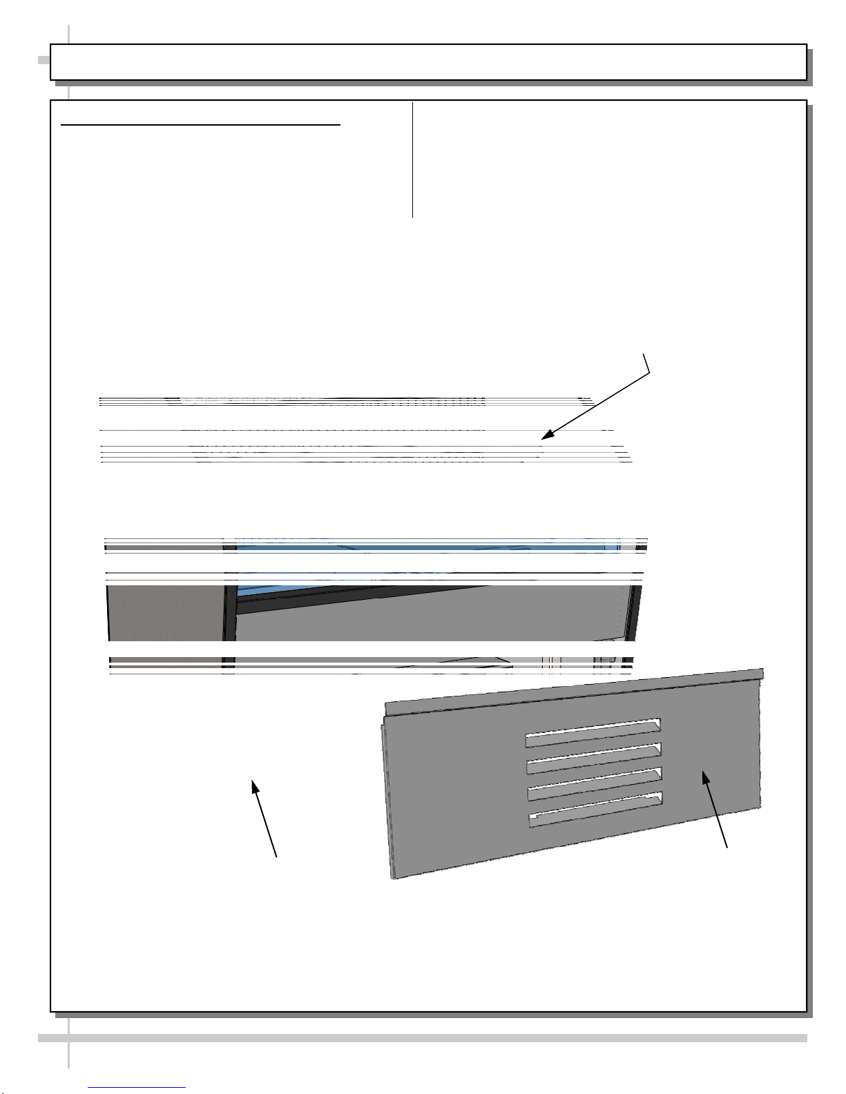
CAUTION! ADVERSE CONDITIONS / SPACING ISSUES
Performance issues caused by adverse conditions are NOT warranted.
End panels must be tightly joined or kept at least 6-inches away from
any structure to prevent condensation.
Unit must be kept at least 15-feet from exterior doors, overhead HVAC
vents or any air curtain disruption to maintain proper temperatures.
Unit must not be exposed to direct sunlight or any heat source
(ovens, fryers, etc.).
Tile floors, low ceilings or small rooms increase noise level. Whisper
Cool compressor blankets or remote units resolve noise level issues.
Keep at least 8-inch clearance above unit for air discharge
(self-contained units only).
CAUTION
CAUTION! LAMP REPLACEMENT GUIDELINES
LED lamps reflect specific size, shape and overall design.
Any replacements must meet factory specifications.
Fluorescent lamps have been treated to resist breakage and
must be replaced with similarly treated lamps.
CAUTION
PRECAUTIONS
This sheet contains important precautions to prevent
damage to unit or merchandise.
Please read carefully!
See previous page for specifics on OVERVIEW,
TYPE, COMPLIANCE and WARNINGS.
WIRING DIAGRAM
Each case has its own wiring diagram folded and in its
own packet.
Wiring diagram placement may vary; it may be placed
near ballast box, field wiring box, raceway cover, or
other related location.
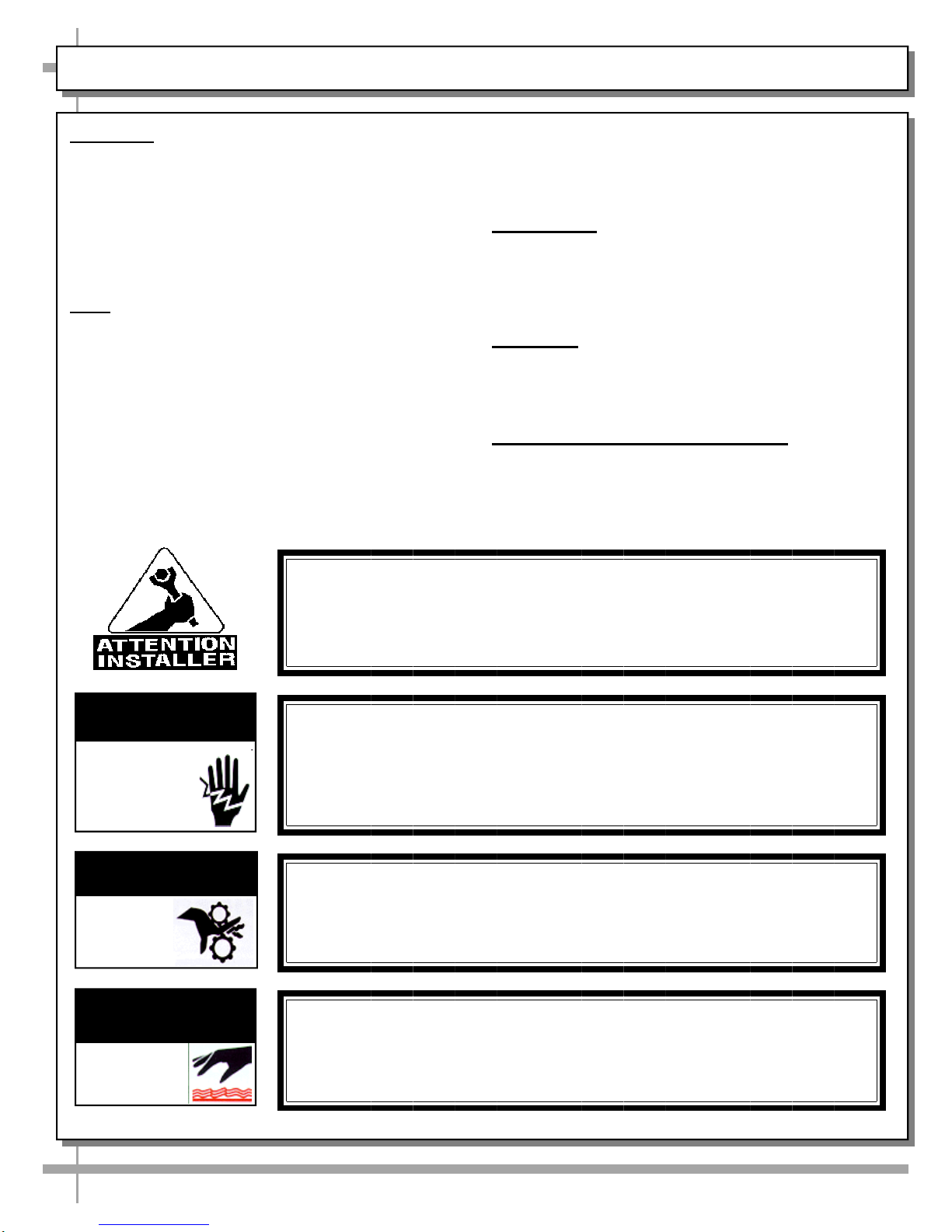
CAUTION! POWER CORD AND PLUG MAINTENANCE
Risk of electric shock. If cord or plug becomes damaged,
replace only with cord and plug of same type.
CAUTION! GFCI BREAKER USE REQUIREMENT
If N.E.C. (National Electric Code) or your local code
requires GFCI (Ground Fault Circuit Interrupter) protection,
you MUST use a GFCI breaker in lieu of a GFCI receptacle.
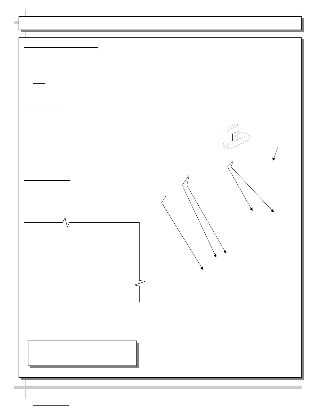
CAUTION! CHECK CONDENSATE PAN
Water on flooring can cause extensive damage!
Before powering up unit, check and confirm that:
Condensate pan is DIRECTLY UNDER condensate drain.
Overflow pan has plug connected to its box. Units with
optional Clean Sweep™ MUST HAVE 2 plugs connected.

5
SHIPMENT CONDITION / DAMAGE DISCOVERED DURING DELIVERY or UNCRATING / SHORTAGES
1.Shipment Condition
Before and during unloading check all equipment for damage.
2.Damage Discovered During Delivery
3rd Party Carrier:Describe damage on freight bill and obtain
signature of driver. Carrier will supply necessary claim forms.
If these steps are not taken, carrier may refuse your claim.
Prepaid and Add:Contact carrier (and follow same procedure as
with 3rd party carrier). Also contact Structural Concepts at
1-800-433-9489.
3.Damage Discovered After Uncrating
3rd Party Carrier:Contact carrier within 10 days of delivery for
their procures; retain all packaging. If these steps are not taken,
carrier may refuse your claim.
Prepaid and Add:Contact carrier (and follow same procedure as
with 3rd party carrier). Also contact Structural Concepts at
1-800-433-9489 within 10 days of delivery.
4.Shortages
If a shortage exists (and it is the responsibility of Structural
Concepts) call 1-800-433-9489. Structural Concepts will
acknowledge shortages within 10 days from receipt of
equipment.
If a shortage involves the carrier, notify carrier immediately and
request an inspection.

6
CASE REMOVAL FROM SKID [LEVELERS OR CASTERS]
2. Remove Case (With Casters) From Skid
A. Place ramp up against skid (to allow case to
smoothly slide off from skid).
B. Maintain support of case at all times or center
of gravity may cause case to fall.
C. Unlock Casters. Slide unit to rear of skid.
Slide down ramp and off from skid.
Ramp
Various Types Of
Case Shipping
Brackets
1. Removing Case Shipping Brackets That Are Attached To Skid
Remove screws holding Case Shipping Brackets to skid.
Remove Case Shipping Brackets from Skid.
See illustrations below. Note: Shipping Brackets will vary in size, shape, material and location
depending upon case type and model.
Support case
while sliding
down ramp.

INSTALLATION
7
1. Ventilation and Clearance
It is recommended that Self-Contained refrigerated
cases maintain a airflow clearance of approximately
6” at the rear to 12” in the front of the case.
Obstruction or restriction of air can void warranty.
6”
Front
Grille
2. Removing Shipping Screws
Plastic glides are mounted to the unit base to assist
in sliding the condenser out for access.
Remove the front grill by removing the screws
located in each of the corners.
Remove the shipping screws located at base of
condenser frame.
Shipping Screws
12”
Front of Case
Top View Side View

START-UP AND OPERATION
8
1. Merchandiser Start-Up - Main Power
Turn on main power switch located behind the
front grille. Main power switch is on left hand
side of base. Replace front grille.
>> Supply power will start evaporator coil fans,
and the compressor motor.
From front of case, raise deck pans and check to see
that the coil fan is functioning properly.
Replace front grille by inserting screws in locations
provided.
Main Power
Switch
Removable
Front Panel
Optional Shelf [Not
on All Cases]

START-UP AND OPERATION, CONTINUED
2. Merchandiser Start-Up/Lights
Turn on the main power. Remove the front grille
by removing the screws located in each of the
corners. Switch is on the left hand side of base.
Supply power will start evaporator coil fans, and
the compressor motor. From the front of the
case, raise the deck pans and check to see that
the coil fans are all functioning properly.
Replace front grille by inserting screws in
locations provided.
Turn on the lights. Light switch is in the interior
of the case. Switch may be above or below the
top shelf and to the left or right side [as shown in
illustration below]. First time lighting may require
a short warm-up period for the bulb. Slightly dim
or a flickering of new bulb is normal. If light do
not turn on, see TROUBLESHOOTING
[TO BE PERFORMED BY STORE
PERSONNEL] section in this operating
manual.
9
3. Temperature Settings
The case temperature is set at the factory, (supply
air 25 °F for a case temp of 41 °F), as determined
by the case size.
The temperature is controlled by a thermostat. If
a temperature setting change is required, refer to
temperature control access.
4. Product Rotation
To prevent freezing or spoilage of stock, product
must be rotated.
At every re-stocking, rotate old stock to front of
shelves and new stock to rear of shelves.
Light Switch Location [at
Either Left or Right Side
of Rear Plenum]
Optional Shelf [Not
on All Cases]

10
MAINTENANCE
Refrigerant lines are flexible to facilitate
maintenance. However, use caution to avoid
crimping or kinking copper tubing while
sliding condenser unit out from under case!
Plastic glides are mounted to the unit base to
assist in sliding the condenser out for access.
Remove shipping retaining screws.
Slide condenser unit forward approximately
twelve inches to access the light ballast.
Ballast is located on the left side of the
condenser in electrical box. See illustration
below left.
1. Shelf Assembly Removal
Shelf can be removed for cleaning or adjustment.
For lighted shelving, unplug the light cord.
Lift shelf straight up to separate from brackets.
Remove brackets.
Note: Initially, it may be necessary to remove the
nylon shipping bracket retainer. Pliers will be
required to accomplish this task.
2. Light Fixtures
Light fixture is located on the top header of case.
Removal of lamp:
Rotate lamp (1/4-turn) so that pins are aligned in
slots and remove bulb.
Installation of lamp:
Align pins with slot.
Insert pins into socket and rotate 1/4 turn to
secure pin contacts in socket.
3. Ballast Access
Assembly or disassembly and servicing
to be accomplished by licensed electrical
contractors only.
Remove the front grille by lifting up and off.
Evaporator
Fan
Deck Pans
Bracket Retainers
Top Header
Caution! Do not crimp or kink
copper tubing while sliding
condenser unit out from under case!
View of Ballasts (After Removal
of Electrical Box Cover)

11
MAINTENANCE, CONTINUED: HONEYCOMB AIR DIFFUSERS
Preventive maintenance should be performed
every 30 days unless conditions warrant a more
frequent replacement cycle.
Honeycomb Air Diffuser Removal
Honeycomb is located in discharge air duct.
A. Wedge a non-metallic device of suitable strength (such
as a ballpoint pen) between the honeycomb and the end
panel.
Caution! Use care not to dislodge the heating wire (that
prevents condensation on the lamp assembly).
B. Apply pressure to collapse the honeycomb to allow it to
be pulled out of honeycomb retainer.
C. Pry downward and away from honeycomb retainer.
Clean honeycomb with warm water and soap solution.
Submerse if necessary.
Use brush to dislodge stubborn or sticky residue.
Dry by using vacuum’s blow mode (vs. suction mode).
Honeycomb Air Diffuser Installation
D. Squeeze honeycomb to allow it to fit into honeycomb
retainer.
E. Carefully slide honeycomb into place.
F. Adjust honeycomb so that it fits flat against retainer.
It must not be wavy or out of position.
Note: For honeycomb air diffusers in other locations,
these same general instructions apply.
A
B
C
D
E
F
Note: Model features and options may vary.
Honeycomb
Air Diffuser

12
REFRIGERATION FUNDAMENTALS - PAGE 1 of 2
Temperature Control Access
Assembly or disassembly and servicing to be
accomplished by licensed electrical /
refrigeration contractor.
Temperature control module is located to the left
side of the condenser package. See below.
Follow the Carel® Temperature Controller
section of this manual for specifics on adjusting
temperature settings.
Refrigeration: Access, Connections & Servicing
Assembly or disassembly and servicing is to
be accomplished by licensed refrigeration
contractors only.
Plastic Glide
Servicing refrigerant is accomplished from the
rear of the case.
Note: Condenser unit does not slide to the rear.
Lift front panel up and off hooks to remove.
Service connections are located to the left of the
compressor.
>> See next page for illustrated parts breakdown
of condenser unit.
Plastic Glide
Light Ballasts Shown
After Electrical Box
Cover Is Removed Temperature
Control Module
Caution! Do not crimp or kink
copper tubing while sliding
condenser unit out from under case!
Optional Shelf [Not
on All Cases]

13
REFRIGERATION FUNDAMENTALS - PAGE 2 of 2
Hot Gas Condensate Unit
Assembly or disassembly and servicing must
be accomplished by licensed electrical /
refrigeration contractor.
Remove the front grille by lifting up and off.
Plastic glides are mounted to the unit base to
assist in sliding the condenser out for access.
Ensure that shipping screws have been removed.
Hot Gas
Serpentine Coil
Wicking Material
[Optional]
Compressor
and
Electrical Box
Overflow Evap. Pan
[Electric Coil] and
Electrical Box
Sight Glass
Filter Dryer
Condensate
Pan
Caution! Though refrigerant lines are flexible
to facilitate front access maintenance, do not
crimp or kink copper tubing while sliding
condenser unit out from under case!
Slide condenser unit forward approximately 12”
to access components.
Wicking material [optional] may be part of hot gas
loop serpentine coil.
After servicing or cleaning unit, carefully slide
condensing unit back under case.
Return front grille to case.
Refrigerant
Line Loop
Condenser Motor
And Fan
Refrigerant
Line Loop
Support

14
SERIAL LABEL LOCATION & INFORMATION LISTED / TECHNICAL INFO & SERVICE
Serial Label Location & Information Listed / Technical Information & Service
Serial labels are located near the electrical access on your case.
Serial labels contain electrical, temperature & refrigeration information, as well as regulatory
standards to which the case conforms.
For additional technical information and service, see the TECHNICAL SERVICE page in this
manual for instructions on contacting Structural Concepts’ Technical Service Department.
See images below for samples of both refrigerated and non-refrigerated serial labels.
----- Sample Serial Label For Refrigerated Case -----
----- Sample Serial Label For Non-Refrigerated Case -----
SAMPLE ONLY
SAMPLEONLY
SAMPLE ONLY
SAMPLE ONLY
SAMPLE ONLY
SAMPLE ONLY

15
CLEANING SCHEDULE [TO BE PERFORMED BY STORE PERSONNEL]
AREA FREQUENCY INSTRUCTIONS
Case
Exterior Daily Acrylic:Clean acrylic sneeze guard with a mild soap and water solution and a soft cloth.
Caution! Never use ammonia-based cleaners on acrylic. Incorrect cleaning agents
or abrasive cleaning cloths cause acrylic surfaces to ‘cloud’ over time.
Daily Stainless Steel “Mirrors” on Each Inside End Panel:
Wash with a solution of hand dishwashing liquid detergent and water; or a solution of
baking soda and water. Rinse and polish dry with paper towel or soft cloth.
Never use scouring powders or steel wool. It will scratch stainless steel.
Brighten by polishing with cloth dipped in vinegar or in ammonia; sprinkle baking soda
on sponge and rub gently; rinse. Polish dry with paper towel.
Remove streaks or heat stains by rubbing with club soda.
Daily End Panels, Front Panel, Toe-Kick, etc.: Wipe off all surfaces with warm water and mild
soap solution and non-abrasive cloth.
Weekly Wood, Laminate and Painted Surfaces:Clean with mild soap and water solution and a
soft cloth.
Monthly Under Case:Remove rear panel (and/or front panel). Clean under case with vacuum.
Case
Interior Daily Decks & Inserts:Wipe down and clean with mild soap, water & soft cloth.
Daily Shelves:Shelves can be cleaned with a warm soap and water solution and soft cloth or
paper towel. For stubborn stains or residue, shelves can be removed and cleaned with
soap and water solution or submersed in hot, soapy water solution. Rinse thoroughly.
Dry. Return to case.
Weekly Decks & Inserts:Remove and clean with mild soap, water & soft cloth
Weekly Shelving Brackets / Air Return Grilles / Decking
Wipe off shelving brackets, air return grilles and decking with moist cloth.
Shelving brackets can be removed for more thorough cleaning.
Air return grilles can be removed for more thorough cleaning.
Decking is NOT to be removed by store personnel.
Weekly
Condenser Coil:Vacuum or brush grille condenser coil at case front. Use metal or fiber
brush to remove dust and dirt that can collect on condenser coils. Be careful not to
damage the fins on the coil.

16
CLEANING SCHEDULE [TO BE PERFORMED BY TRAINED SERVICE PROVIDERS ONLY]
Maintenance Freq. Instructions
Case
Exterior Qtly Condensing Coil: Using vacuum with soft-bristled brush or air pressure or an
industrial strength vacuum, clean the dust and dirt that may collect on the
condenser coil. Use the soft-bristled brush to dislodge caked dust and debris that
may form on coil.
Qtly Under Case Cleaning:Once refrigeration package is clear of unit, vacuum under
case to remove all dust and dirt that may collect.
Case Interior Qtly Tub, Coil and Drain:Remove evaporator fan panel and clean tub, coil and drain
with warm water and mild soap solution. Remove any debris that may clog drain.
Qtly Compressor Area:Slide out from case. Wipe off dust & debris w/moist cloth.
Qtly Hot Gas Loop Condensate Unit:Turn off power. Disconnect case from power
source. Remove front panel. Slide out condenser unit. Use a de-scaling solution
(such as CLR® that will prevent corrosion, lime and rust) to thoroughly clean
condensate pan and overflow electric coil condensate pan. Use wet /dry vacuum
to remove all residue. Use clean towel dipped in soap and water solution to wipe
down all fans, motor, refrigeration lines, cords, knobs, sight glass, connectors and
all other surfaces. Wipe dry. Slide back under case. Replace front panel.
Qtly Evaporative Wicking Material [Optional]:Wicking material (if any on your hot gas
loop condensate system) may be dirty or worn and need replacement.
Slide refrigeration system out from under unit.
After refrigeration system has been carefully slid out from under unit, replace
wicking material with new. If wicking material is not available, contact Structural
Concepts®. See toll-free number at last page of this operating manual.
Qtly Fan Blades, Shroud, Drain: Wipe down each blade and shroud with moist cloth.
Clean out drain. See images #6 and 7 below.
Qtly Honeycomb:See PREVENTIVE MAINTENANCE - HONEYCOMB AIR
DIFFUSERS [SERVICE TECHNICIANS ONLY] section in this manual for specs.
Qtly Upper and Lower Step Inserts:Remove from Case. Clean w/soap and water.
WARNING! TURN OFF POWER TO CASE BEFORE PERFORMING PREVENTIVE MAINTENANCE!
Warning:
Condensate
pan may be
hot. Allow
pan to cool
30-minutes
before
cleaning.

17
PREVENTIVE MAINTENANCE [TO BE PERFORMED BY TRAINED SERVICE PROVIDERS] - Page 1 of 2
PREVENTIVE
MAINTENANCE FREQUENCY INSTRUCTIONS
Case Exterior Monthly Condensing Coil:
Remove front panel.
Use vacuum with soft-bristled brush; clean dust and dirt that
may collect on the condenser coil. See illustration below.
Caution! Coil fins are sharp. Handle with care!
Replace rear grille to case (4 screws).
See illustration below.
Quarterly Clean Sweep™ Condensing Coil (Optional):Disconnect power
from case before cleaning Clean Sweep™Condenser Coil!
Remove Rear Grille (by removing 4 screws).
Slide/Roll out condensing unit assembly.
Remove the four (4) screws holding the Clean Sweep™ rails
intact.
Remove the Clean Sweep™rail.
Wash rails’ brushes in hot water and mild soap solution.
If brushes are worn, they must be replaced. Call Technical
Service Department to replace. Toll-Free number is listed at
end of manual.
Clean Condensing Coil: Use air pressure or industrial strength
vacuum; clean the dust and dirt that may collect on the
Condenser Coil.
Caution! Coil fins are sharp. Handle with care!
Reattach Clean Sweep rail to condensing unit (4 screws).
Slide/Roll Condensing Unit Assembly back under case.
Replace Rear Grille to case (4 screws).
See photos below.
(4) Screws
--- Above photos are taken after rear grille has been removed from case ---
Condensing
Coil
Brushes
Rail

18
PREVENTIVE MAINTENANCE [TO BE PERFORMED BY TRAINED SERVICE PROVIDERS] - Page 2 of 2
WARNING! TURN OFF CASE BEFORE PERFORMING PREVENTIVE MAINTENANCE!
PREVENTIVE
MAINTENANCE FREQUENCY INSTRUCTIONS
Case Exterior Quarterly Compressor Area: Disconnect power from case before cleaning
Condenser Coil!
Slide/Roll out from under case.
Use moist cloth to wipe off dust & debris that collects on various
parts.
Quarterly Condensate Pan:Disconnect from receptacle box. Remove
mounting screw(s) from base. Use a de-scaling solution (such as
CLR® that will prevent corrosion, lime and rust) to clean pan.
Rinse thoroughly; do not submerse in water.
Quarterly Under Case Cleaning:Once refrigeration package is clear of unit,
vacuum under case to remove all dust and dirt that may collect under
case.
Case Interior Quarterly Tub, Coil, Drain, Fan Blades, Motors, Brackets:
Disconnect power from the case before cleaning the Tub, Coil, Fan,
Motor and Drain Area!
Remove Decking, Sub-Deck and Fan Shroud.
Use vacuum to clean Evaporator Coils.
Clean Tub, Coil and Drain with warm water, clean cloth, brush
and mild soap solution.
Remove any debris that may clog drain.
Clean Fan Blades, Motors and Brackets by wiping down with
moist cloth.
Quarterly Honeycomb Air Diffuser:Remove the honeycomb. See
MAINTENANCE, CONTINUED: HONEYCOMB AIR DIFFUSERS
section in this manual for step-by-step instructions.

19
TROUBLESHOOTING [TO BE PERFORMED BY STORE PERSONNEL] - PAGE 1 of 2
Product is Drying Out Check the relative humidity in the store.
Water on the Floor Caution! Water on flooring can cause much damage! Until cause is
determined (and unit repaired), follow these procedures:
Use wet-dry vacuum (or mop & bucket) to remove standing water.
Use ‘catch pans’ for water to drain into. Swap out regularly until case has
completely drained.
Check store conditions.
To prevent condensation in Type 1 environments, maximum conditions are
to be 55% humidity / 75° Fahrenheit.
For Type 2 environments, maximum conditions are to be 60% humidity /
80° Fahrenheit.
See serial label (at case rear near main power switch) for Type of case.
If unable to resolve issue of water on floor, contact technical service. Call
toll-free number listed at end of manual.
Excessive Fan Noise Check that the case is aligned, level and plumb.
System is not Operating Check that the utility power is on.
Check that the MAIN power switch is on.
Check the circuit breaker box for tripped circuits.
Digital Control Display
is Blank Check that the MAIN power switch is on.
Check the circuit breaker box for tripped circuits.
Fans Not Working Check that the MAIN power switch is on.
Check that the case is aligned, level and plumb.
Case Lights Not
Working Check that light is properly installation.
Check bulb for proper connection.
Check for burned out bulb.
Clean dirt and dust from the bulb to prevent flickering.
Check that light switch is in the on position.

20
TROUBLESHOOTING [TO BE PERFORMED BY STORE PERSONNEL] - PAGE 2 of 2
See OVERVIEW / TYPE / COMPLIANCE / WARNINGS /
PRECAUTIONS / PLUGS / WIRING section in this manual for
issues pertaining to case location. Wide temperature fluctuation
can take place in certain environments.
Not Holding Temperature If a large amount of warm product was added to the case, it will take
time for the temperature to adjust. Unit needs pre-chilled product.
The temperature will change during defrost cycle but will return to
normal when compressor turns on.
Check to see if the condenser coil has been cleaned.
Check that the case is not in the sun or near a heat or
air-conditioning vent.
Check air grilles for obstruction and remove.
Ensure that front air grilles are not obstructed by product or other
décor.
Note: Product displayed on Front Air Grilles will cause case to
run warm and will negate warranty.
Condensing Unit Not Operating Check that the main power switch is turned on.
Check that case is on and the control display is not blank. If blank,
call toll-free number at end of manual.
Controller may be in defrost mode. Compressor cycling on and off is
a normal condition. Carel® Temperature Controller Section in this
manual.
Not Holding Temperature Check that the coil fans are working.
Check that the discharge air is not disrupted or blocked by product.
If a large amount of warm product was added to the case, it will take
time for the temperature to adjust.
Check the coil for ice build up.
Check that the condenser coil is clean.
Check that the case is not in the sun or near a heat or air
conditioning vent.
Case temperature will rise during defrost mode but will return to
normal. Proper product temperature will be maintained.
This manual suits for next models
1
Table of contents