Obsolete DP-10 User manual

Operating Instructions
Betriebsanleitung
Mode d'emploi
Manual de Instrucciones
GB
D
F
E
Differential Pressure Transmitter, Model DP-10
Differenzdruck-Messumformer, Typ DP-10
Transmetteur de pression différentielle, Type DP-10
Transmisor de presión diferencial, Modelo DP-10
Differential Pressure Transmitter, Model DP-10

GB
D
F
E
2
2333401 07/2009 GB/D/F/E
Operating Instructions Model DP-10 Page 3 - 11
Betriebsanleitung Typ DP-10 Seite 12 - 21
Mode d'emploi Type DP-10 Page 22 - 31
Manual de Instrucciones Modelo DP-10 Página 32 - 41
Information
This symbol provides you with information, notes and tips.
Warning!
This Symbol warns you against actions that can cause injury to
people or damage to the instrument.

WIKA Operating Instructions Differential Pressure Transmitter 3
GB
2333401 07/2009 GB/D/F/E
Contents
1. Safety instructions 4
2. Measuring principle 4
3. Mounting 5
3.1 Mounting instructions 5
3.2 Process connections 5
4. Dimensions in mm 6
5. Electrical connection 6
6. Calibration instructions 8
6.1 Zero point adjustment (Z) 8
6.2 Span adjustment (S) 8
6.3 Adjustment of the alarm contacts 8
7. Specifications 10
8. EC-Declaration of Conformity 42
Contents

4
GB
WIKA Operating Instructions Differential Pressure Transmitter
2333401 07/2009 GB/D/F/E
1. Safety instructions / 2. Measuring principle
1. Safety instructions
The relevant national safety provisions (e.g. VDE 0100) must be
observed when mounting, putting into commission and operat-
ing this pressure transmitter. Severe injuries and/or damage
might occur as a result of non-compliance with the correspond-
ing provisions. Only qualified personnel is authorised to work on
these instruments.
Please observe the following operating parameters
The pressure transmitter is exclusively suitable for dry, clean,
non-aggressive gases.
Do not blow into the process connections!
The measuring cell might be damaged by the respiratory
pressure.
Max. medium/ambient temperature: 10 ... 50 °C
It has to be made sure that during transportation both
process connections are open. Instruments with absolute
pressure measuring ranges must be transported in pressure
compensation cabins.
2. Measuring principle
The pressure mesurement is realised via a sensitive diaphragm or, in the case of
absolute pressure measuring ranges, a capsule which is adapted to the measuring
range. An inductive system generates a linear signal which changes in proportion to
the prevailing pressure.

WIKA Operating Instructions Differential Pressure Transmitter 5
GB
2333401 07/2009 GB/D/F/E
3. Mounting
3. Mounting
The differential pressure transmitter is designed for wall-mounting. After unscrewing
the two screws at the case the black connection socket can be pulled off the case.
The socket has rated break points for the fastening screws.
3.1 Mounting instructions
The wall-mounting should be carried out in a vertical position, i.e. the process
connections facing down, because the instrument was adjusted in this position.
Thus a possible condensate penetration into the pressure line is avoided.
The mounting location should be free of shocks, vibrations and heat irradiation.
The instrument should not be mounted in the close environment of sources of
interference (e.g. transformers, motors, senders).
3.2 Process connections
2 x hose connection 6.6 x 11 mm
for hoses with an inside diameter of 5 ... 6 mm.
Pressure is to be connected to the „+“ connection.
Vacuum is to be connected to the „-“ connection.
Instruments with absolute pressure measuring ranges have only
one process connection.

6
GB
WIKA Operating Instructions Differential Pressure Transmitter
2333401 07/2009 GB/D/F/E
4. Dimensions in mm / 5. Electrical connection
4. Dimensions in mm
Digital display
5. Electrical connection
The cable is led through the M12 x 1.5 gland into the connection socket. In the
socket are screw terminals for the wiring (terminal area up to 1.5 mm²).
SW 10
M12 x 1.5
Power supply
Sink e.g. display

WIKA Operating Instructions Differential Pressure Transmitter 7
GB
2333401 07/2009 GB/D/F/E
5. Electrical connection
2-wire
3-wire
4-wire (AC-Supply)
Be cautious when connecting supply voltages.
Do not connect supply voltage to the output terminals
L1
N

8
GB
WIKA Operating Instructions Differential Pressure Transmitter
2333401 07/2009 GB/D/F/E
6. Calibration instructions
Please start the calibration only after a running-in period of approx.
30 - 60 minutes.
6.1 Zero point adjustment (Z)
For the zero point adjustment both process connections must be open. After pulling
off the rubber plugs at the instrument‘s front the output signal can be adjusted with
the zero potentiometer (Z).
For the adjustment of pressure transmitters with absolute pressure measuring range
the process connection is to be connected to a pressure generator and an absolute
pressure reference via a T-piece. Subsequently an absolute pressure is generated for
which the output signal shall be: 0 V / 0 mA or 4 mA. Now the output signal can be
adjusted with the zero potentiometer (Z).
6.2 Span adjustment (S)
For the span adjustment the nominal pressure must be connected via a T-piece from
the pressure generation to the pressure reference and the pressure channel.
The WIKA precision calibrator model CPC2000, which has a pressure generation
and a pressure reference, is excellently suitable for this task.
Pressure is to be connected to the “+” connection and vacuum to the “-” connec-
tion. Now the output signal may be adjusted with the span potentiometer (S).
6.3 Adjustment of the alarm contacts
For the adjustment of the alarm contacts the reference pressure must be applied
at which the contact is supposed to close. This is accomplished with a pressure
generator which is connected to the pressure reference and the pressure channel via
a T-piece. Pressure is to be connected to the “+” connection and vacuum to the “-”
connection. The potentiometer of the switch point SP I or II must be adjusted until
the red LED above the respective potentiometer lights up, i.e. the switch value has
been reached and the contact closes.

WIKA Operating Instructions Differential Pressure Transmitter 9
GB
2333401 07/2009 GB/D/F/E
6. Calibration instructions
Then the pressure at which the contact is desired to break again must be applied.
Now the respective hysteresis potentiometer must be adjusted ( ) until the LED
goes out again. The switching hysteresis is adjustable within a range of 0 ... 15 %.
1. Potentiometer for
switching hysteresis
2. Potentiometer for
switching points
3. LCD (optional)
4. Signal
5. Power Supply
6. Product No.
7. Alarm contacts
(optional)
8. Span potentiometer
9. Zero potentiometer
10.Process connection
CE

10
GB
WIKA Operating Instructions Differential Pressure Transmitter
2333401 07/2009 GB/D/F/E
7. Specifications
Specifications Model DP-10
Pressure ranges1) mbar 0.6 1 1.6 2.5 4 6 10 16 25
Over pressure safety mbar 3 5 8 12.5 20 30 50 80 125
Pressure ranges1) mbar 40 60 100 160 250 400 600 1000
Over pressure safety mbar 200 300 500 800 1000 1000 1200 2000
Maximum static pressure mbar 1000 {2000}
Pressure reference
relative pressure, differential pressure, {absolute pressure2) from
500 mbar abs; special pressure range 800 ... 1200 mbar abs}
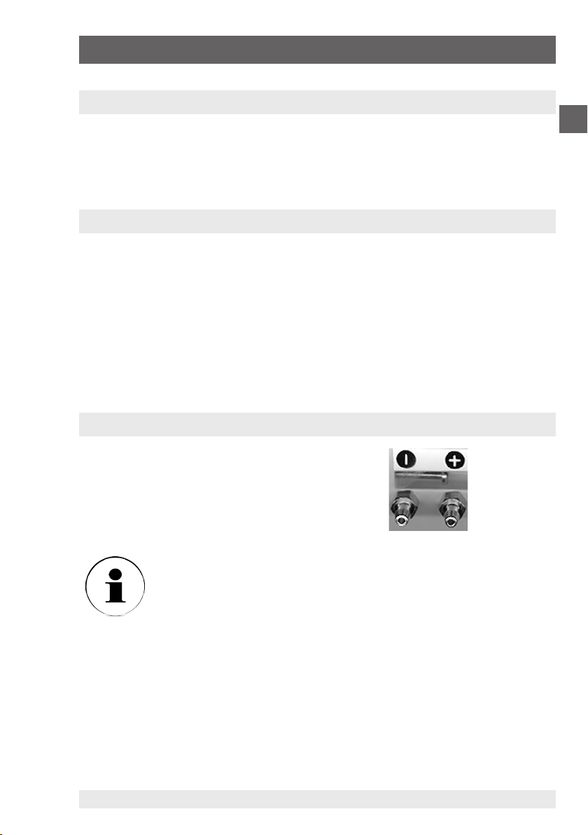
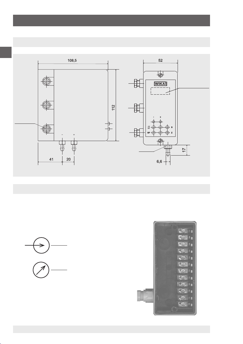
Pressure connection mm two hose connections Ø 6.6 x 11 for hoses with
inside Ø 5 ... 6 {2 x clamping ring connection G ⅛, Ms}
Materials
Wetted partsMs, CuBe, PU, Ni
Casebottom part: ABS, glass fibre reinforced, top part: ABS
Power supply UBDC V
19 ... 31 {12 ... 30 with signal output 4 ... 20 mA, 2-wire system}
AC V {24, 115 or 230 (respectively ± 10 %, 50 ... 60 Hz)}
Signal output and Maximum load RA0 ... 10 V, 3-wire system RA> 2,0 kOhm
{0 ... 5 V, 3-wire system} RA≤2,0 kOhm
{0 (4)... 20 mA, 3-wire system} RA≤500 Ohm
{4 ... 20 mA, 2-wire system} RA≤(UB[V] – 12 V) / 0,02 mA
{other on request}
Power consumption mA ≤ 10; (3-/4-wire); (AC-/DC-supply)
Response time (10 ... 90 %) ms approx. 20 {attenuation on request}
Adjustability zero point / span ± 5 % of span
Accuracy ≤ 1.0 % of span (limit point calibration) {0.5 or 0.2 for pressure
range from 2.5 mbar}
Hysteresis ≤0.1 % d. Spanne
Repeatability ≤0.05 % of span
1-year stability ≤0.5 % of span (at reference conditions)
Permissible temperature of
Medium-10 ... +50 °C 14 ... 122 °F
Ambient-10 ... +50 °C {-10 ... +60 °C} 14 ... 122 °F (14 ... 140 °F)
Storage-10 ... +70 °C 14 ... 158 °F
Compensated temperature range +10 ... +50 °C 14 ... 122 °F
Temperature coefficients in compensated temp range:
Mean TC of zero≤0.3 % of span/10K
Mean TC of range≤0.3 % of span/10K
{ } Items in curved brackets are optional extras for additional price.
1) The measuring ranges 0 ... 0.1 mbar; 0 ... 0.25 mbar; 0 ... 0.4 mbar are available on request.
For these measuring ranges a larger measuring cell and consequently also a case with larger dimensions is required.
2) Only with 4 ... 20 mA 2-wire, other output signals on request.
7. Specifications

WIKA Operating Instructions Differential Pressure Transmitter 11
GB
2333401 07/2009 GB/D/F/E
7. Specifications
Specifications Model DP-10
Shock resistance g 10
Suitable media clean, non-aggressive, dry gases
Sensor volume ml approx. 5 (approx. 7 for measuring ranges < 2.5 mbar)
Increase in volume ml approx. 1 at nominal pressure
CE-conformity Interference emission and immunity see EN 61 326 / A1;
declaration of conformity on request european guideline for
low voltages EN 610 10
{integrated indicator}
DigitalLC display, 3 ½-digits; height of digits 10 mm, pick-up rate
3/sec.
Analogueanalogue indicator 0 ... 100 %
{Alarm contacts} only with 3-wire systems
Number1 or 2
Switching functionstandard setting 2 x max.
Adjustability1 ... 100 % of span
Switching accuracy≤1 % of span
Switching repeatability0,2 % of span, typical
Switching hysteresis0 ... 10 % of span, adjustable
Contacts1 potential-free relay change-over contact per alarm contact
Contact ratingAC 6 A, 230 V with ohmic load
{Root-evolved output signal}
Accuracy1,0 % of span
Calculationthe root is evolved according to the following equations:
UR= √ 10 x UL) UL= linear output 0 ... 10 V
IR = √ 20 x IL) IL= linear output 0 ... 20 mA
Electrical connection via cable gland PG 7 and internal screw terminals in the
bottom part of the case, terminal champing diameter 1.5 mm²
Ingress of protection IP54, per EN 60 529 / IEC 529
Weight kg approx. 0.6 {approx. 0.7 with power supply}
Dimensions mm see drawings
Mounting case for wall mounting
{ } Items in curved brackets are optional extras for additional price.
1) The measuring ranges 0 ... 0.1 mbar; 0 ... 0.25 mbar; 0 ... 0.4 mbar are available on request.
For these measuring ranges a larger measuring cell and consequently also a case with larger dimensions is required.
2) Only with 4 ... 20 mA 2-wire, other output signals on request.

2333401 07/2009 GB/D/F/E
WIKA Betriebsanleitung Differenzdruckmessumformer12
D
Information
Dieses Zeichen gibt Ihnen Informationen, Hinweise oder Tipps.
Warnung!
Dieses Symbol warnt Sie vor Handlungen, die Schäden an
Personen oder am Gerät verursachen können.

2333401 07/2009 GB/D/F/E
WIKA Betriebsanleitung Differenzdruckmessumformer 13
D
Inhalt
1. Sicherheitshinweise 14
2. Messprinzip 14
3. Montage 15
3.1 Montagehinweise 15
3.2 Prozessanschlüsse 15
4. Abmessungen in mm 16
5. Elektrischer Anschluss 16
6. Kalibrieranleitung 18
6.1 Einstellung des Nullpunktes (Z) 18
6.2 Einstellung der Spanne (S) 18
6.3 Einstellung der Grenzkontakte 18
7. Technische Daten 20
8. EG-Konformitätserklärung 42
Inhalt

2333401 07/2009 GB/D/F/E
WIKA Betriebsanleitung Differenzdruckmessumformer14
D
1. Sicherheitshinweise / 2. Messprinzip
1. Sicherheitshinweise
Beachten Sie unbedingt bei Montage, Inbetriebnahme und
Betrieb dieses Druckmessumformers die entsprechenden natio-
nalen Sicherheitsvorschriften
(z. B.: VDE 0100). Bei Nichtbeachten entsprechender
Vorschriften können schwere Körperverletzungen und/oder
Sachschäden auftreten.
Nur entsprechend qualifiziertes Personal darf an diesen Geräten
arbeiten.
Bitte beachten Sie folgende Betriebsparameter
Der Druckmessumformer ist ausschließlich für trockene,
saubere, nicht aggressive Gase geeignet.
Nicht in die Prozessanschlüsse blasen!
Die Messzelle kann durch den Lungendruck beschädigt
werden.
Max. Messstoff-/Umgebungstemperatur: 10 ... 50 °C
Beim Transport ist darauf zu achten, dass beide Prozessan-
schlüsse offen sind. Geräte mit Absolutdruck-Messbereichen
müssen bei Luftfracht in Kabinen mit Druckausgleich beför-
dert werden.
2. Messprinzip
Die Druckmessung erfolgt über eine dem Messbereich angepasste, empfindliche
Plattenfeder, bzw. einer Kapselfeder bei Absolutdruck-Messbereichen. Ein induk-
tives System erzeugt ein lineares Signal, das sich proportional zum anstehenden
Druck verändert.

2333401 07/2009 GB/D/F/E
WIKA Betriebsanleitung Differenzdruckmessumformer 15
D
3. Montage
3. Montage
Der Differenzdruck-Messumformer ist für Wandmontage vorgesehen. Nach dem
Lösen der beiden Schrauben am Gehäuse kann der schwarze Anschluss-Sockel
vom Gehäuse abgezogen werden. Im Sockel sind Sollbruchstellen für die Befesti-
gungsschrauben vorhanden.
3.1 Montagehinweise
Der Wandanbau sollte in vertikaler Lage erfolgen, d. H. die Prozessanschlüsse
zeigen nach unten, da das Gerät in dieser Lage eingestellt wurde. Das eventuelle
Eindringen von Kondensat in die Druckleitungen wird so vermieden.
Der Montageort sollte frei von Erschütterungen, Vibrationen, sowie von Wärme-
einstrahlung sein.
Die Montage sollte nicht in unmittelbarer Nähe von Störquellen (z. B. Trafos,
Motoren, Sender) erfolgen.
3.2 Prozessanschlüsse
2 x Schlauchanschluss 6,6 x 11 mm
für Schläuche mit Innendurchmesser 5 ... 6 mm.
Ein positiver Überdruck wird an den „+” Eingang angeschlossen.
Ein negativer Überdruck wird an den „-“ Eingang angeschlossen.
Geräte mit Absolutdruck-Messbereichen verfügen nur über einen
Prozessanschluss.

2333401 07/2009 GB/D/F/E
WIKA Betriebsanleitung Differenzdruckmessumformer16
D
4. Abmessungen in mm / 5. Elektrischer Anschluss
4. Abmessungen in mm
Anzeigefeld
Digitalanzeige
5. Elektrischer Anschluss
Das Kabel wird durch die M12 x 1,5 Verschraubung in den Anschlusssockel geführt.
Im Sockel befinden sich Schraubklemmen für die Verdrahtung (Klemmbereich bis
1,5 mm²).
SW 10
M12 x 1,5
Hilfsenergie
Verbraucher
z. B. Anzeige

2333401 07/2009 GB/D/F/E
WIKA Betriebsanleitung Differenzdruckmessumformer 17
D
5. Elektrischer Anschluss
2-Leiter
3-Leiter
4-Leiter (AC-Versorgung)
Vorsicht beim Anschließen von Versorgungsspannungen.
Versorgungsspannung nicht an die Ausgangsklemmen anschlie-
ßen.
L1
N

2333401 07/2009 GB/D/F/E
WIKA Betriebsanleitung Differenzdruckmessumformer18
D
6. Kalibrieranleitung
Bitte beginnen Sie mit der Kalibrierung erst nach einer Einlaufzeit
von ca. 30 ... 60 Minuten.
6.1 Einstellung des Nullpunktes (Z)
Zum Abgleich des Nullpunktes müssen beide Druckeingänge offen sein. Nach dem
Abziehen der Gummistopfen auf der Gerätevorderseite kann das Ausgangssignal mit
dem Nullpunktpotentiometer (Z) eingestellt werden.
Beim Abgleich von Druckmessumformern mit Absolutdruck-Messbereich wird der
Druckeingang über ein T-Stück mit einer Druckerzeugung und mit einer Absolut-
druckreferenz verbunden. Danach wird der Absolutdruck erzeugt, bei dem das
Ausgangssignal: 0 V bzw. 0 mA oder 4 mA betragen soll. Jetzt kann das Ausgangs-
signal mit dem Nullpunktpotentiometer (Z) eingestellt werden.
6.2 Einstellung der Spanne (S)
Zum Abgleich der Spanne wird der Nenndruck über ein T-Stück von der Druckerzeu-
gung an die Druckreferenz und den Druckkanal angeschlossen.
Der WIKA Präzisionskalibrator Typ CPC2000, der über eine Druckerzeugung, sowie
über die Druckreferenz verfügt, ist hierfür hervorragend geeignet.
Positiver Überdruck wird an den „+“ Eingang und negativer Überdruck an den „–“
Eingang angeschlossen. Nun kann das Ausgangssignal mit dem Spanne-Potentio-
meter (S) eingestellt werden.
6.3 Einstellung der Grenzkontakte
Zur Einstellung der Grenzkontakte wird der Druck angelegt, bei dem der Kontakt
schließen soll. Dies erfolgt mit einer Druckerzeugung, die über ein T-Stück mit der
Druckreferenz und dem Druckkanal verbunden ist. Positiver Überdruck wird an
den „+“ Eingang und negativer Überdruck an den „–“ Eingang angeschlossen. Das
Potentiometer des Schaltpunktes SP I bzw. II wird solange verstellt, bis die rote LED
oberhalb des jeweiligen Potentiometers aufleuchtet. Damit ist der Einschaltwert
erreicht, das Relais ist geschlossen.

2333401 07/2009 GB/D/F/E
WIKA Betriebsanleitung Differenzdruckmessumformer 19
D
6. Kalibrieranleitung
Danach wird der Druck angelegt, bei dem sich der Kontakt wieder öffnen soll. Jetzt
wird das entsprechende Hysterese- Potentiomer ( ) solange verstellt, bis die LED
wieder erlischt. Die Schalthysterese ist im Bereich von 0 ... 15 % einstellbar.
1. Potentiometer für
Schalthysterese
2. Potentiometer für
Schaltpunkte
3. LCD-Anzeige (Option)
4.Signal
5.Hilfsenergie
6.Fabrik-Nr.
7.
Grenzkontakte (Option)
8. Spanne-Potentiometer
9.Nullpunkt-Potentio-
meter
10.Prozessanschluss
CE

2333401 07/2009 GB/D/F/E
WIKA Betriebsanleitung Differenzdruckmessumformer20
D
7. Technische Daten
Technische Daten Typ DP-10
Messbereich1) mbar 0,6 1 1,6 2,5 4 6 10 16 25
Überlastgrenze mbar 3 5 8 12,5 20 30 50 80 125
Messbereich1) mbar 40 60 100 160 250 400 600 1000
Überlastgrenze mbar 200 300 500 800 1000 1000 1200 2000
Maximaler statischer Druck mbar 1000 {2000}
Druckart Relativdruck, Differenzdruck {Absolutdruck2) ab 500 mbar
abs; Sondermessbereich 800 ... 1200 mbar abs}
Druckanschluss mm zwei Schlauchanschlüsse Ø 6,6 x 11 für Schläuche mit Innen-
Ø 5 ... 6 {2 x Klemmringverschraubung G ⅛, Ms}
Werkstoff
Messstoffberührte TeileMs, CuBe, PU, Ni
GehäuseUnterteil: ABS, glasfaserverstärkt, Oberteil: ABS
Hilfsenergie UBDC V 19 ... 31 {12 ... 30 bei Ausgang 4 ... 20 mA, Zweileiter}
AC V {24, 115 oder 230 (jeweils ± 10 %, 50 ... 60 Hz)}
Ausgangssignal und zulässige max.
Bürde RA
0 ... 10 V, Dreileiter RA> 2,0 kOhm
{0 ... 5 V, Dreileiter} RA≤2,0 kOhm
{0 (4)... 20 mA, Dreileiter} RA≤500 Ohm
{4 ... 20 mA, Zweileiter} RA≤(UB[V] – 12 V) / 0,02 mA
{andere auf Anfrage}
Stromaufnahme mA ≤10; (3-/4-Leiter); (AC-/DC-Versorgung)
Einstellzeit (10 ... 90 %) ms ca. 20 {Dämpfung auf Anfrage}
Einstellbarkeit: Nullpunkt/Spanne ± 5 % d. Spanne
Kennlinienabweichung √ 1,0 % d. Spanne (Grenzpunkteinstellung) {0,5 oder 0,2 ab
Messbereich 2,5 mbar}
Hysterese ≤0,1 % d. Spanne
Reproduzierbarkeit ≤0,05 % d. Spanne
Stabilität pro Jahr ≤0,5 % d. Spanne (bei Referenzbedingungen)
Zulässige Temperaturen
Messstoff-10 ... +50 °C 14 ... 122 °F
Umgebung-10 ... +50 °C {-10 ... +60 °C} 14 ... 122 °F (14 ... 140 °F)
Lagerung-10 ... +70 °C 14 ... 158 °F
Kompensierter Temperaturbereich +10 ... +50 °C 14 ... 122 °F
Temperaturkoeffizienten im Kompensierten Temperaturbereich:
Mittlerer TK des Nullpunktes≤0,3 % d. Spanne/10K
Mittlerer TK der Spanne≤0,3 % d. Spanne/10K
{ } Angaben in geschweiften Klammern beschreiben gegen Mehrpreis lieferbare Sonderheiten
1) Die Messbereiche 0 ... 0,1 mbar; 0 ... 0,25 mbar; 0 ... 0,4 mbar sind auf Anfrage lieferbar.
Bei diesen Messbereichen wird eine größere Messzelle und deshalb ein Gehäuse mit größeren Abmessungen benötigt.
2) Nur bei 4 ... 20 mA Zweileiter, andere Ausgangssignale auf Anfrage.
7. Technische Daten
Table of contents
Languages: