Ocean MS 4F I User manual

OVEN
SERVICE MANUAL
Model
MS 4F I
Specifications are subject to possible modifications without prior notice.
Les présentes spécifications sont susceptibles d'être modifiées sans préavis.
Las especificaciones estàn sujetas a cambios sin previo aviso
Pictures are only sketches which may be different from your equipment.
Les images sont seulement de croquis qui peuvent être différentes du design de votre équipement.
Las imágenes son sólo los bosquejos que pueden ser diferentes de su equipo.

Ovens Service Manual 60cm – 75cm - 90cm -
90X48cm (EU)
Last U date 09 Se 2019
This document has been published to be used for service only.
The contents are subject to change without notice
CONTENTS
1. SERVICING REQUIREMENTS
1.1 HEALTH & AFETY
1.1.1 Electrical afety
1.1.2 Good Working Practices
1.1.3 Insulation Test
1.1.4 heet Metal Edges
4. TROUBLE SHOOTING GUIDE
4.1 --
4.2 OVEN NOT OPERATIVE
4.3 COOLING FAN PROBLEM
4.4 CONVECTION FAN PROBLEM
4.5 --
4.6 OVEN LIGHT PROBLEM
4.7 --
4.8 DI PLAY PROBLEM
4.9 DOOR HINGE PROBLEM
4.10 BAD COOKING PERFORMANCE
7. COMPONENT REPLACEMENT AND ADJUSTMENT PROCEDURE
7.1 OVEN REMOVAL
7.2 COOLING FAN MOTOR UB TITUTION
7.3 OVEN DOOR REMOVAL
7.4 CONVECTION FAN MOTOR UB TITUTION
7.5 RING ELEMENT UB TITUTION
7.6 UPPER ELEMENT UB TITUTION
7.7 LOWER ELEMENT UB TITUTION
7.8 --
7.9 --
7.10 DOOR GA KET UB TITUTION
7.11 COOKING AFETY OR COOLING FAN THERMO TAT UB TITUTION
7.12 PIT MOTOR UB TITUTION (IF PRE ENT)
7.13 MECHANICAL OR ELECTRONIC THERMO TAT UB TITUTION
7.14 TEMPERATURE PROBE UB TITUTION
7.15 DOOR EXTERNAL GLA AND HINGE UB TITUTION
7.15b DOOR EXTERNAL GLA AND HINGE UB TITUTION (PANORAMIC DOOR)
7.16 WITCH OF FUNCTION UB TITUTION (IF PRE ENT)
7.17 ELECTOR OF FUNCTION UB TITUTION
7.18 WITCH OF FUNCTION UB TITUTION (60CM 75CM – 90CM)
7.18b WITCH OF FUNCTION UB TITUTION (90X48CM)
1 di 30

7.19 ELECTRONIC TIMER UB TITUTION
7.20 TERMINAL BLOCK UB TITUTION
2 di 30
Servicing Requirements
1.1
Health & Sa ety
Note: When servicing the oven, health and safety issues must e considered at all times. Specific safety issues
are listed elow with their appropriate icon. These are illustrated throughout the service information to remind
service people of the health and safety issues
1.1.1 Electrical Sa ety
WARNING! TO AVOID ELECTRIC SHOCK!
Do not attem t to service this oven without suitable training and
qualifications.
Ensure the main power has een disconnected efore servicing any part of the oven. If
the power is required to e on for electrical fault finding, then extreme care should e
taken not to make contact with electrical components other than with testing pro es.
Ensure the oven is turned off when removing any electrical component or connection.
1.1.2 Good Working Practices
Ensure the work areas are kept tidy and free of hazards while servicing the
oven. On completion of the servicing, ensure the oven and work areas are
left clean and tidy.
1.1.4 Insulation Test
Megger test to check insulation.
1.1.5 Sheet Metal Edges
When working around cut sheet metal edges use appropriate gloves or
protection to eliminate the chance of receiving a laceration.
3 di 30
Trou leshooting guide
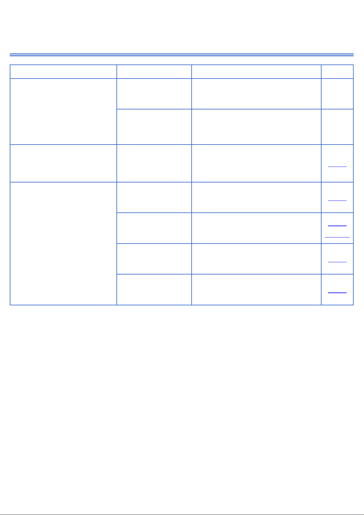
4.2
Oven not operative
Anomaly Possible Cause Corrective Action section
Oven does not run
No power supplies.
Main reaker or main
fuses
Replace the fuses
--
Short circuit Find the short circuit and remove it.
Check internal connections (short
circuit, interruptions, etc.) --
Oven does not run
Power supply ok.
Display OFF
Connections to the
Electronic Timer
Check the connection or replace the
Electronic Timer 7.19
The Display is ON ut the oven
doesn’t heat.
The temperature
limiting (tripped)
Check if the cooling fan system works
properly and in case replace the
safety thermostat 7.11
Connections to the
function switch
Check the connection or replace the
Switch 7.18
7.18b
The working
thermostat
Check if the thermostat is properly
connected and in case replace the
working thermostat 7.13
Relay on the
Electronic timer
Check the connection or replace the
Electronic Timer 7.19
4 di 30

Trou leshooting guide
4.3
Cooling Fan Problems
Anomaly Possible Cause Corrective Action section
Fan does not run
No power supplies
Bad connection
Selector roken.
Check the connectors and the
harness.
Replace switch selector 7.17
Cooling Fan
thermostat roken.
(contact opened)
Replace the cooling fan thermostat
7.11
Fan does not run
Power supply ok.
Blocked rotor Replace fan 7.2
Burned coil Replace fan 7.2
Noisy fan Lose attachment
screws on cooling
assem ly
Check attachment screws on cooling
assem ly or replace fan 7.2
5 di 30

Trou leshooting guide
4.4
Convection Fan Problems
Anomaly Possible Cause Corrective Action section
Fan does not run
No power supply
Bad connection
Mode selector not
switching
Check the connectors and the harness
Replace switch selector 7.17
Fan does Not run
Power supply ok.
Blocked rotor Replace fan 7.4
Burned coil Replace fan 7.4
Noisy fan Lose attachment
screws on assem ly
Check attachment screws
Check nut on working fan for tightness
or replace it --
6 di 30
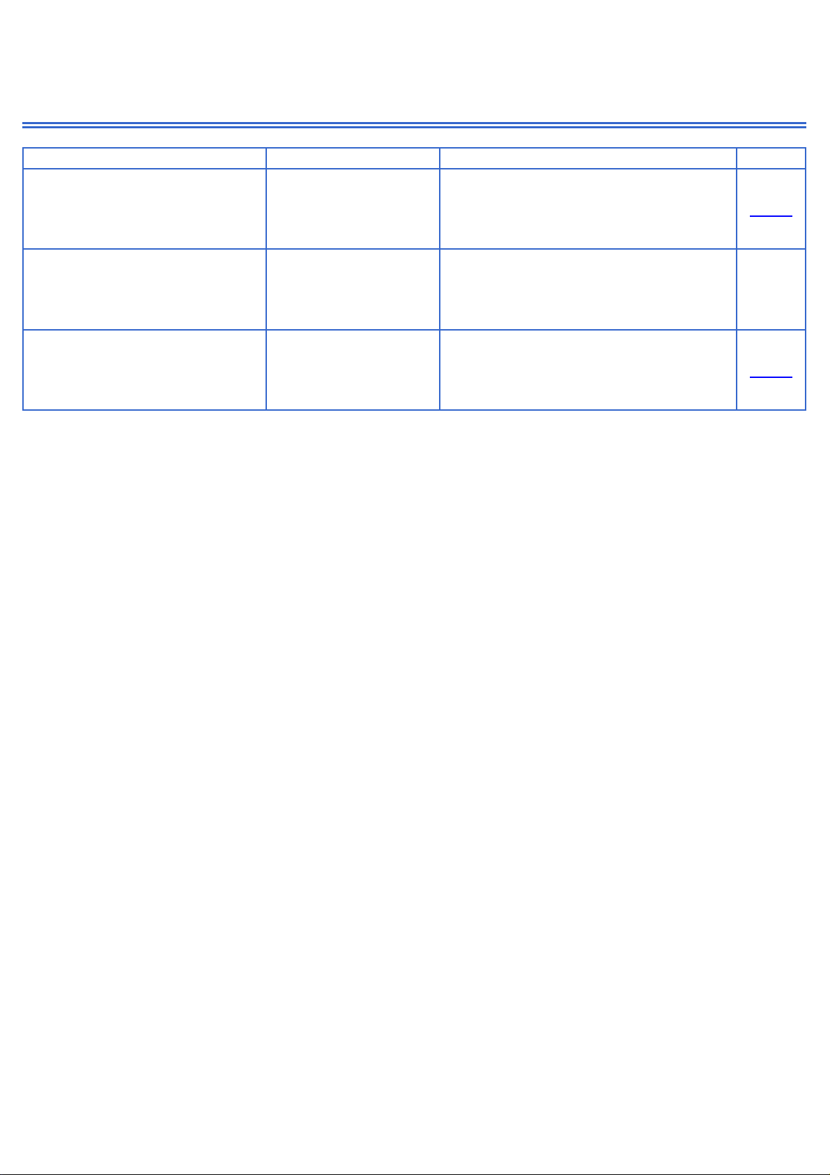
Trou leshooting guide
4.6
Oven Light Problems
Anomaly Possible Cause Corrective Action section
The Oven lights are always
OFF.
No power supply.
Bad connection
Selector roken.
Check the connectors and the
harness.
Replace the switch selector 7.17
The Oven lights are always
OFF.
Power supply is ok.
Lamps are urned
out.
Replace lamps. See
User
manual
The Oven lights are always
ON.
Bad connection
Selector contact is
roken or in short
circuit.
Check the connectors and the
harness.
Replace the switch selector 7.17
7 di 30

Trou leshooting guide
4.8
Display Problems
Anomaly Possible Cause Corrective Action section
The timer display does not
function
The power supply is
not working.
Check and eventually replace the
Electronic Timer. 7.19
8 di 30

Trou leshooting guide
4.9
Door Hinge Problems
Anomaly Possible Cause Corrective Action section
The door does not close or
there is not sealing etween
door and gasket
Hinges system is
roken or damaged
Replace the units 7.15
7.15b
9 di 30
Table of contents


