DCC-SC01HD32 Rev.900-717-30-00
-4
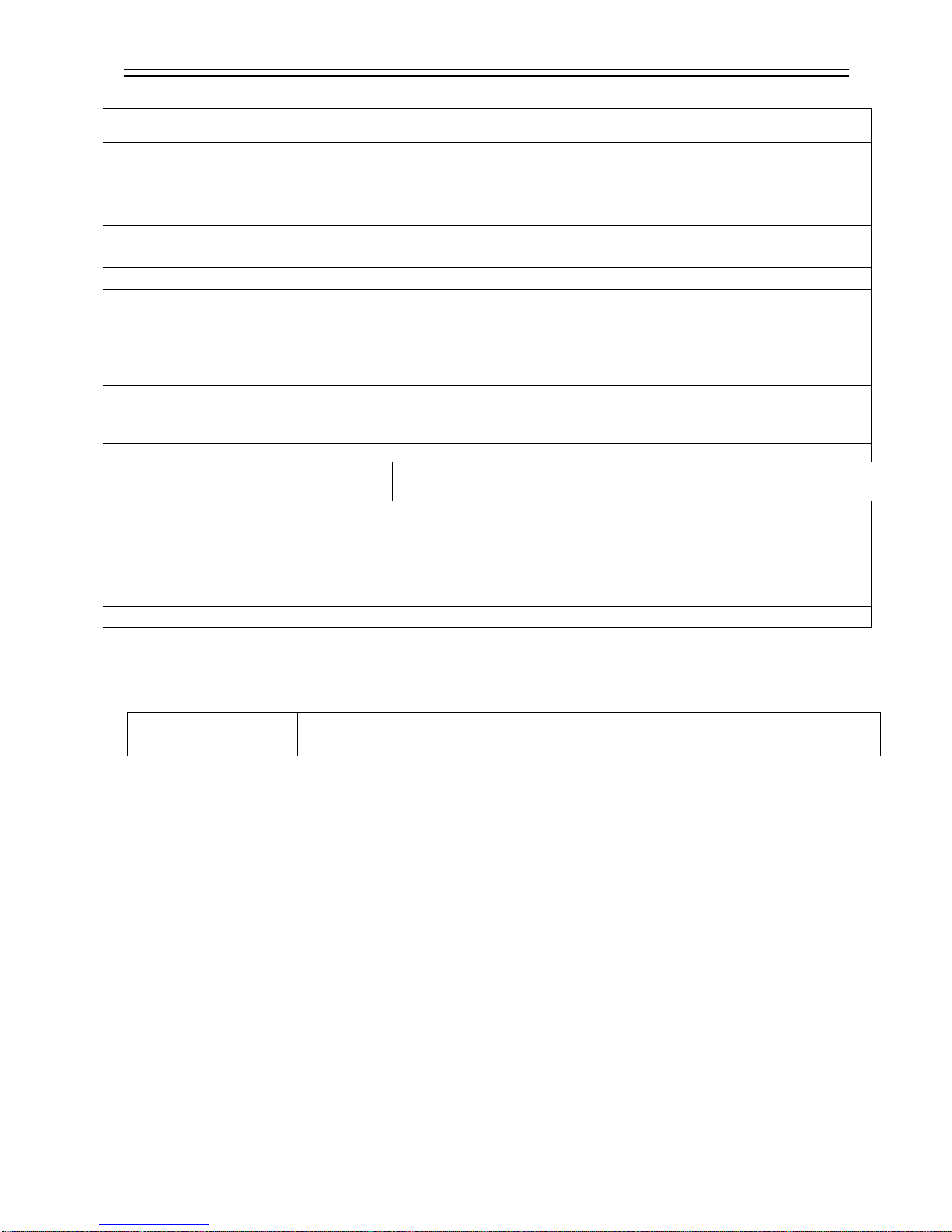
5. Specifications
5.1. General Specifications
(1) Pick up device
Device Type 1/3 type CMOS SONY IMX035LQR-C
Effective Pixel Numbers 1329(H) × 1049(V)
Unit Cell Size 3.63μm(H) ×3.63μm(V)
Chip Size 7.64mm(H) × 7.64mm(V)
(2) Resolutions 1280(H) × 720(V)
(3) Aspect Ratio 16 : 9
(4) Video output
frequency
60fps Horizontal Frequency 45 kHz
Vertical Frequency 60 Hz
59.94fps Horizontal Frequency 44.95 kHz
Vertical Frequency 59.94 Hz
50fps Horizontal Frequency 37.50 kHz
Vertical Frequency 50 Hz
(5) Sync. system Internal sync
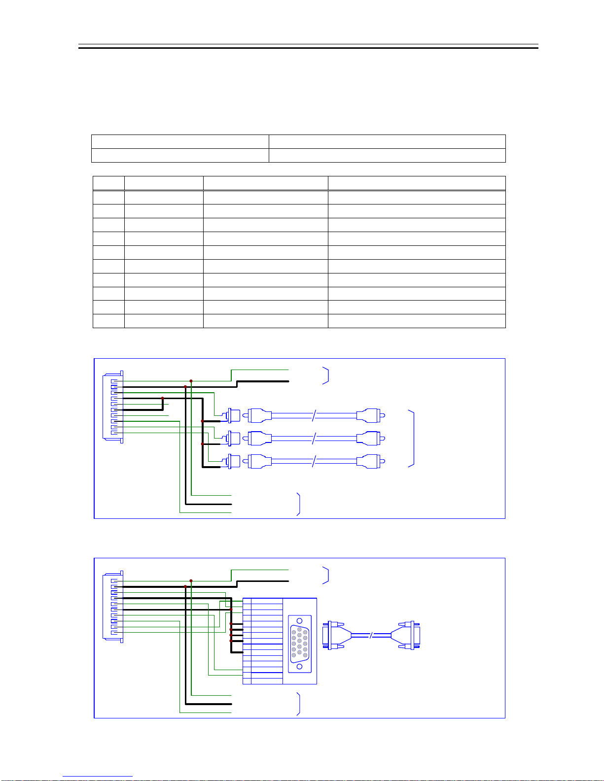
(6) Video output standard Analog Component Output : Y/Pb/Pr 1Vp-p (3 Values, Sync signals) 75Ωterminal
RGB Output : RGB 1Vp-p (without SYNC ) 75Ωterminal
HD, VD TTL level (over 2.1V 1kΩterminal)
(7) Horizontal resolution 600TV lines (contour correction SHARP)
(8) Sensitivity F4.0 2000lx
(9) Minimum illumination 60fps,59.94fps : F2.5 6.0lx (with dedicated board camera lens)
F1.4 3.0lx (with F1.4 lens)
50fps : F2.5 5.0lx (with dedicated board camera lens)
F1.4 2.5lx (with F1.4 lens)
Conditions : VIDEO 50%, AGC 36dB, Electrical Shutter OFF
(10) Dust or stains
in optical systems No dust or stain shall be detected on the testingscreen with dedicated lens
installed, or with setting the camera aperture at F16 if there is no lens.
(11) Power requirements DC+9~+15V
(12) Power consumption 2.0W (Max. 2.4 W) at DC+12V IN
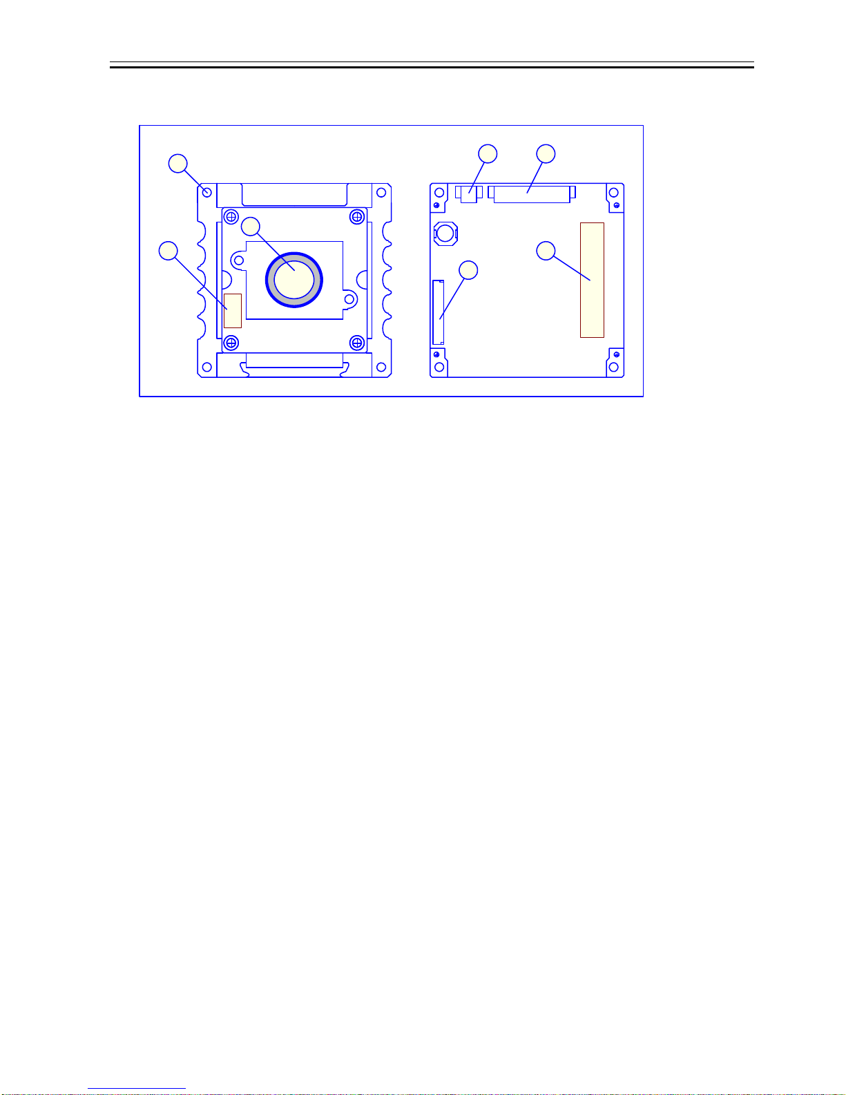
(13) Dimension Refer to overall dimension drawing.
(14) Mass Approx. 45g (including optional dedicated lens).
(15) Lens Mount Dedicated board camera lens mouont. ※Refer to overall dimension drawing.
(16) Gain Setting AGC (Max gain : +18dB, +24dB, +30dB, +36dB), AGC OFF(0dB)
MANUAL : 0dB~36dB
(17) Shutter Speed Variable
Range OFF : 1/60(60fps, 59.94fps),1/50(50fps)
FL : 1/100(60fps, 59.94fps), 1/120(50fps)
MANUAL : 1/10k, 1/4k, 1/2k, 1/1k, 1/500, 1/250, 1/120, 1/100, 1/60, 1/50, 1/30,
1/25, 1/15, 1/8, 1/4, 1/2, 1s, 2s, 4s, 8s
AUTO : 1/10ks~8s (Upper or lower limit can be set.)
(18) White Balance
Adjustment Range ATW1 : 2200~9000K, ATW2 : 3200~6500K
Preset:3200K, 4800K, 6500K, Manual: 2200~9000K
(19) Electrical Zoom ×1~×4 PAN, TILT
(20) AUTO IRIS Signals Responses are adjustable.
Usable with electrical shutter (with priority to electrical shutter).