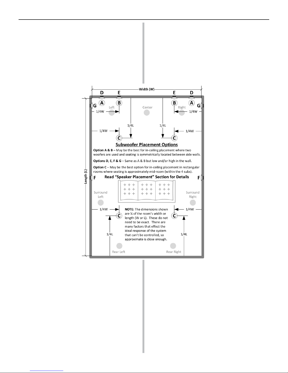
room width from the corners. (Options B, C, & E) This works well when there
are symmetrically parallel walls of similar composition to the left and right
of the subwoofers. The placement of the subwoofers can be in the ceiling
or the walls. Though the subwoofers will be less efcient at transferring
energy to the room at these locations (compared to corners), the bass will
likely be more uniform at different listening positions across the width of the
room. This arrangement is likely the best option when Auto Room Calibration
systems are not employed.
If the listening room is rectangular in shape, then four woofers can be
arranged in a central rectangular pattern in the ceiling. (Option C) Of the
suggested locations, this location is the least efcient at transferring energy
to the room. However, the advantage
is that it can help to provide more
uniformity in the bass reproduction
within the boundaries of the subwoofers.
This option is likely best for mid-room
seating where there are multiple rows
and where Auto Room Calibration
systems are not employed.
Option F is also a consideration because
the woofers are close to the seating
area, but it lacks the advantages of
corner loading and ¼ wavelength
spacing.
A few more notes on placement:
Mirroring the placement of Options A,
B D, E, & G at the back of the room is a
way to increase the system output. It
is also reasonable to place subwoofers
behind furniture. The effect on the
output should be small as long as there
is sufcient space (>1in, 25mm) to allow
the subwoofer to radiate its energy and
the furniture is not so large as to trap the
energy. With that said, a china cabinet is
probably not the best piece of furniture
to place in front of a subwoofer.
Finally, if the application is a modern
home theater, then run the Auto Room
Calibration system on your AV receiver.
See the EQUALIZATION section on
this page.
PASSIVE CONNECTION
These subwoofers should ideally be driven by a dedicated amplier but
they have enough sensitivity (efciency) to be used passively in a “passive
sub-sat” arrangement when a passive crossover is employed. The term
passive means that the subwoofer is connected in parallel with the main
set of listening speakers, (referred to as satellites), hence the term “passive
sub-sat.” In a “passive sub-sat” arrangement two subwoofers are required,
(one for each audio channel). Optimizing a passive sub-sat system requires
greater skill and knowledge than an active system and it is recommended
that a qualied expert be employed for this type of application.
In an active sub-sat system (not passive) the subwoofer is driven by a
separate amplier, independent of the amplier that drives the main satellite
speakers. Home theater receivers almost always utilize an active sub-sat
conguration.
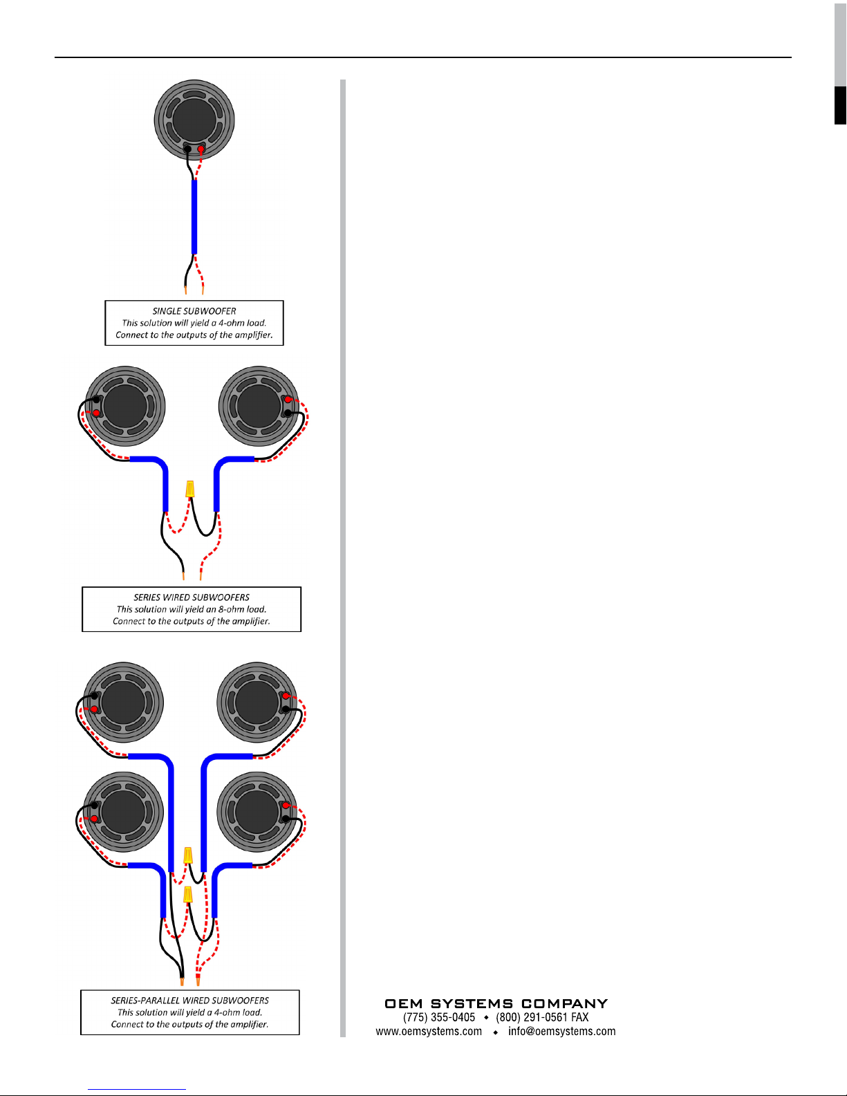
AMPLIFICATION
Depending on the system requirements, the SE-80SWf subwoofer will
perform well with ampliers rated from 50 to 150 Watts RMS at 4 ohms.
(Note: The SE-80SWf is a 4 ohm subwoofer, the power rating of the amplier
should be considered at 4 ohms and not at 8 ohms unless the subs are
connected in series.) Though the subwoofer is rated for 150W, please be
aware that damage can be done by ampliers of even moderate power
if the subwoofer and/or amplier are continuously overdriven for long
periods of time. If you should hear distortion at high listening levels then
the volume should be reduced.
For most installations it is recommended that a dedicated subwoofer
amplier (such as our Model 500) be used to drive the subwoofer(s). The
SE-80SWf subwoofers can also be driven by an ordinary stereo amplier.
However, conventional stereo ampliers almost always lack subsonic
lters* that are incorporated within
dedicated subwoofer ampliers
(like the Model 500). When using a
conventional stereo amplier greater
care must be exercised to ensure
the woofers are not overdriven with
subsonic program material.
*Subsonic lters are used to
reduce the excursion of the woofer
below frequencies which the
woofer can effectively operate and
that would overdrive the woofer at
high listening levels.
Since the SE-80SWf was designed
to operate down to 30Hz, a subsonic
lter should be applied around 35Hz to
ensure the best possible performance
and highest output capability. If your
amplier lacks a subsonic lter then
in many cases a passive lter can be
added at the input. Please contact
us or your dealer for information on
suitable lters.
EQUALIZATION
It is common now for home theater
receivers to include digital signal
processing that performs Automatic
Room Calibration. These systems
perform a number of different
measurements and adjustments,
including equalization. Within a limited
seating area, these can be very effective
at improving the overall system
performance and the quality of the bass. However, not all algorithms work
well and in some cases their success depends of the expertise of the person
setting up the system and their ability to recongure the settings. If you
utilize the Auto Room Calibration system on your receiver and you discover
that it sounds worse afterwards, then we recommend that you restore the
factory default settings and consult an expert to work out the issues.
Note: Equalization can not be used to correct every location in the room
simultaneously. If you optimize the bass for the middle or any other
location in the room then it will not be accurate at many other locations.
That is the nature of the environment.
CROSSOVER
Since this is a subwoofer, it has a limited range of frequencies which it
designed to reproduce. The function of the crossover is to direct the various
frequencies to their proper destinations. Frequencies that are suitable
for the subwoofer are directed to the sub and other higher frequencies
are directed to the main speakers (satellites). If this subwoofer is part of a
SUBWOOFER TIPS & TECHNIQUES