If the holding plate (screw guide 1) height needs to be adjusted, please proceed as directed below.
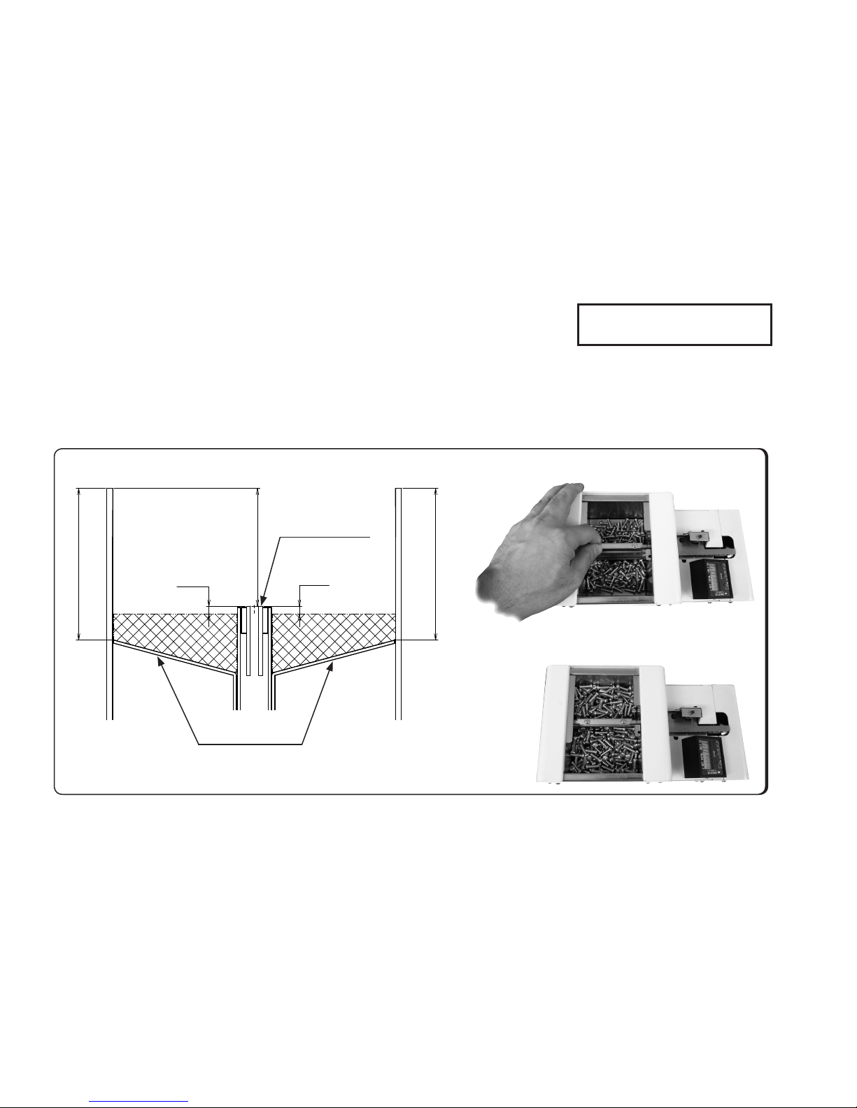
Tilt this machine or operate it so that the screws are delivered to the rail assembly stopper. If there is no clearance between the hold-
ing plate (screw guide 1) and screw heads, the screws cannot move. The screws can move while the shutter is open with an
adequate clearance provided between the holding plate (screw guide 1) and screw heads.
If the screws do not move to the escaper section, loosen the bit guide assembly retaining screw, and rotate the bit guide assembly
up-down adjustment screw counterclockwise with the accessory Allen wrench to move the holding plate (screw guide 1) upward.
Adjust the holding plate (screw guide 1) height by rotating the bit guide assembly height
adjustment screw to provide a clearance of 0 to 1 mm between the holding plate
(screw guide 1) and the head of the screws.
When performing the above adjustment procedure, ensure that the gap between
the holding plate (screw guide 1) and rail is uniform. Please make sure that the gaps
between the holding plate and the rail are the same on the rear end and the front end.
After completion of adjustment, be sure to tighten the bit guide assembly
retaining screw.
If the employed screw has a relatively short shank, ne adjustments are needed.
For screws having a relatively long shank, however, coarse adjustments will sufce.
4-5. Checking and Adjusting the Rail Assembly
- 7-
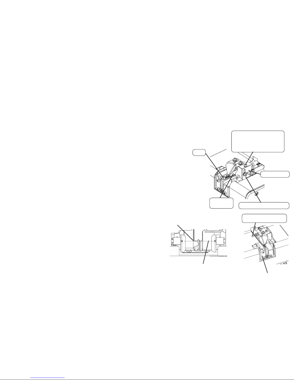
Check the position of the stopper and sensor.
・Ensure that the rail is xed so that "A" portion of the stopper is
0mm to 0.5mm ahead of the sensor optical axis.
・If adjustment is necessary, adjust it front and rear by loosening
the rail front-rear position lock screw
Bit guide assembly
Bit guide assembly retaining screw
Bit guide assembly height
adjustment screw
Clockwise rotation → Descent
Counterclockwise → Ascent
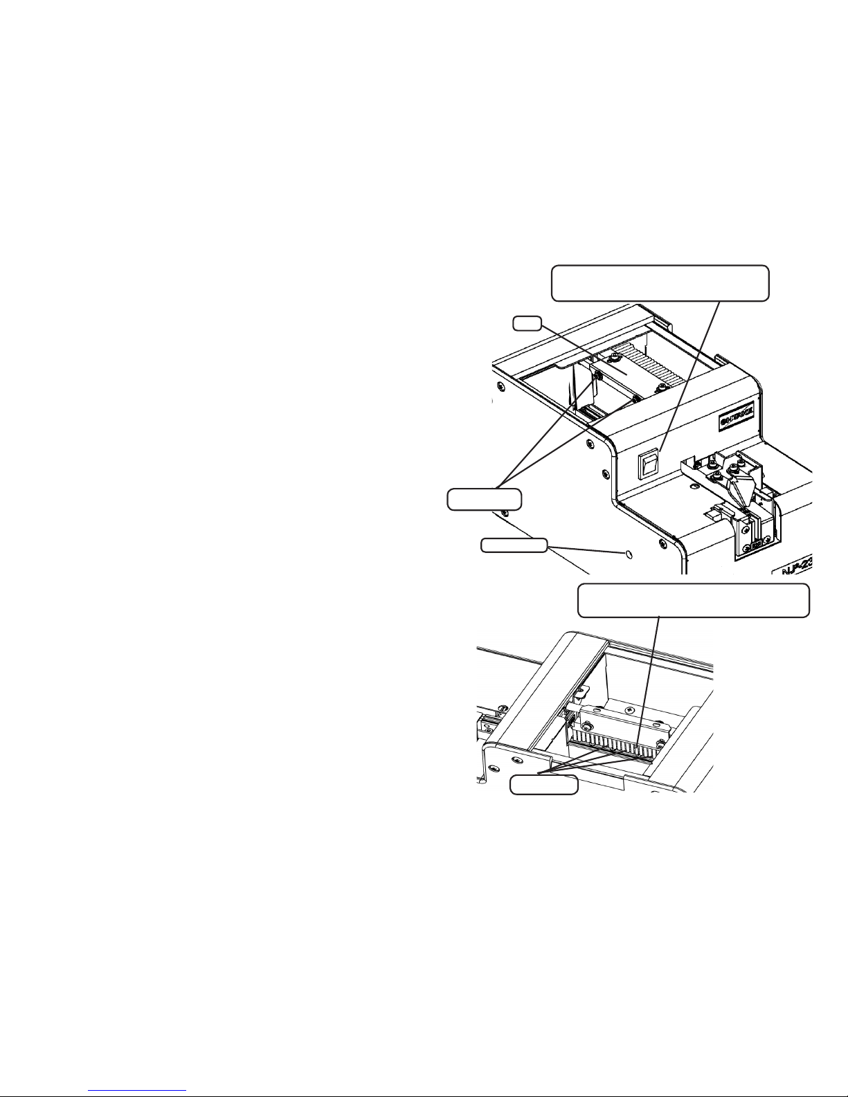
Holding plate
(Screw guide1)
Stopper
Rail front-rear position lock
screw access hole
Rail assembly
A
Sensor optical axis