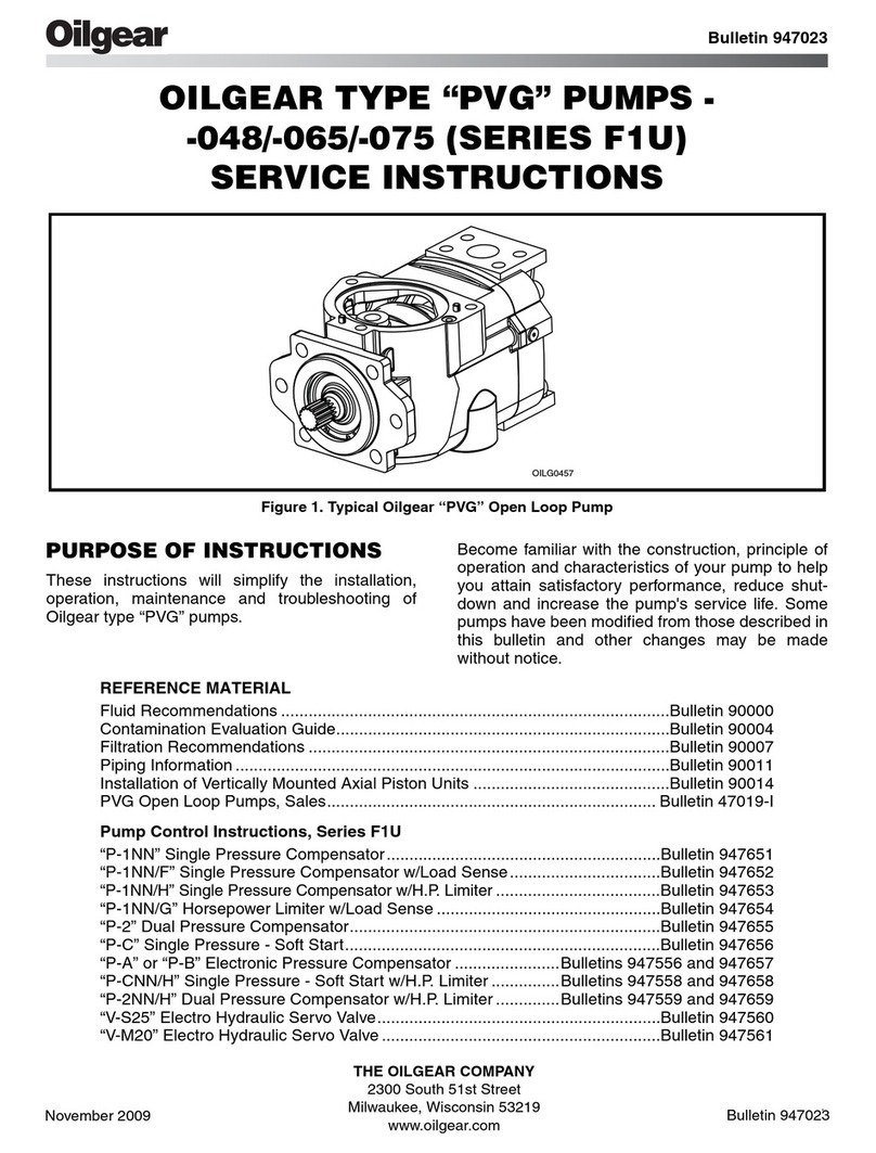
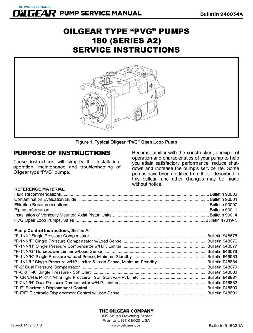
OilGear XD5-100-A1 User manual

Pump Service Manual
XD5-100-A1
Phone: (402) 727-9700
Website: www.Oilgear.com
905 S. Downing Street, Fremont, NE 68025
Page 1 of 31
Issue Date: 1/4/2021
910003
1Purpose of Instructions
These instructions will simplify the installation, operation, maintenance, and troubleshooting of Oilgear’s XD5-100
variable piston pump.
2Reference Material
2.1 General Reference
Description.........................................................................................................................................Bulletin Number
Oilgear Fluid Recommendation ......................................................................................................................... 90000
Oilgear Filtration Recommendation .................................................................................................................. 90007
Oilgear Piping Information................................................................................................................................. 90011
Installation of Vertically Mounted Axial Piston Unit.......................................................................................... 90014
2.2 XD5-100 Documents
Description.........................................................................................................................................Bulletin Number
Installation Bulletin..........................................................................................................................................910001
Figure 1 - Oilgear XD5-100

Pump Service Manual
XD5-100-A1
Phone: (402) 727-9700
Website: www.Oilgear.com
905 S. Downing Street, Fremont, NE 68025
Page 2 of 31
Issue Date: 1/4/2021
910003
3Table of Contents
1 Purpose of Instructions .....................................................................................................................................................................1
2 Reference Material............................................................................................................................................................................1
2.1 General Reference....................................................................................................................................................................1
2.2 XD5-100 Documents.................................................................................................................................................................1
3 Table of Contents ..............................................................................................................................................................................2
4 Safety First.........................................................................................................................................................................................3
4.1 Safety Nomenclature................................................................................................................................................................3
4.2 Warnings ..................................................................................................................................................................................3
5 Pump Characteristics.........................................................................................................................................................................6
5.1 Specifications............................................................................................................................................................................6
5.2 Driveshafts................................................................................................................................................................................6
5.3 Port Sizes ..................................................................................................................................................................................6
5.4 Performance Chart and Inlet Condition ...................................................................................................................................7
6 Control Options.................................................................................................................................................................................8
6.1 Pressure Compensator with Load Sense ..................................................................................................................................8
6.1.1 Pressure Compensator Only, P-1NN................................................................................................................................9
6.1.2 Pressure Compensator and Load Sense, P-1NN/F or P-1NN/B .....................................................................................10
6.1.3 Remote Pressure Compensator, P-RNN ........................................................................................................................12
6.1.4 Remote Pressure Compensator and Load Sense, P-1NN/F ...........................................................................................14
6.1.5 Reconfiguring the Pressure Comp./Load Sense Control................................................................................................15
6.2 Maximum Volume Stop..........................................................................................................................................................16
6.2.1 How to Adjust ................................................................................................................................................................16
7 Installation and Dimensions............................................................................................................................................................17
7.1 Vertical Mounting...................................................................................................................................................................17
7.2 Adjuster and Purge Port Locations.........................................................................................................................................17
7.3 Control Port Locations............................................................................................................................................................17
7.4 Mounting Flange, Lifting Hook, and Rotation Designation ....................................................................................................18
7.5 Driveshafts..............................................................................................................................................................................18
7.6 Case Drain Locations ..............................................................................................................................................................18
7.7 Clearance Dimensions ............................................................................................................................................................19
7.8 Center of Gravity and Dry Weight ..........................................................................................................................................19
7.9 Valve Plate Views ...................................................................................................................................................................20
7.10 Tandem Mount Adapters .......................................................................................................................................................21
8 Troubleshooting ..............................................................................................................................................................................22
9 System Requirements and Installation ...........................................................................................................................................23
10 Replacement Parts......................................................................................................................................................................25
10.1 Pump and Control Seals Kit ....................................................................................................................................................25
10.2 Maximum Volume Stop Kit.....................................................................................................................................................26
10.3 Control Block Kit .....................................................................................................................................................................26
10.4 Exploded Drawings .................................................................................................................................................................27

Pump Service Manual
XD5-100-A1
Phone: (402) 727-9700
Website: www.Oilgear.com
905 S. Downing Street, Fremont, NE 68025
Page 3 of 31
Issue Date: 1/4/2021
910003
4Safety First
Read and understand this entire instruction sheet before repairing or adjusting your Oilgear product. Those who use
and maintain this equipment must be thoroughly trained and familiar with the product. If incorrectly used or
maintained, this product and its equipment can cause severe injury.
4.1 Safety Nomenclature
The following signal words are used in this instruction sheet to identify areas of concern where your safety may be
involved. Carefully read the text and observe any instructions provided to ensure your safety:
THIS SIGNAL WORD INDICATES AN IMMINENTLY
HAZARDOUS SITUATION WHICH, IF NOT AVOIDED, WILL
RESULT IN DEATH OR SERIOUS INJURY.
This signal word indicates a potentially hazardous
situation which, if not avoided, could result in death or
serious injury.
This signal word indicates that a potentially hazardous
situation exists which, if not avoided, may result in
damage to equipment or minor personal injury.
While not directly relevant to the topic
being discussed, the NOTE is used to
emphasize information provided, or
provide additional information which
may be of benefit.
4.2 Warnings
This service information is designed for the
maintenance of your Oilgear product. It contains the
information on the correct procedures determined by
Oilgear for the safe manner of servicing. Always keep
this instruction sheet in a location where it is readily
available for the persons who use and maintain the
product. Additional copies of this instruction sheet are
available through the Oilgear Company. Visit our
website: www.oilgear.com. Please contact us if you
have any questions regarding the information in this
instruction bulletin.
The cleanliness of working on this
pump or the hydraulic system is
extremely important to the safety and
reliability of the pump and the system.
Always make sure the fittings are clean
on the outside before removing them
from their connections, are capped
and plugged when removed and
placed in a clean rag or container until
they are reinstalled.
Some service operations may require special tools or
equipment. If you require information on these items,
please contact Oilgear before attempting these repairs
and service operations.
DO NOT attempt to service this machinery in an
environment where safety regulations are not
established and in place.
DO NOT operate the hydraulic system if a leak is
present. Serious injury may result.

Pump Service Manual
XD5-100-A1
Phone: (402) 727-9700
Website: www.Oilgear.com
905 S. Downing Street, Fremont, NE 68025
Page 4 of 31
Issue Date: 1/4/2021
910003
Hydraulic systems operate under very high pressure.
Hydraulic fluid escaping from a pressurized system can
penetrate unprotected body tissue. DO NOT inspect for
hydraulic leaks with bare hands or other exposed body
parts. As a minimum, wear leather gloves prior to
inspecting for leaks and use cardboard or wood. If leaks
are present, relieve pressure and allow system to cool
prior to servicing. If injured by escaping hydraulic oil,
contact a physician immediately. Serious complications
may arise if not treated immediately. If you have
questions regarding inspecting for hydraulic leaks,
please contact Oilgear prior to servicing.
Hydraulic hoses and tubing must be inspected on a daily
basis for leaks, cuts, abrasions, damage and improper
clearance alongany mounting frame for hidden damage
before the unit is put into service. Replace damaged
hoses or hoses you suspect are damaged before the
system is returned to service! Hoses must be replaced
every two years. Failure to properly inspect and
maintain the system may result in serious injury.
Hydraulic systems are hot. DO NOT TOUCH! Serious
personal injury may result from hot oil. When you have
completed working on the hydraulic system,
thoroughly clean any spilled oil from the equipment.
Do not spill any hydraulic fluids on the ground. Clean
any hydraulic fluids from your skin as soon as you have
completed maintenance and repairs. Dispose of used
oil and system filters as required by law.
DO NOT enter under hydraulic supported equipment
unless they are fully supported or blocked. Failure to
follow this procedure can result in serious injury or
death.
Use correct hoses, fittings, and adapters with the
correct SAE rating when replacing hoses to prevent
possible serious injury. Always replace hoses, fittings,
and adapters with replacements that have a proper,
suitable, working pressure rating. Replacement hoses
must be of the correct length and must comply with the
hose manufacturer’s and Oilgear’s installation
guidelines and recommendations.
Hydraulic hoses have the SAE ratings marked on the
hose to assist you in selecting the correct hose. The
same manufacturer must supply any replacement
hydraulic hoses and fitting assemblies. As an example:
Brand “X” hose and brand “Y” fitting will not normally
be compatible. No “twist” is allowed in the hydraulic
hoses. “Twist” may result in premature hose failure.
This can cause serious injury. Please contact Oilgear for
assistance when required.
Hydraulic cylinders can be holding a function in a
certain position when the pump is OFF. An example of
this is a function being held in the lift or partial lift
position by the cylinders. If a hydraulic line is removed
or the hydraulic circuits or controls are being worked
on, gravity may allow the function being held in
position to drop. All workers and personnel must
remain clear of these areas when working on or
operating the hydraulic system. Block and secure all
devices and functions which apply before beginning
work or operation. Failure to comply with this can
result in serious injury or death.
Any hydraulic pipe which is replaced must conform to
SAE J1065 specifications. If incorrect hydraulic pipe is
installed, the hydraulic system may fail, causing serious
injury. Damaged or leaking fittings, pipes or hoses must
be replaced before the system is returned to service.

Pump Service Manual
XD5-100-A1
Phone: (402) 727-9700
Website: www.Oilgear.com
905 S. Downing Street, Fremont, NE 68025
Page 5 of 31
Issue Date: 1/4/2021
910003
DO NOT heat hydraulic pipe. The carbon content of this
steel tube is such that if heated for bending, and either
water or air quenched, the pipe may lose its ductility
and thereby be subject to failure under high pressure
conditions. Serious injury can result. Damaged or
leaking pipes must be replaced before the system is
returned to service. Please contact Oilgear if you
require assistance or have questions.
All hydraulic pressure must be relieved from the
hydraulic system prior to removing any components
from the system. To relieve the hydraulic pressure from
the hydraulic system, turn off the motor and operate
the control panel with the key in the ON position.
Failure to comply can result in serious injury. If you
have any questions concerning relieving the hydraulic
pressure from the system, please contact Oilgear.
Hydraulic components can be heavy. Use caution while
lifting these components. Serious personal injury can
be avoided with proper handling of the components.
Please contact Oilgear if you require assistance, when
performing hydraulic test procedures, use the proper
hydraulic gauges. Installing an incorrect test gauge
could result in serious injury if the gauge fails. Use
properly rated hydraulic hoses to allow the test gauge
to be read away from moving parts and functions.
Increasing hydraulic pressure beyond the
recommendations may result in serious damage to the
pump and system or serious personal injury and may
void the Oilgear Warranty. If you have questions
concerning hydraulic pressures or testing procedures,
please contact Oilgear before attempting the test
procedures or making adjustments.
An Oilgear pump must not be modified in any way
without authorization from Oilgear. Modifications
may not comply with safety standards, including ANSI
safety standards, and may result in serious personal
injury. Please contact Oilgear if you require assistance.
Any Oilgear pump safety decals must be replaced
anytime they are damaged, missing, or cannot be read
clearly. Failure to have proper decals in place can
result in serious injury or death. (If you require safety
decals, please contact Oilgear for replacement safety
decals, at no charge.)
Be sure everyone is clear of the area around the
hydraulic system before operating after servicing.
Remain attentive at all times when operating to check
your work until you are completely sure it is safe to
return to service. Failure to heed this warning may
result in serious personal injury or death.
Wear the proper protective clothing when operating,
servicing or maintaining the hydraulic system or the
Oilgear pump. Wear the correct protective gear,
safety glasses, gloves, and safety shoes. Serious injury
can result without proper protective gear.
Make sure to keep hands and feet and other parts of
your body clear of revolving or moving parts. Failure
to comply can cause serious injury.
DO NOT wear watches, rings, or jewelry while working
with electrical and mechanical equipment. These items
can be hazardous and can cause serious and painful
injuries if they come into contact with electrical wires,
moving parts, or hydraulic equipment.

Pump Service Manual
XD5-100-A1
Phone: (402) 727-9700
Website: www.Oilgear.com
905 S. Downing Street, Fremont, NE 68025
Page 6 of 31
Issue Date: 1/4/2021
910003
5Pump Characteristics
This section concentrates on the characteristics of the main pump –the components contained by the main housing to
the pump. For information on the control options for the pump, please refer to Section 6.
5.1 Specifications
5.2 Driveshafts
5.3 Port Sizes
CHARACTERISTIC
UNIT
VALUE
Theoretical Max. Displacement
In^3/rev [cc/rev]
6.00 [98.4]
Rated Continuous Pressure
psi [bar]
5,000 [350]
Peak Pressure
psi [bar]
5,800 [400]
Maximum Speed
with a flooded inlet
RPM
2,600
Outlet Flowrate
1,800 RPM, Rated Continuous Pressure
GPM [lpm]
43 [163]
Table 1 - Pump Characteristics
MODEL CODE
DESIGNATION
SHAFT SIZE
ALLOWABLE INPUT TORQUE
K
SAE C Spline
14 Tooth, 12/24 Pitch
7,000 in*lbs. [791 Nm]
S
SAE C-C Spline
17 Tooth, 12/24 Pitch
10,500 in*lbs. [1,186 Nm]
Table 2 - Driveshafts
PORT
SIZE
TORQUE
Inlet
2 Inch SAE, Code 61 Flange
100 ft*lbs [136 Nm]
Outlet
1 Inch SAE, Code 62 Flange
61 ft*lbs [83 Nm]
Case Drain
#12 SAE Port
85 ft*lbs [115 Nm]
Table 3 - Port Table

Pump Service Manual
XD5-100-A1
Phone: (402) 727-9700
Website: www.Oilgear.com
905 S. Downing Street, Fremont, NE 68025
Page 7 of 31
Issue Date: 1/4/2021
910003
5.4 Performance Chart and Inlet Condition
Figure 2 - XD5-100 Performance Chart and Inlet Condition Curve

Pump Service Manual
XD5-100-A1
Phone: (402) 727-9700
Website: www.Oilgear.com
905 S. Downing Street, Fremont, NE 68025
Page 8 of 31
Issue Date: 1/4/2021
910003
6Control Options
XD5’s control mechanism consists of a main control piston mounted in the pump housing, and a module called the
Control Block, mounted to the Valve Plate. This section discusses options and adjustments related to the Control Block.
6.1 Pressure Compensator with Load Sense
XD5’s standard Pressure Comp./Load Sense control can be adapted to run in the following ways:
•Pressure Comp. Only
•Pressure Comp. w/Load Sense
•Remote Pressure Comp.
•Remote Pressure Comp. w/Load Sense
This section describes each option and its adjustments, and provides instructions for reconfiguring an existing XD5 PC/LS
Control to change between these 4 options.
Figure 3 - Control Block, Mounted to the Pump Housing (PC/LS Control Shown)

Pump Service Manual
XD5-100-A1
Phone: (402) 727-9700
Website: www.Oilgear.com
905 S. Downing Street, Fremont, NE 68025
Page 9 of 31
Issue Date: 1/4/2021
910003
6.1.1 Pressure Compensator Only, P-1NN
In PC-Only configuration, the compensator acts as a simple limit to
the outlet pressure.
6.1.1.1 Function
The system designer chooses a value of Pcomp and sets that value
using the PC Adjuster, shown in Figure 5. The Pressure
Compensator will bring the pump to full stroke, and hold it there,
unless the value of Poexceeds the value of Pcomp. If Poexceeds the
value of Pcomp, the control will de-stroke the pump until Pcomp ≤ Po.
Please note that the compensator will de-stroke the pump until
Qo= 0, if Pocontinues to exceed Pcomp.
6.1.1.2 How to Adjust
The Pressure Compensator is adjusted using the PC Adjuster,
mounted on the Control Block.
Adjuster: 3/16 in. Internal Hex
Range: 500 –5,000 psi [13.8 to 345 bar]
Rate: 485 psi [33.4 bar] per turn
6.1.1.3 Response Time
The pressure compensator is tested per SAE J745 @ 1,800 RPM
and 5,000 psi deadhead pressure.
Response Time: 35 ms
Recovery Time: 125 ms
6.1.1.4 Circuit Diagram
•OP 16 is OPEN.
•OP 9 is PLUGGED.
•OP 6 is PLUGGED.
•The LS/RP Port is PLUGGED.
All internal plugs and orifices use 1/16 NPT
plugs and 5/32 internal hex wrenches.
Figure 4 - Pressure Compensator Response
Figure 5 - Pressure Compensator Adjuster

Pump Service Manual
XD5-100-A1
Phone: (402) 727-9700
Website: www.Oilgear.com
905 S. Downing Street, Fremont, NE 68025
Page 10 of 31
Issue Date: 1/4/2021
910003
6.1.2 Pressure Compensator and Load Sense, P-1NN/F or P-1NN/B
The Pressure Comp/Load Sense Control allows the system designer
to control both the flow and pressure at the outlet to the pump.
6.1.2.1 Function
The system designer provides 2 components for a load sense
circuit:
•A flow restriction between the outlet of the pump and the
implements, like an orifice or a flow control valve.
•A pressure signal from the circuit, downstream of the
restriction and plumbed into the LS/RP Port in Figure 8.
For more information, please see the circuit diagram in
Section 6.1.1.4.
Additionally, 2 values are chosen and adjusted in the Control:
Pcomp Compensator Pressure, set in the Pres. Comp. Adjuster
Pls Load Sense Pressure, set in the Load Sense Adjuster
The Control will regulate the outlet flow so that the pressure loss
across the restriction in the system is always equal to Pls. Flow is
proportional to the restriction area size and the pressure
differential. If the restriction increases or decreases, the Control
will change the stroke of the pump to mirror the change in the
restriction. For example, if the control valve in the system is closed
slightly, the pump will de-stroke slightly so that the pressure loss
across the valve in the system equals the setting of the Load Sense
Adjuster.
The pressure compensator is still active. If Poutlet rises above Pcomp,
the Control will supersede the Load Sense to de-stroke the pump
until Poutlet ≤ Pcomp.
6.1.2.2 How to Adjust
The Load Sense is adjusted using the LS Adjuster, mounted on the
Control Block. The LS Adjuster appears in Figure 7.
Adjuster: 3/16 in. Internal Hex
Range: 200 –500 psi [13.8 to 34.5 bar]
Rate: 56 psi [3.9 bar] per turn
The Pressure Compensator is adjusted using the PC Adjuster,
mounted on the Control Block as shown in Figure 5.
Adjuster: 3/16 in. Internal Hex
Range: 500 –5,000 psi [13.8 to 345 bar]
Rate: 485 psi [33.4 bar] per turn
Figure 6 - Pressure Comp/Load Sense Response
Figure 7 - Load Sense Adjuster
Figure 8 - LS/RP Port Location

Pump Service Manual
XD5-100-A1
Phone: (402) 727-9700
Website: www.Oilgear.com
905 S. Downing Street, Fremont, NE 68025
Page 11 of 31
Issue Date: 1/4/2021
910003
6.1.2.3 Response Time
The load sense control is tested per SAE J745 @ 1,800 RPM and Pls = 325 psi.
Response Time: 70 ms
Recovery Time: 80 ms
6.1.2.4 Bleed Down Orifice Option, P-1NN/B Option
An optional bleed orifice can be installed to increase load sense stability. The bleed orifice is installed in OP9, which is
under the LS/RP Port, shown in Figure 8.
6.1.2.5 Circuit Diagram
•OP 16 is PLUGGED.
•OP 9 is PLUGGED.
•OP 6 is PLUGGED.
•The customer-supplied Load Sense Circuit is
plumbed into the LS/RP Port.
All internal plugs and orifices use 1/16 NPT
plugs and 5/32 internal hex wrenches.

Pump Service Manual
XD5-100-A1
Phone: (402) 727-9700
Website: www.Oilgear.com
905 S. Downing Street, Fremont, NE 68025
Page 12 of 31
Issue Date: 1/4/2021
910003
6.1.3 Remote Pressure Compensator, P-RNN
This control option functions the same as the Pressure Comp. Only option discussed in Section 6.1.1, except that the
compensator signal comes from a remote system component, supplied by the system designer.
6.1.3.1 Function
Remote pressure compensation adds a compensator set point
adjuster for the pump at a remote location. Please note a pressure
set point adjuster still remains on the pump, and should be
adjusted to a pressure 200 psi higher than the anticipated
maximum remote pressure set point.
The system designer provides the following for a remote
compensator circuit:
•A remote pressure compensator valve with a flowrate of
approximately 0.25 GPM. The inlet port of the remote
pressure compensator valve is plumbed to the LS/RP Port on
the Valve Plate, as shown in Figure 8.
For more information on the circuit, please see the circuit diagram
in Section 6.1.3.5.
Additionally, 2 values are chosen and adjusted in the circuit:
Premote comp Remote Compensator Pressure, set in the remote compensator valve
Pcomp Compensator Pressure, set 200 psi above the setting of Premote comp, in the on-board Pres. Comp. Adjuster
6.1.3.2 How to Adjust
Premote comp is adjusted using the instructions for the remote compensator valve, chosen by the system designer.
Pcomp is adjusted using the PC Adjuster, mounted on the Control Block as shown in Figure 5.
Adjuster: 3/16 in. Internal Hex
Range: 500 –5,000 psi [13.8 to 345 bar]
Rate: 485 psi [33.4 bar] per turn
6.1.3.3 Response Time
The control’s response time will be determined by the remote compensator circuit supplied by the system designer.
6.1.3.4 Required Orifice
A pilot orifice is required for proper function of a remote
compensator circuit. The pilot orifice is installed in OP16, under
the Function Port, as shown in Figure 10.
Figure 9 - Remote Compensator Response
Figure 10 - Function Port and OP16

Pump Service Manual
XD5-100-A1
Phone: (402) 727-9700
Website: www.Oilgear.com
905 S. Downing Street, Fremont, NE 68025
Page 13 of 31
Issue Date: 1/4/2021
910003
6.1.3.5 Circuit Diagram
•OP 16 has a Ø 0.031 in ORIFICE.
•OP 9 is PLUGGED.
•OP 6 is PLUGGED.
•The customer-supplied Remote
Compensator circuit is plumbed into the
LS/RP Port.
•The Remote Compensator requires a
flowrate of approximately 0.25 GPM.
All internal plugs and orifices use 1/16 NPT
plugs and 5/32 internal hex wrenches.

Pump Service Manual
XD5-100-A1
Phone: (402) 727-9700
Website: www.Oilgear.com
905 S. Downing Street, Fremont, NE 68025
Page 14 of 31
Issue Date: 1/4/2021
910003
6.1.4 Remote Pressure Compensator and Load Sense, P-1NN/F
This control option functions the same as the Pressure Comp. with Load Sense option discussed in Section 6.1.2, except
that the compensator signal is supplied by a remote system component, supplied by the system designer.
6.1.4.1 Function
A load sense control maintains a constant set pressure differential
between the pump outlet and a point downstream of a restrictor or
flow control valve in the system. Flow is proportional to restrictor
area size and pressure differential. Load sense control will adjust
pump stroke to maintain a constant pressure differential and flow
with changes in system pressure and pump speed.
Opening or closing flow control valve (changing restrictor area size)
will change stroke of pump to maintain pressure differential. Flow
will be proportional to restrictor area size.
The system designer provides the following for a remote
compensator with load sense circuit:
•A flow restriction between the outlet of the pump and the
implements, like an orifice or a flow control valve.
•A pressure signal from the circuit, downstream of the restriction
and plumbed into the LS/RP Port shown in Figure 8.
•A remote pressure compensator valve with a flowrate of
approximately 0.25 GPM.
Additionally, 3 values are chosen and adjusted in the Control and circuit:
Premote comp Remote Compensator Pressure, set in the remote compensator valve
Pcomp Compensator Pressure, set in the Pres. Comp. Adjuster
Pls Load Sense Pressure, set in the Load Sense Adjuster
6.1.4.2 How to Adjust
Premote comp is adjusted using the instructions for the remote compensator valve, chosen by the system designer.
Pcomp is adjusted using the PC Adjuster, mounted on the Control Block as shown in Figure 5.
Adjuster: 3/16 in. Internal Hex
Range: 500 –5,000 psi [13.8 to 345 bar]
Rate: 485 psi [33.4 bar] per turn
Pls is adjusted using the LS Adjuster, mounted on the Control Block. The LS Adjuster appears in Figure 7.
Adjuster: 3/16 in. Internal Hex
Range: 200 –500 psi [13.8 to 34.5 bar]
Rate: 56 psi [3.9 bar] per turn
6.1.4.3 Response Time
The control’s response time will be determined by the remote compensator/load sense circuit supplied by the system
designer.
Figure 11 - Remote Compensator with Load Sense Response

Pump Service Manual
XD5-100-A1
Phone: (402) 727-9700
Website: www.Oilgear.com
905 S. Downing Street, Fremont, NE 68025
Page 15 of 31
Issue Date: 1/4/2021
910003
6.1.4.4 Circuit Diagram
•OP 16 PLUGGED
•OP 9 PLUGGED
•OP 6 PLUGGED
•The customer-supplied Remote
Compensator/Load Sense circuit is
plumbed into the LS/RP Port, with the Load
Sense Signal. The circuit requires a Ø 0.031
in. orifice between the Remote
Compensator and Load Sense components.
•The Remote Compensator requires a
flowrate of approximately 0.25 GPM.
All internal plugs and orifices use 1/16 NPT
plugs and 5/32 internal hex wrenches.
6.1.5 Reconfiguring the Pressure Comp./Load Sense Control
A PC/LS Control on an existing XD5 pump can be reconfigured between its 4 options by adding or removing plugs and
orifices from ports in the Valve Plate. The location of the ports is shown in Figure 12. The combination of orifices and
plugs required for each configuration is given in the preceding subsections of Section 6.1.
Figure 12 - Control Port Locations

Pump Service Manual
XD5-100-A1
Phone: (402) 727-9700
Website: www.Oilgear.com
905 S. Downing Street, Fremont, NE 68025
Page 16 of 31
Issue Date: 1/4/2021
910003
6.2 Maximum Volume Stop
The Maximum Volume Stop (MVS) is an optional accessory to XD5. The MVS limits the maximum displacement of the
pump by limiting the maximum stroke from the Control Piston.
6.2.1 How to Adjust
If an XD5 unit includes the MVS option, it will be visible on the
Valve Plate, as illustrated in Figure 13. If a pump does not include
the MVS option, this port will simply be plugged.
To change the maximum displacement of the pump, loosen the
locknut, and turn the adjuster in or out to reach the desired
maximum displacement. Turning the adjuster in (clockwise) will
decrease maximum flow, and turning it out (counter-clockwise) will
increase maximum flow.
Adjuster: 3/8 in. External Hex, w/ 3/4 in. Lock Nut
Range: 60 to 98.4 cc [3.6 to 6.0 in3]
Rate: 4.1 cc [0.25 in3] per turn
A locknut is provided to lock the MVS Adjuster at the desired displacement. Machine vibrations can
cause rotation in the adjuster, which will change the displacement setting. Remember to tighten the
locknut to preserve the desired setting.
Figure 13 - Maximum Volume Stop

Pump Service Manual
XD5-100-A1
Phone: (402) 727-9700
Website: www.Oilgear.com
905 S. Downing Street, Fremont, NE 68025
Page 17 of 31
Issue Date: 1/4/2021
910003
7Installation and Dimensions
7.1 Vertical Mounting
Axial piston hydraulic pumps need have their cases full of hydraulic fluid during operation. If a pump is installed with its
driveshaft oriented vertically and its mounting flange pointing up, an air bubble can be trapped inside case, near the
mounting flange. Please refer to Oilgear document 90014 for guidance on using the Purge Port to remove air from the
case. Please note the location of the Purge Port in Section 7.2.
7.2 Adjuster and Purge Port Locations
7.3 Control Port Locations

Pump Service Manual
XD5-100-A1
Phone: (402) 727-9700
Website: www.Oilgear.com
905 S. Downing Street, Fremont, NE 68025
Page 18 of 31
Issue Date: 1/4/2021
910003
7.4 Mounting Flange, Lifting Hook, and Rotation Designation
7.5 Driveshafts
7.6 Case Drain Locations

Pump Service Manual
XD5-100-A1
Phone: (402) 727-9700
Website: www.Oilgear.com
905 S. Downing Street, Fremont, NE 68025
Page 19 of 31
Issue Date: 1/4/2021
910003
7.7 Clearance Dimensions
7.8 Center of Gravity and Dry Weight
Rotational

Pump Service Manual
XD5-100-A1
Phone: (402) 727-9700
Website: www.Oilgear.com
905 S. Downing Street, Fremont, NE 68025
Page 20 of 31
Issue Date: 1/4/2021
910003
7.9 Valve Plate Views
Table of contents
Other OilGear Water Pump manuals
Popular Water Pump manuals by other brands

Viking pump
Viking pump CMD Series Technical & service manual

Edwards
Edwards XDS35iR instruction manual

ITT
ITT Goulds Pumps HS Installation, operation and maintenance manual

EBARA
EBARA COMPACT Operating and maintenance manual

Lilie
Lilie Shurflo 8000 Series Installation and operation manual

GORMAN-RUPP PUMPS
GORMAN-RUPP PUMPS 10 Series Installation, operation and maintenance manual

Dover
Dover PSG Wilden P4 ENGINEERING OPERATION & MAINTENANCE MANUAL

Doughboy
Doughboy Powerline 0-3035-200 owner's guide

RUNZEL
RUNZEL LM60A instruction manual

Beckett
Beckett CL202UL quick start guide

BUSCH
BUSCH R 5 series instruction manual

Alcatel Vacuum Technology
Alcatel Vacuum Technology Adixen ATH 1300 M user manual