Oldham Denchi Power GL9 User manual

1
WARNING
This manual, including the warnings and cautions inside, must be read and followed carefully by all
persons who use or maintain this product, including those who have any responsibility involving its
selection, application, service, or repair.
This cap lamp system will perform as designed only if used and maintained according to the instructions,
otherwise it could fail to perform as designed and persons who rely on this product could sustain serious
personal injury or death.
GL9 / GL16
CAP LAMP SYSTEM
WITHOUT COMPROMISE
INSTRUCTION
MANUAL
SIRA07Atex 9033: Ex I M2 Ex I EN62013-1 Ta = 0oC to +40oC
IECEx SIR 07.0018: Ex I IEC 62013-1 Ta = 0oC to +40oC

2
GL9 / GL16 CAP LAMP SYSTEM
TABLE OF CONTENTS
Important p3
General description p3
Preparation for use p3
Battery charging p3
Battery Storage p4
Cap lamp system p4
Replacing battery p4
Replacing battery cover p4
Using GL9/GL16 cap lamp system p5
Repairing the headpiece p5
Replacing bulbs p5
Removing the bezel ring p5
Replacing main bulb p5
Replacing secondary bulb p5
Replacing the reflector p6
Replacing the cable p6
Reassembling the bezel ring p6
Replacing Lock Barrel p7
GL9/GL16 diagram – Item list p8
Expanded Parts Diagram p9
Troubleshooting p10
Certification, equipment marking and instructions for p11
compliance with ATEX standards
Use of Equipment p12
Special Conditions for Safe Use p12

3
IMPORTANT
NOTE:
The L16 battery is supplied with a factory fitted
“OCBL-T” fuse (M455323), required for
protection of the internal battery circuitry.
Use of any other fuse type could result in
damage and will invalidate any warranty claim.
IMPORTANT
Pay close attention to Warnings and Cautions in
this manual.
A WARNING describes a condition that may cause
severe personal injury or death if allowed to
happen.
A CAUTION describes a condition that may cause
moderate injury or property damage if allowed to
happen.
GENERAL DESCRIPTION
The GL9/GL16 cap lamp systems consists of a cap
mounted headpiece powered by a Li Ion battery.
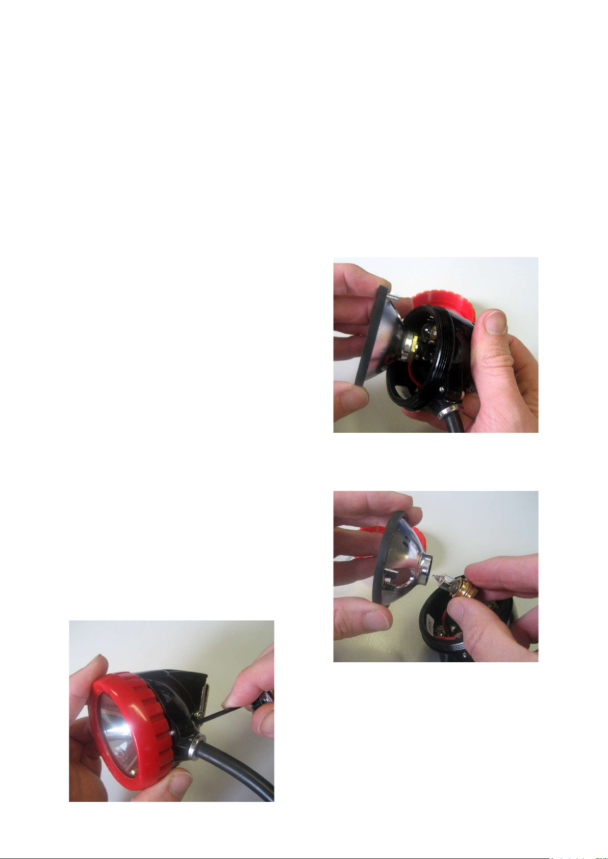
The basis of the headpiece in which some of the
internal connections are integral is as follows:
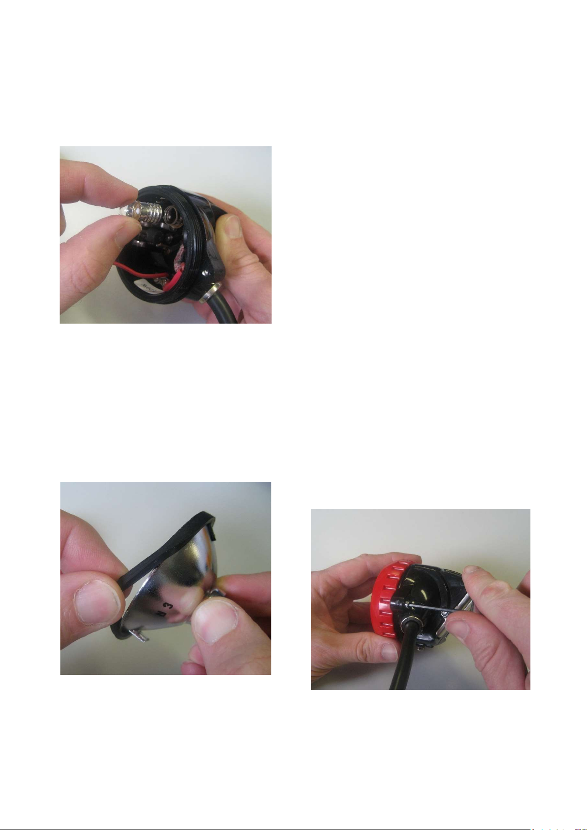
A selector switch is incorporated, which can switch
on either the large main bulb or the small
secondary bulb. The main bulb is held in the
reflector in a focused position by a screwed bush
from which a lead connects to one of the cable
termination points. The small bulb holder is
positioned at the top of the headpiece, being
connected internally to the cable termination. The
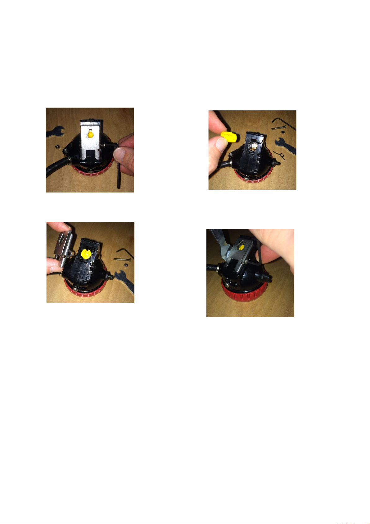
reflector fits over the small bulb and has a rubber
gasket around the rim to seal against the
headpiece lens.
PREPARING THE GL9 or GL16 CAP LAMP FOR
FIRST TIME USE
The battery is packaged separately to the lamptop
and needs to be connected before use.
Tool kit required is M614830
NOTE: THE BATTERY IS TRANSPORTED IN A
PARTIALLY CHARGED CONDITION - EVERY
BATTERY MUST BE FULLY CHARGED
BEFORE FIRST USE.
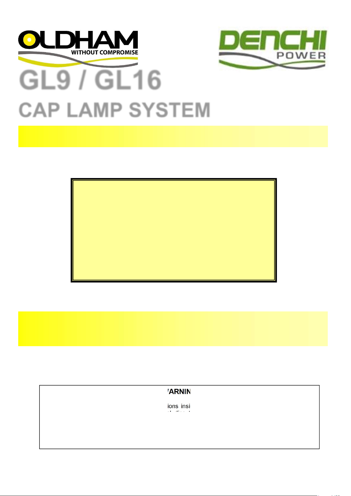
Remove the battery from the shipping box and
check for damage. The battery is supplied with the
encapsulated fuse fitted, terminal nuts and
washers.
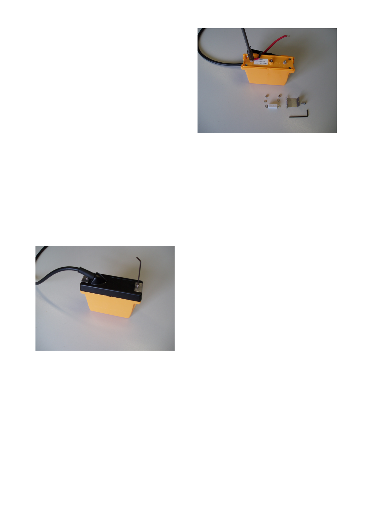
Remove the nut and washer from the positive end
of the fuse (marked +). Place the ring terminal of
the red wire onto the terminal post, replace the
spring washer and nut, and tighten to 0.5Nm.
Remove the nut and washer from the negative
terminal (not connected to the fuse) and place the
ring terminal of the black wire onto the terminal
post, replace the spring washer and nut, and
tighten down to 0.5Nm.
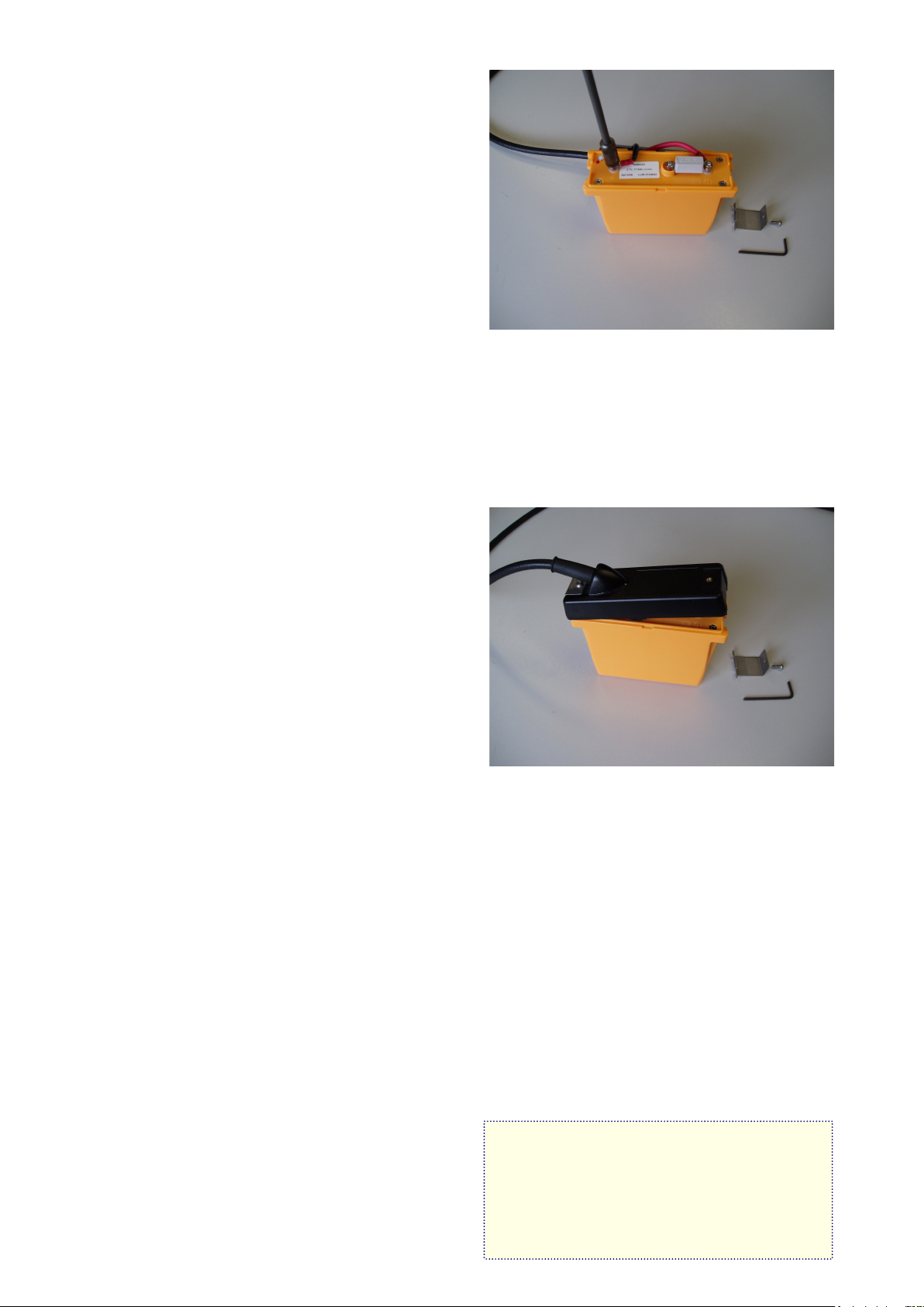
Hook the cable exit end of the battery cover onto
the battery.
Check that the cables are not trapped under the
edge of the cover then press down into position.
Secure the cover in place with the clip and M4
mushroom head socket screw.
Battery charging
WARNING
Li Ion batteries must only be charged on a
specific charger with a Li Ion charge profile. If
the battery is charged on a standard GT
caplamp charger the battery will be damaged.
For charger information and how to convert
existing charger software please consult the
Caplamp Charger Manual.
Every battery must be charged before it is used for
the first time.
Never discharge completely!

4
Charging before first use:
1. Allow the battery to remain on charge for 24
hours.
2. After a working shift, the battery should be
placed on the charger, following the
instructions included with the charger, and left
to charge. The charger automatically switches
off when the battery is completely charged
3. If cap lamp needs cleaning, use a mild
detergent and wipe. Do not submerge in water.
Battery Storage
All stored batteries should be given a 24-hour boost
charge 3 months after receipt and thereafter at 6-
monthly intervals until use, where they should
again be fully charged before being placed into
regular service.
Recommended storage temperature: 0oC to 27oC.
Replacing battery
1. Remove one M4 button head socket screw
from the end clamp holding the cover as
shown.
2. Un-clip the clamp and slide off the cover to
cable end.
3. Remove the positive cable lead (red)
4. Remove the fuse
5. Remove the negative lead (black)
Replacing battery cover
1. Replace the fuse; fit the nuts to hold the fuse in
place
2. Connect the red cable to the positive battery
terminal.
3. Connect the black cable to the negative battery
terminal to ensure correct polarity.
4. Tighten the cable leads down with terminal
nuts to 0.5Nm.
5. Replace the battery cover.
Note:
Ensure that the cable leads lie properly on the
battery top without being trapped or pinched.
USING THE GL9/GL16 CAP LAMP SYSTEM
The G headpiece is made up of the lamp-housing
which contains the following parts:
- Bezel (ring)
- Lens (glass)
- Gasket
- Reflector
- Main bulb
- Secondary bulb
The on-off switch knob is located on the side of the
headpiece. To operate the lamp:
1. Turn the switch knob clockwise to main bulb or
anti-clockwise to secondary bulb.
2. After use turn the switch knob until both bulbs
are off.

5
Repairing the headpiece
Only the small insulated screwdriver (P/N 201042)
should be used as this allows the screws to be
secured tightly without fear of a short-circuit or
other damage.
1. The switch should be placed in the off position
and the battery fuse removed (see section cap
lamp system) before disassembly of the
headpiece. When reassembling the headpiece,
ensure that the sealing channel is correctly
fitted around the reflector.
2. The reflector is located by two projections which
fit either side of the pin that rests against the
envelope of the pilot bulb.
3. The bezel ring should be screwed down firmly
while holding the glass firmly down with your
thumb.
4. The lock pin placed so that it fits into one of the
recesses of the bezel ring and firmly screwed
tight. The lock screw can be sealed with wax –
if applicable.
WARNING
It is essential that all contacts in the headpiece
are tight, so that no electrical resistance is
incurred which might increase the time
necessary to obtain an efficient charge or
possibly reduce the light output of the lamp.
In order to obtain the maximum light possible,
the outside of the lens glass should be cleaned
thoroughly.
REPLACING BULBS
(MAIN AND SECONDARY BULB)
Removing the Bezel ring
1. Remove wax seal (if applicable) from lock
screw.
2. Unscrew lock screw by using special Allen key
P/N 237642
3. Unscrew and remove bezel ring from
headpiece housing while holding the glass
firmly down with your thumb
4. Remove glass (lens) and reflector with sealing
channel from headpiece housing.
Note:
Inspect all parts for cracks or other damage.
Replacing the main bulb
1. Lift reflector out of housing, making sure not to
break the bush connection.
2. Unscrew reflector from bush by holding bush
and unscrewing reflector.
3. Remove main bulb.
4. Place the new main bulb in the reflector.
5. Hold the bush and screw the reflector onto it.
Replacing secondary bulb
1. Remove bezel ring (use Remove bezel ring
procedures).
2. Remove reflector from headpiece housing.

6
3. Unscrew secondary bulb from side socket
assembly of headpiece housing.
4. Thread the new secondary bulb into the socket
assembly (do not over-tighten).
5. Place the hole in the reflector over the
secondary bulb.
6. Reassemble the glass (lens) and bezel to the
headpiece assembly.
Replacing the reflector
1. Remove the bezel ring and lens.
2. Remove the reflector from main bulb bush
connection.
3. Remove gasket around reflector.
4. Place the gasket around the new reflector.
Ensure the gasket is in place all the way
around reflector.
5. Thread the reflector onto the bush connection.
6. Reassemble the lens and bezel ring (see
Reassembling of bezel ring).
Replacing the Cable
1. Remove the cable from the battery
terminals.
2. Cut the cable tie which secures the cable
under the battery cover, and gently pull the
cable out of the battery cover gland.
3. Unscrew the battery collar / cable outlet
gland from the headpiece.
4. Remove the bezel ring (see “removing the
bezel ring”) and glass from the headpiece.
5. Use the spring screwdriver to remove the
screws holding the cable terminals inside
the headpiece, and gently pull the cable
out of the side aperture.
Note: Take care to note the correct polarity of
the cable so that reassembly is correctly
achieved, and the battery is not “reverse
charged”.
6. To replace the cable reverse the above
procedure.
Note:- Always remember to refit the cable outlet
gland over the cable before commencing
reassembly.
Reassembling the bezel ring
When the lens is in position over the reflector, the
bezel ring is locked in position by a hex headed
lock screw that fits into a countersunk hole and
then enters one of the slots in the bezel ring.
The countersunk hole enclosing the lock pin can be
filled with wax if desired.

7
Replacing the lock barrel
If the lock barrel is damaged it may become difficult
to connect the lamp to the charger. In this case, the
lock barrel must be replaced
Use 201520 (M204683) lock contact spares kit.
1. Undo the M4 lock nut and remove the dome-
head screw that runs through the charging
contact housing.
2. The metal cap-clip can be lifted off and set to
one side (take care not to lose the spring clip).
3. Remove the lock barrel and ensure that the
charging contact housing is clear of any debris
before inserting the replacement lock barrel.
4. Holding the lock spring in position, refit the cap-
clip cover, insert the dome-head screw and re-
tighten the M4 lock nut.

8
GL9/GL16 DIAGRAM – ITEM LIST
200005 (M271551)
GL9 caplamp (complete)
200001 / 200003 (M247651/M261651)
GL16 caplamp complete
201501 (M200101)
Headpiece shell
201509 (M201121)
Bezel ring (red)
201504 (M200131)
Glass lens
201508 (M200411)
Sealing channel
201515 (M203827)
Reflector
201506 (M200323)
Small bulb socket
201500 (M259130)
Main bulb 4V 48 Lumen Halogen
201503 (M200130)
Small bulb 4V 0.46A
201507 (M200383)
Prefocus reflector Bush and connection
201516 (M203456)
Cable 1.59m
201523 (M204983)
Headpiece Contact Kit – “G” type only:
Large bulb/switch connection
Small bulb/switch connection assembly
Switch connection
3/16” B HD screw
201519 (M204583)
Switch Knob Kit – “G” type only:
Switch knob, Switch knob sealing washer
Switch blade, Switch blade cowl
Grub Screw
201521 (M204783)
D and G Cap-clip Spares kit:
Cap clip, Cap clip screw
Cap clip nut, Cap head lock pin
201522 (M204883)
Positive Charging Screw Kit – “G” type only:
Positive contact sealing washer
Charging contact screw
Large bulb socket block
Large bulb socket screw
201524 (M205083)
Cable Terminal Spares Kit - “D” and “G” type:
Cable grip, Sealing collar
Small terminal tag, Large terminal tag
Terminal sleeving red, Terminal sleeving black
Terminal tag (headpiece end)
201520 (M204683)
D and G Lock Contact Spares kit:
Lock spring, Lock barrel
Lock contact, Lock contact screw
Lock contact sealing washer
201545 (M455045)
Plastic Battery Cover (complete)
Clip for standard cover
Screw for plastic cover
Cable gland
Cable tie
203006 (M456623)
L9 Li-Ion BATTERY
203000 (M456323)
L16 Li-Ion BATTERY
206008 (M614830)
Small tools and spares kit for “D” and “G” type
lamps comprising:-
Cable outlet gland key
Allen Key for headpiece lock pin
Insulated screwdriver
Spring screwdriver
Spanner for T5 battery terminal nuts
Spanner for L16 Battery terminal nuts
Spanner for “D”-type switch
Two “OCBL” battery fuses
Note: Only certain replacement items above may
be purchased individually. All others, as noted
above, must be purchased in kit form as this
ensures that other associated parts are also
available for replacement at the same time.

9

10
TROUBLESHOOTING
PROBLEM
CAUSE
Bulb glows dimly, flickers or fails 1. Low battery capacity:
a. Continuous use of battery that has not been fully
charged will cause it to lose its capacity. This may be
corrected by fully recharging the battery for 24 hours.
b. Battery not charged.
2. Loose connections:
a. Gently wiggle or pry each connection on top of the
battery to make sure it is tight and working properly.
b. Check the cables for broken conductors by twisting or
pulling it at various points along its length.
c. Check the headpiece terminals and the electrical
connections inside the headpiece in the same manner
as those on the battery.
d. Make sure the bulb is secure and making good
contact.
e. If the light flickers or dims when any of the preceding
items are being checked, that item should be repaired
or replaced.
Battery appears “dead” and will not operate a. Check that the fuse has not blown
b. Check the cross volts of the battery, if no voltage is
recorded the battery has been over discharged and
must be recovered on a nursery charger.
c. Detach the battery from the headpiece and reconnect
to the nursery charger via the ring terminals, red
positive+ and black negative- , leave on charge for 8
hours before reconnecting to the lamp top and putting
back on the normal charger for 24 hours.
Battery capacity a. The 16 Ah Li Ion battery is designed for 12 hour
operation. Failure to achieve this is probably due to a
high resistant joint in the circuit.
b. Check Headpiece charging connections
c. Check charger.
d. Check battery connections.
IMPORTANT: ALWAYS RECHARGE THE LAMP AFTER USE.
ENSURE THAT ONLY CHARGERS WITH THE
CORRECT LI-ION CHARGE PROFILE ARE USED.

11
Certification, equipment marking and instructions for
compliance with ATEX standards:-
The GL9/GL16 range of caplamps are certified for use in Mines where potentially explosive
atmospheres may exist. The lamps are suitable for M2 Mining applications.
Certification codes are:-
ATEX: SIRA07ATEX9033 Ex I M2 Ex I EN62013-1 Ta = 0oC to +40oC
IECEx: IECEx SIR 07.0018 Ex I IEC 62013-1 Ta = 0oC to +40oC
Warning the correct main bulb must be fitted to ensure the correct temperature classification:
Bulb Type Part Number Description Temp. Classification
B2 201500 (M259130) Prefocus Halogen 4.1v48L T2
B2 not available (M259530) Prefocus Halogen 4v 1.5A T2
B3 201528 (M259230) Prefocus Halogen 4v 0.75A T3
B4 201511(M201230) Prefocus Krypton 4v 1A T4
Lamp Type Reference:-
The lamps can be assembled in a variety of combinations to satisfy customer requirements. The
assembly combination is stated on the certification label and this combination should not be
changed without consultation to Denchi Power Ltd., Caithness, Scotland KW14 7XW.
The type code sequence is as below:-
1 2 3 4
Lamptop type Bulb Battery Cover type Battery type
G Standard B2 P Plastic Cover L9 Li Ion Battery
B3 L Hand Lamp L16 Li Ion Battery
B4 R Remote Take Off
1 2 3 4
Sample type code: - G B2 P L16

12
Use of equipment:-
The user must ensure that the lamp supplied meets the safety standard required for the Zoned
area:-
1. This equipment must only be used in a Category M2 zone without undertaking a full risk
assessment for mine rescue use.
2. Check the temperature classification and ensure the correct main bulb is fitted.
3. Check that the operating temperature range is in the range 0oC to +40oC for Mining.
4. The lamp must not be disassembled in a hazardous area.
5. The lamp must not be charged in a hazardous area.
6. The cap light and battery casings are manufactured from polycarbonate and ABS with
nitrile rubber seals. The performance of these materials, with respect to attack by
aggressive substances that may be present in the hazardous area, shall be taken into
account before the equipment is used.
7. Plastic surfaces may cause propagating brush discharges. Propagating brush discharges
are caused by non-conducting fluid flow over a non-conducting plastic surface. The cap
lights shall not be used in areas where a high fluid flow over the plastic surfaces may occur
(for example in the case of a ruptured process pipe or compressed air pipe).
Special Conditions for Safe Use:
There are no special conditions stipulated within the certification.
Denchi Power Ltd.
Denchi House, Thurso Business Park,
Thurso, Caithness, KW147XW
URL: www.oldhamcaplamps.com
Email: [email protected]
Tel.: +44 (0)1847 808000
August 2016
This manual suits for next models
1
Table of contents
Popular Outdoor Light manuals by other brands

Ledino
Ledino Charlottenburg series instruction manual

oluce
oluce SUPERLUNA 397 Mounting instructions

LIGMAN
LIGMAN ALD-30171 installation manual

Good Earth Lighting
Good Earth Lighting SE1216-BRS-02LF4-G quick start guide

marset
marset Lluis Porqueras Funiculi fabric A Assembly instructions

Urban Barn
Urban Barn 216637 Use and care guide

Sunna Design
Sunna Design SOL UP1 user manual

LIGMAN
LIGMAN VA-20023 installation manual

Endon
Endon Burford 76549 Installation and safety instructions

shada
shada LED's light OUTDOOR Series quick start guide

Saxby Lighting
Saxby Lighting EL-40094 Instruction leaflet

Kenroy Home
Kenroy Home Canterbury 93277 Use and care guide