OleumTech Wio RM4 User manual

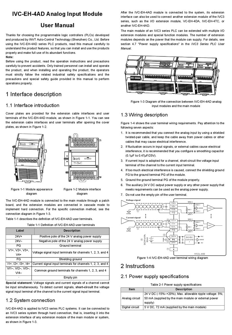
NEMA-Type
Enclosure
9-30 Vdc
(Reverse polarity protecon)
Install antennas
10 above the ground.
Antennas must match
the system’s
Radio Frequency (RF).
Direconal antennas must be
poinng at each other.
Use low loss antenna
cables and connectors.
Installing lightning
arrestors are strongly
recommended.
Make a hole at the boom
of the enclosure to run
wires and cables.
Weatherproof all exterior
connecons and seal all openings
to the enclosure.
6. Installaon
Quick Start Guide
Wireless I/O System - RM4
1. Before You Begin
2. Required Items
- BR-xxxx-RM4 Radio Kit with Onboard I/O
- (2) 9-30 Vdc power sources
- Technician’s screwdriver (flathead)
- (2) 35 mm standard DIN rails (35 x 7.5 mm)
- (2) NEMA 4X-type enclosures for outdoor installaon
- (2) antennas (must match system’s RF type)
- (2) low loss antenna cables, SMA to N (male)
- (2) low loss antenna cables, N to N (male) (oponal)
- (2) lightning arrestors (strongly recommended for outdoors)
- Weatherproofing tape/sealant material
- Wire (solid/stranded AWG 28-12 gauge)
1. The system offers two Tx speeds: 1 sec (def.) or 400 ms
Use the Tx buon to switch between speeds.
2. Device reset: hold down the Tx buon for ~4 seconds unl the
LEDs are exnguished. Power cycling will also reset the device.
Ensure the installaon of the system meets applicable
state and naonal electrical code requirements.
The installaon of the system should only be
performed by a qualified installer.
When connecng the device to an external power supply,
do not exceed the defined voltage: 9-30 Vdc max.
Contains no user serviceable parts. Unauthorized
modificaon to device or supplied accessories may
damage devices and void warranty.
This product is NOT intended for use in hazardous locaons.
Do NOT install or mount on an applicaon with
high vibraon.
The WIO® System must be installed within an
enclosure that requires a tool to access. This is to
prevent inadvertent disconnecon of any of the power
wiring, signal wiring or communicaon cables.
80-3159-001_C
3. Hardware Overview
- Operang temperature range: -40 ˚C to 80 ˚C
7. RF Best Pracces
4. RF Transmission (Tx) Speed / Device Reset
Go to www.wio.oleumtech.com to view or download the
full User Guide for detailed installaon and other
helpful informaon.
RADIO A RADIO B
P1 - Analog Out 1
P2 - Analog Out 2
P4 - Power 9-30 Vdc
P3 - Digital PIO 1/2
Spring-loaded
Latching Clip
DIN Rail Hook
DIP Switches 1-8
SMA Female
P1 - Analog In 1
P2 - Analog In 2
Tx Speed / Reset Buon
Mini-USB
Firmware Upgrade
Diagnosc LEDs RF/PIO
P4 - Power 9-30 Vdc
P3 - Digital PIO 1/2
1. RF Diagnoscs
5. LED Diagnoscs
Flashing Green:
Flashing Yellow:
Solid Yellow:
PIO
RF
Good RF signal: -40 dB (best) to -94 dB
LED flashing speed also indicates
Tx speed.
Weak RF signal: Worse than -94 dB.
RF failure.
2. Digital PIO Diagnoscs
Solid Green:
Solid Red:
Indicates both PIO direcons are
setup correctly.
Indicates when one or both PIO
direcons are setup incorrectly.
Check PIO DIP switches.
www.prosoft-technology.com
1.661.716.5100
1. Perform a RF survey prior to installaon.
2. Use high quality antennas and low loss cables and fings
for achieving the best possible wireless performance.
3. Having a clear line of sight between antennas (Fresnel zone)
is ideal for achieving best RF signal quality.
4. When seng up and installing antennas, avoid walls,
tall buildings, trees, and other solid obstrucons for
improving RF signal quality.
5. Install antennas at least 10 above ground when possible.
6. When using direconal antennas, be sure to point the
antennas at each other and be sure to use correct
antenna orientaon.
7. Be sure to install omni-direconal antennas in vercal posion
or perpendicular to the ground.
8. Be sure that there are no loose connecons.
Securely ghten all cable connecons and wire terminals.
9. Be sure to waterproof all exterior cable connecon using high
quality sealing tape.
10. Once the WIO System is up and running, use the le LED
to diagnose RF health.

13. Transmit Power Seng - 900 MHz Only8. Power Wiring
9. Analog 4-20 mA Inputs, Radio A
This system allows you to control the output states when
RF communicaon failure occurs. When RF is lost for ten
consecuve seconds or more, the system will automacally
drive outputs to their predetermined fail safe states. Use
the dedicated DIP switches to control the fail over behaviors.
1. Analog fail safe modes (DIP 4 and 5 on Radio B)
Applies to both outputs.
11. Digital Programmable I/O (PIO)
1. Digital/discrete input wiring
Only Radio A is equipped with analog inputs.
This system is equipped with two digital programmable I/O.
Using dedicated DIP switches 1 and 2, you can control the
signal direcons independently.
If Radio A = Input, Radio B must = Output and vice versa.
Otherwise, PIO LED will turn red indicang signal direcon error.
Factory default PIO sengs: Radio A = DI ; Radio B = DO
Note that DIP switch posions for In/Out are reversed
on Radio Module A and B.
Must reset device aer modifying any DIP switch sengs.
Be sure to set Fail Safe output mode: Off (default) or On.
The 900 MHz system is equipped with two adjustable
transmission output sengs. Use DIP switch 6 to select
output power. Both Radio Modules must match power.
140 mW (default) or 1 W
14. RF Channel - 900 MHz / 2.4 GHz Only
900 MHz and 2.4 GHz systems offer mulple RF channels
to create beer RF isolaon for beer performance.
Use dedicated DIP switches to set RF channel.
900 MHz system offers channels 0-3 while 2.4 GHz system
offers 0-7 channels.
The RF channel or DIP paern on both Radio Modules
must match. Some examples of how to set RF channel:
15. Using PIO to Monitor RF Health
Using the following logic, you can ulize either PIO channels
to monitor the RF health of the system from a connected
logic controller:
1. Select a PIO channel.
2. Set the PIO signal direcon using DIP switches.
3. Set DO fail safe output mode to off on the output side.
4. On the Radio Module with PIO set as input, place a jumper
wire to e DI to the ground terminal to create “always on.”
5. Tie the output to a logic controller or any device monitoring
the DO state.
6. During normal operang condions, the DO will be on.
7. When the RF communicaon is lost, the system will
de-energize the output to nofy the change in condion.
2. Digital/discrete output wiring
Power - P4
12. Fail Safe Output Operaon
©2019 OleumTech Corporaon. All rights reserved. OleumTech and WIO are registered trademarks of OleumTech Corporaon in the United States.
Specificaons, design, product descripons, and availability subject to change without noce.
9-30 V GNDGND
Reverse Polarity Protecon
10 11 12
DI 2 GNDDI 1
7 8 9
DO 2 GNDDO 1
7 8 9
1. 4-20 mA input wiring - P1 and P2
10. Analog 4-20 mA Outputs, Radio B
4-20 mA output wiring - P1 and P2
Only Radio B is equipped with analog outputs.
SENSOR
N/C
+
9-30 Vdc
N/C
SENSOR
+
_
EXT.
POWER
+
_
S- COMVS
AO 1/2 Fail Safe
Last
Known
Value
<4 mA
AO 1/2 Fail Safe
>20 mA
AO 1/2 Fail Safe
Fail over to Last Know Value (Default) Fail over to Less than 4 mA
Fail over to Greater than 20 mA
>20 mA
AO 1/2 Fail Safe
Fail over to Greater than 20 mA
2. Digital fail safe modes (DIP 3)
Applies to both outputs.
O
DO 1/2 Fail Safe On
DO 1/2 Fail Safe
Fail over to Off (Default) Fail over to On
RF Channel (0-7)
0
0
0
Both Radios
Must Match
Pattern
Channel 0 (Default)
RF Channel (0-7)
0
0
01
Both Radios
Must Match
Pattern
Channel 1
RF Channel (0-7)
0
0
0
Both Radios
Must Match
Pattern
2
Channel 2
RF Channel (0-7)
0
0
01
Both Radios
Must Match
Pattern
2
Channel 3
RF Channel (0-7)
0
0
0
Both Radios
Must Match
Pattern
2
4
Channel 6
RF Channel (0-7)
0
0
0
Both Radios
Must Match
Pattern
1
4
Channel 5
PIO2 GND
INPUT
DI1
Create “alway on”
condion
On = RF OK
Off = No RF
7 8 9
PIO2 GND
Logic
Controller
Example shown using PIO 1
DO1
7 8 9
OUTPUT
Must reset device aer modifying any DIP switch sengs.
3. External Loop Power
2. Internal Loop Power
VS/External Power (min) = 7 Vdc + Max Current (Amp) * Rloop
Rloop = Total Loop Impedance
*A 250 ohm Resistor may be required depending on the design
of the third-party 4-20 mA input module.
250 ohm
Resistor*
Measurement
Electronics
4-20 mA
+
_
PLC Input Module or
Process Controller
N/C
V+GND GND
+_
GND
POWER
SUPPLY
S+
10 11 12
Quick Start Guide
Wireless I/O System -RM4
80-3159-001_C
Accepts Dry Contact (Internal 3.3 Vdc Pull-Up),
Open-Drain (NPN) and Level Output (0 - 30 Vdc Max.)
Input Voltage Threshold:
Signal "H", Vi > 1.85 Vdc
Signal "L", Vi < 1.03 Vdc
Open Drain (NPN) Outputs
Inducve Load (Sink Current): 1A/30 Vdc Max.
Voltage Level Output:
Internal Pull-Up: Signal "H", Vo = 3.3 Vdc
Signal "L", Vo = 0.2 Vdc
Accepts Oponal External Pull-Up, 30 Vdc Max.
Requires 10 K Resistor
Other OleumTech I/O System manuals


