THE
DE
523
AND
CASSETTES
SYSTEM
CASSETTE
HANDLING
It should be noted
that
the
correct
handling of
cassettes
is of prime importance.
To
insert
the
cassette
into
its
compartment:
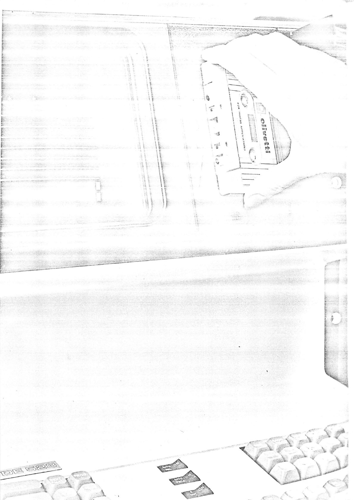
1. Open the compartment door by pressing the catch downwards.
2. Insert the cassette into the compartment by holding the top and bottom of the
»cassette between the index finger and thumb (see photograph opposite). Special
care
should
be
taken
not to
handle
the
exposed
part of
the
magnetic
tape.
3. Slot the cassette into the compartment by inserting the right edge slightly ahead
of
the
left
edge
(see
photograph
opposite).
4.
Close
the
compartment
door.
To
remove
the
cassette
from
its
compartment:
1.
Open
the compartment door
by
pressing the catch
downwards.
2.
Hold
the top and
bottom
of the cassette and
move
it slightly to the right before
removal. The left
edge
of the
cassette
should be withdrawn first.
NOTE:
AT
ALL
TIMES THE CASSETTES MUST BE
REWOUND
PRIOR TO THEIR
REMOVAL.
SIZE
OF
CASSETTE
TAPE
The cassette tape is
280
feet
(90
metres)
long
with
the effective capacity of each
cassette consisting of 1.000-2.000 records depending on record size,
216-80
characters
respectively,
and
the
size of inter-record
gaps.
RECORD
HANDLING
TECHNIQUES
I
The
cassette
recorder
feature
provides
the
terminal
with
the
ability
to
read,
write,
I ^
backspace,
insert,
write
file
marks,
and
rewind
cassette
tapes.
The
operations,
I
'W
themselves,
can
be
performed
under
the
control
of
format
programs
provided
with
the
I
cassette
system.
Sincc
the
recorders
share
the
same
interface,
it
is
not
possible
to
I
overlap
operations
on
the
first
recorder
with
those
of
the
second
recorder.
It
is,
however,
I
possible
to
overlap
cassette
input/output
operations
with
other
peripheral
operations,
i
providing
the
terminal's
overlap
rules
are
satisfied
(see
DE
520
General
Manual,
V
pSiQQ
14).
I
4
5
^
READ
The Read operation reads the next available record
from
the selected cassette into the
buffer specified by the terminal control.
If
the "Clear Leader" is detected prior to the
initiationof the read operation the cassette recorder assumes that it is at the beginning-
of-tape
(BOT),
and advances the tape
beyond
the Clear
Leader.
If
Clear Leader is
detected during a read operation the cassette recorder assumes it is at the end-of-tape
(EOT),
the tape is retarded
0.25
inches
from
the Clear Leader and the read operation
terrninales
with
the
message
EOT
displayed
on
the
screen.