Olympus CLV-U20 User manual

OLYMPUS
CLV-U20
EVIS UNIVERSAL LIGHT SOURCE
The
user
of
this
equipment
should
be
thoroughly
trained
in
the
applicable procedure.
Furthermore, failure
to
read
and
thoroughly
understand
the contents
of
this
instruction
manual
may
result
in serious
injury
to
the
patient
and/or
user.
It
is essential
to
follow
the
instructions
contained
in
this
and
other
manuals
which pertain to
any
equipment
and
accessories
used
in
conjunction with this
equipment.
Possible injuries related
to
endoscopic
procedures
may
include electric shock, explosion, burns,
perforation,
hemorrhage, etc.
Fai/ure to
follow
these
instructions
may
also
result
in
damage
to
and/or
malfunction
of
this equipment.
r---------
WARNING
t;1J
(}Aj
III
m;
~
fIJ
JtT
'IJ
,fJI
()()
,)
1-
CAUTION
Federal (USA)
law
restricts this device to sale
by
or
on
the
order
of
aphysician,
OLYMPUS·


The
Olympus
CLV~U20
has been
designed
for
endoscopic
diagnosis,
treatment
and
photo
documentation
in
conjunction
with
Olympus
endoscopes,accessories
and
other
ancillary
equipments.
Do
not
use
the
instrument
for
any
purpose
other
than
its
intended
application.
Please
read
this
entire
manual
carefully
before
using
the
instrument.
It
contains
pertinent
information
on
the
proper
care
and
handling
of
your
videoscope.
Although
videoscopes
by
nature
aredelicate
instruments,
proper
handling
and
cleaning, as
described
in
this
manual,
will
greatly
reduce
the
need
for
costly
repair
and
maximize
the life
of
your
new
instrument.
This
manual
describes the
recommended
procedures
for
preparing
and
inspecting
the
equipment
prior
to use.
It
does
not
describe
how
an
actual
procedure
is to be
performed
in
detail.
Nor
does
it
attempt
to
acquaint
a
beginner
with
endoscopic technique
and
the
medical
aspects
of
endoscopy. This
instrument
should
be
used
only
by
physicians
who
have
received
thorough
previous
training
in
the
art
of
endoscopy.
The
safety
and
performance
of
an
endoscopic
system
depends
not
only
on
the
endoscope
but
also
on
any
ancillary
equipment
used
with
it.
Safety
precautions
must
be
exercised
when
handling
electrical
equipment
to
prevent
operator/patient
shock.
If
you
have
any
questions
concerning
the
material
contained
in
this
manual
or
concerning
the
operation
or
safety
of
the
equipment,
please
contact
your
Olympus
representative
or
the
nearest
Olympus
office.

SAFETY
SYMBOLS
Replace
the
Lamp and Filter-2
following
the
instructions
(Section 9-1 Replacement
of
Lamps;
9-2
Replacement
of
Filter-2l.
The lamp and heat
sinks
are extremely hot immediately after
use.
Allow sufficient time for
them
to
be cooled before
lamp
replacement.

CONTENTS
1FEATURES AND MAIN SPECIFICATIONS 1
1-1 Features 1
1-2
Main Specifications 2
1-3
Safety Precaution 4
2DESCRIPTION OF CONTROLS 6
3CONSTRUCTION 9
4STANDARD SET 10
5PREPARATION
FOR
USE
11
5-1 Installation
of
the
Light Source
11
5-2
Connection
to
AC Mains Supply..................................................................................
12
5-3
Preparation
of
the
Videoscope 13
5-4
Preparation
for
Air
Feeding/Water Feeding and Suction 13
5-5
Connecting
the
Endoscope to
the
Light
Source 14
5-6
Preparation
for
Still Photography................................................................................ 15
5-7
Preparation
for
Cinematography, CCTV and Polaroid Photography........................ 15
6INSPECTION
OF
ENDOSCOPIC SYSTEM 16
7OPERATING
THE
LIGHT
SOURCE
24
7-1 Use in
Combination
with
the
Videoscope 24
7-2
With
Fiberscope 25
7-3
With
Rigid Scopes 26
7-4
Cinematography
and CCTV
27
7-5
After
Use
27
8
CARE
AND STORAGE 28
8-1 Care after Use 28
8-2
Storage 28
9MAINTENANCE 29
9-1 Replacement
of
Lamps 29
9-2
Replacement
of
Filter·2
31
9-3
Resetting
the
Circuit Breaker
31
9-4
Cleaning
the
Ventilation Grills
32
9-5
Periodic Inspection 32
10 TROUBLESHOOTING GUIDE 33
11
ENDOSCOPIC SYSTEM CHART (EVIS/OES SYSTEMS) 35
11-1
OES
System
Chart 35
11-2
EVIS Endoscopic Video
Information
System
37
1
2
3
4
5
6
7
8
9
10
11

1
(j)
z
o
~
U
L.1.
U
UJ
0-
(j)
Z
;:;:
2'
o
z
<t
(j)
UJ
a::
::::>
f-
<t
UJ
L.1.
1.
By
use
of
the mode selector, the instrument serves
as
apossible and universal light source
for OES-fiberscopes, Olympus rigid scopes for
EVIS
100 System (instantaneous single-plate
color chip system), and for
EVIS
200 System (sequencing system).
2.
By
use
of
OES
system,
EVIS
100 system and
EVIS
200 system, the insertion position of the
scope point
can
be
checked by the transillumination function.
3When using
EVIS
100 or
EVIS
200 system, by use of the Foot Switch, the anc'illary equipments
can
be
released.
4.
Combined
with
OES
fiberscope, SC16-10 and rigid scope and SC16-10R, the following
advantages
can
be
offered.
•Photographs under stable exposure
can
be taken
in
short distances.
•Date is visible
in
the viewfinder and imprinted
on
film.
•Remote shutter release using afoot switch frees the endoscopist from finger-tip shutter
operation.
•Indicators
in
the camera's viewfinder predict exposure level before taking photographs and
the exposure level
is
given when taking photographs.
5.
1.5 times the flash output
of
the maximum illumination intensity
of
the light source
is
available.
6.
Flat switches and display panel
can
be easily wiped clean.
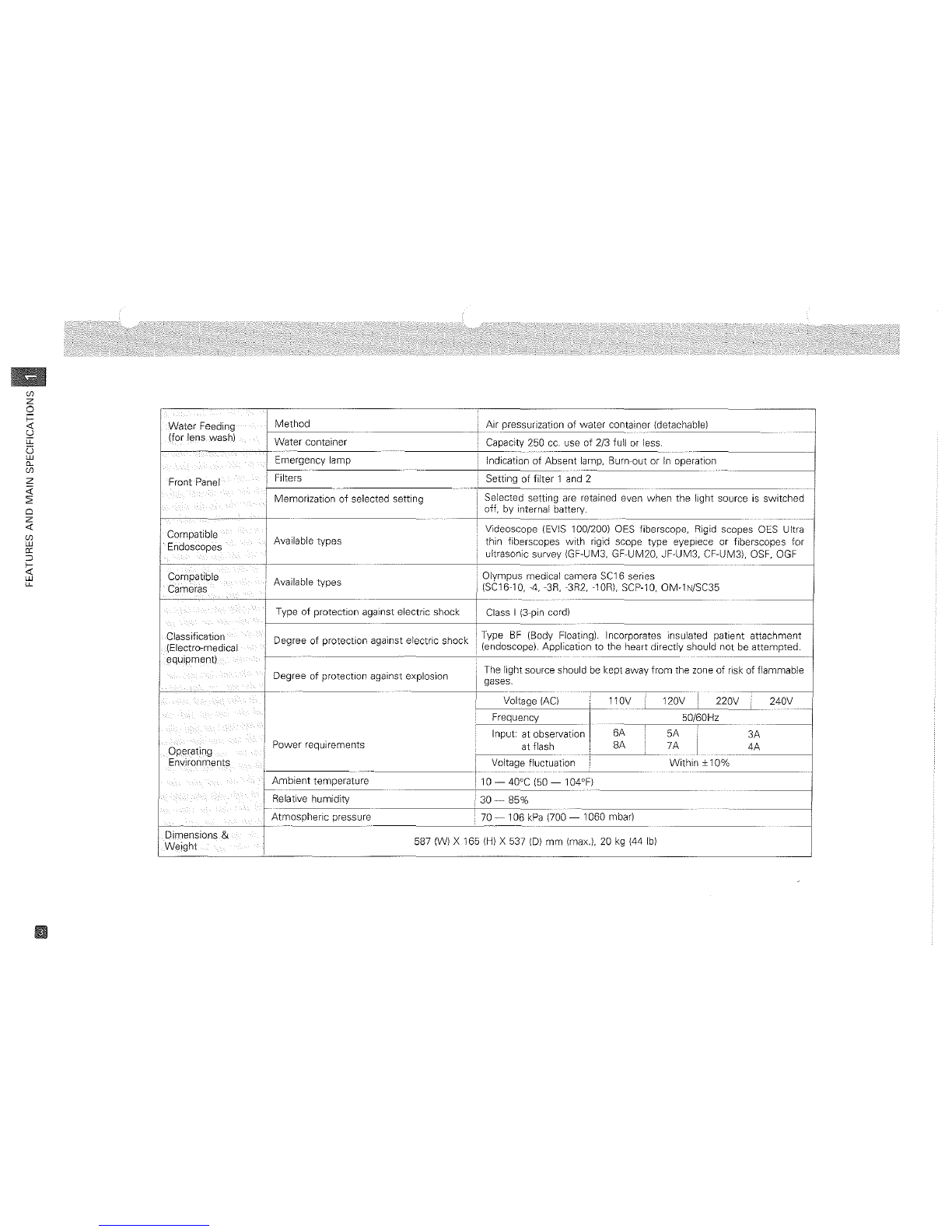
7.
An
emergency lamp turns
on
instantly if the Xenon lamp burns out, to provide illumination
bright enough for endoscope withdrawal. Alight
on
the front panel indicates at aglance if
the emergency lamp
is
not installed,
is
installed improperly or
is
burned out, or
is
lighting
instead of the Xenon lamp.
8.
Air feeding pressure
can
be adjusted
in
three levels.
9.
With no scope and even when Xenon lamp illuminates, illumination light automatically dims
to prevent dazzling and the air feeding pump simultaneously stops.
10. Combined
with
function expansion devices (under development), light source
can
be
more
functionated.

]-2
Main Specifications
Lamp !Xenon short-arc lamp (ozone-free) 300W
l-------
I
Lamp life !Approx. 300 hours on continuous
use'
(over 20,000 flashes)
Ignition
LSwitching
regu~at_or
Illumination 'Light output adjustment ILight-path diaphragm control
1-----"--
Cooling
Forced-air
cooling
----
----
---------
Color
conversion
Filter-2
is
replaceable.
IEmergency lamp Halogen lamp (without mirror) 24V 150W
-
-----
--------------
Emergency lamp life Approx. 500 hours.
--
-~~
-
--
-----
Visual.-observatjon
Adjustment method (Automatic) Servodiaphragm method
•Videoscope Auto exposure sensitivity Setting (Auto) I
17
steps: 1step 1/4
EV
(F;
full admission)
•Cine-
TV
IExposure decreases from INDEX NUMBER
"Full"
to
"5".
,
I
Exposure
control
Auto/Manual; time control
by
light source shutter
--
---_._--
-------
-------
----
--------
Exposure light amount
Flash
output (approx. 1.5 times visual light output)
Still Shutter speed
1/4
to 1/100 sec.
Photography Shortest recycling time i1
sec.
_.
-
----------------
Auto
exposure
sensitivity
setting
9steps: 1step
~
1/2
EV.
Exposure decreases from INDEX
"1"
to
"5"
(or
from "+2" to "-2") with
1/2
EV
per step.
-----------
----
Manual exposure sensitivity setting 10 steps: 1step
~
112
EV,
except for 1
EV
between
"F"
(Fulll
and
"1
".
_._---~~
---
-----------------------
Linear type pump
High: less than 0.5
kgflcm'
(at
flow
rate
0)
Medium: more than 1.6 £Imin. (at 0.09 kgf/cm2)
F~edlng
Pump pressure
(at
output socketl Low: 0.075 -0.15 kgf/cm'
(at
flow
rate
0)
At
"HIGH"
the pressure
is
equivalent to that avai!able by the other light
isource than OES/EVIS.
*On intermittent
use,
the lamp life may differ slightly.
"
m
~
C
:0
m
(j)
::>
z
o
S
~
z
(j)
-0
m
Q
"
(i
~
o
z
(j)

(f)
z
o
~
'd
li-
e;
W
0-
(f)
z
<i'
~
o
z
-0:
(f)
w
0:
o
~
W
li-
Water
Feeding
Method
Air pressurization
of
water
container (detachable)
_____
L..
.•
(for lens wash)
Water
container Capacity
250
cc. use
of
2/3 full
or
less.
Emergency lamp Indication
of
Absent
lamp, Burn-out
or
In operation
j------
Setting
of
filter
1
Front
Panel
!Filters and 2
,
iMemorization
of
selected
setting
Selected setting
are
retained even when the light source
is
switched
off, by internal battery.
--
Compatible Videoscope (EVIS 100/200) OES fiberscope, Rigid scopes OES Ultra
Endoscopes Available
types
thin fiberscopes
with
rigid scope type eyepiece
or
fiberscopes
for
iultrasonic survey (GF-UM3, GF-UM20, JF-UM3, CF-UM3), OSF, OGF
e----- -
-------
Compatible IAvailable
types
'
Olympus
medical camera
5C16
series
Cameras
~C1610,4,3R,3R2,
lOR!, SCP-10, OM-1 N/SC35
Type
of
protection against electric shock !Class I(3-pin cord)
Classification Degree
of
protection against electric
shock
IType
BF
(Body Floating). Incorporates insulated
patient
attachment
(Electro-medical !(endoscope). Application
to
the
heart directly should
not
be
attempted.
equipment)
L--
------
I
!0!:!<I~'
"'
oW",""
'~"~""""'""
The light source should be kept away
from
the
zone
of
risk
of
flammable
gases.
Voltage
(AC)
110V 120V I220V 240V
-----
Frequency I50/60Hz
Input:
at
observation 6A !
5A
I
3A
6
f····
..
:
Power
requirements
at
flash !
6A
7A
4A
peralng
I
---
Environments 'iVoltage fluctuation
Within
±10%
I
Ambient
temperature
I10 -40°C (50 -104°F)
-
--
Relative humidity i
30-
85%
Atmospheric
pressure 70 -106
kPa
(700 -1060 mbar)
,.~-----,-"
---
Dimensions &587 (W) X165 {HI X537 {DI
mm
{max.!, 20 kg (44 Ibl
W~ight

."
m
~
C
:u
m
CIJ
»
z
o
;;:
:J:':
z
CIJ
-0
m
n
Jl
n
~
o
z
CIJ
Flam",a',le gases
CD
The CLV-U20 light source should be used only
in
amedical facility
under
the
supervision
of
a
trained physician.
@The light source is designed (floating)
to
function
integrally
with
insulated patient
attachement
(endoscopes)
to
prevent operator/patient shock. Endoscopes and cameras
to
be used
with
it
should
not
be grounded
in
order
to
prevent
shocks
which
may
be caused
by
leakage
current
from other electrical apparatus applied
to
the
patient
The endoscopist should wear rubber
gloves as an added precaution.
®The housing of the light source must
be
grounded securely and effectively. Do not defect
the
line cord ground connection.
@)
The light source/endoscope combination should never be applied
to
the
heart directly.
@Never install and operate the light source where there
is
the risk
of
flammable gases.
@Keep liquids away from
all
electrical equipment
to
prevent operator shock and instrument
damage. Do
not
use
the
light source if spilled fluids have entered
the
unit.
~
~\,
1\
"
,
Powe'
PIU:~~
Hospital
grade
receptacle
(wall
mains
outlet)
Be
sure
to
connect
the
power
plug
to
a
hospital
grade
receptacle
(a
wall
mains
outlet).
l_l_-3_S_a--'-rfi_
e
_ty_P--'-_re_c_a_u_tio_n_s
-----)::===========
Spillable
liquids

Rubber
gloves
(f)
z
o
i=
«
u
u:
U
LlJ
0-
(f)
Z
;;:
2'
Cl
z
«
(f)
LlJ
a:
:::>
f-
«
LlJ
CL
(j) The light source/endoscope combination should not
be
used in conjunction with:
1.
Electrical apparatus whose safety against leakage current
is
not guaranteed.
2.
Electrosurgical equipment whose safety
in
linked usage is not guaranteed.
®The light source should
be
used
in
accordance
with
the operating conditions described
in
this manual; otherwise, improper performance, compromised safety, or instrument damage
may result.
®Repairs should be carried out only by Olympus service personnel.
,._----------.---.----------
....-
..
_.....
_----------------------.---,
Cpmbinedusewith
equipment
whose
electrical
safety
is
not
guaranteed.
:
.,,
._._
••
c.
__
• ,
_,
•••.•.••••
~
.
__
._, .:
~
:.
----,----_._------
---
-.
-_._---
..
,
...
-
.~------------------_.
----
...
:

2
o
m
CJ1
()
:rJ
~
o
z
o
-n
()
o
Z
-i
:rJ
o
r
CJ1
Filter
Switch
Press to turn 0 N the trans-
illumination indicator.
The light from the endoscope
becomes
brighter
for
9
seconds and automatically
return.
*
With
EVIS 200
system,
the
images
on
the
mon-
itor
get
over-exposed
in
black
or
white.
*The
illumination
returns
to
the
original
level
short-
ly
after
pressing
the
switch
again
while
using
transillumination.
Brightness
Control
Transillumination
Switch
Each
press
to
select "filter-1
",
"filter-2" and
"non".
With aspecial-purpose filter {optional) for
visual observation and photography, press
"filter-2" to give the illumination of "filter-
2".
*"fllter-2"
Is
attached
with
a
light
cutting
filter
{when
Installed) and can
be replaced
with
a
special-purpose
filter
on
request.
*
With
EVIS 200
System,
"filter-1"
cannot
be used.
Press
to
set
CINEnv
exposure level
(at
"AUTO")
or
to
adjust light level (at
"MANUAL)
Exposure
Sensitivity
Selector
Press to set exposure
sensitivity.
FOOT
SW.
";\-'TI~R_
ILL
PHOTO
11
1IN
EX
ADJUS
F
Ll<::l
10+2
Lamp
Life
Meter
Indicates
cumulative
working
hours {approx.)
of
Xenon lamp.
AUTO/MANUAL
Brightness
Selector
Press
to
set
"AUTO/MANUAL"
of
brightness.
*For
other
combinations
than
CINE/
TV,
"MANUAL"
should
be selected
to
avoid
thermal
mucosal
damage
as
weI! as
to
protect
your
eyes. Select
also
the
minimum
necessary
light
level.
*
With
EVIS 100/EVIS 200
Systems,
the
selector
is
automatically
set
to
"AUTO".
AUX
Air
Regulator
Press to adjust
air-
flow
pressure.
AUTO/MANUAL
Exposure
Selector
Press to set AUTO or
MANUAL
for stili photographs Including
polaroid.
IGNITION
Connector
for
Rigid
Scope's
Camera Cord
Connects
with
the camera
cord for SC35 and SC16-10R.
Footswith
Connector
Connects
with
a
foot
release
MB-332.
Mode
Selector
OLYMPUS
@@CLV-U20
POWER
~
ON
Press one of the push-buttons
indicating system names to
select one system.
Output
Connector
Transmits light, electrical
signals and air through the
endoscope.
r-----+---W'\--------I%:\--\--+f------4--....
Lamp
Ignition
Switch
Press to turn on Xenon lamp.
Power Switch
Press the upper portion
of
the
power switch to turn
on
power
source
and
the
power
switch
indicator
turns
on simultaneously.
FRONTPA~

Multiple
LEDs
turn
on
with
light
level
while
at
MANUAL.
At
AUTO, asingle
LED
indicator
turns
on
with
exposure
sensitivity
setting.
Turn
on
to
indicate
at
AUTO
exposure. (SC16-10/0ES
fiberscope
SC16-10R/rigid scope
combination
only).
Turn
on
to
illuminate
for
the
com-
Turn
on
to
indicate
the
bination
excluding
SC35 and
OES
brightness
control is
set
at
fiberscope,
and
also at
"MANUAL"
"MANUAL".
exposure.
\\
Turn
on
to
set
air
Turn
on
to
indicate
the
regulator
switch.
A
single
indicator
turns
on
brightness
control is
set
at
in
accordance
with
index
"AUTO".
number.
\
~
\
Lamp
is
turned
on
when
"fi1ter-1"
~~~
is
selected.
OLYMPUS
J.------
~
CLV-U20
TILL
PH
0
BRIGHT
ESS
f!~l---
I~Bt~=A
-NST
VISHf-L
c;INE'TV
MAX~~
o1
OUTPUT
1=+2
o~
~
c
~2
U
1\2:T1
UU
~
~
Lamp
is
turned
on
when
"filter-2"
oB is selected.
300
L-
~
3
S~RE
~
':-1
\J
cMP Filter selection
switch
MODE
0\J
00
~.
~
pOwER
c
Cl
ILLUM
==--"
~IE~g)
5""-2
MIN~
MAN.D
,DAlTO
ro
~Ar
~
ONEJ'
cB
[AUTO)
[
AUT
9 0
t'---
Lamp
illuminates
MAN MAN.
~
when
transmitted
II
II
IGNITION /I I I
illumination
is used.
OFF
0/
6@AUX
@FOOT
SY.
~
!LAf,!P!L1FE
\I
~.
"WIM"""
\1
Lamp
turns
on
to
warn
of
absent
or
faulty
Turn
to
indicate
Xenon
lamp
and
that
the
spare
lamp
on (halogen) is
lighting
instead
of
Xenon
which
system
is used.
exposure
selector
to
indicate
at
"MANUAL"
lamp.
exposure. Press
brightness
selector
II
to
indicate
at
"AUTO"
Press
AUTO/MANUAL
brightness
control.
exposure
selector
to
indicate
at
"AUTO"
Press
brightness
selector
exposure.
to
indicate at
"MANUAL"
brightness
control.
IDESIGNATION
AND
FUNCTIOt<j
(/)
--.J
o
a:
I-
Z
o
u
"-
o
z
o
t
a:
u
(/)
UJ
o

MAIN
BODY I
Water Container
Receiver
Ventilation
Grill
Connector
for
optional
function
expansion
devices
Connects to apower
unit
for
use
with
function
expansion
devices (under
develop~
ment).
Connector
for
CV-100/200
Connects
to
light source
cable (MD-434) for
CV-
100 and CV-200.
Ratings Plate
•
Ventilation
Grill
Handle
Lowered
when
lamp
access cover
is
used.
Circuit
Breaker
o
m
(f)
n
:IJ
::'1
6
z
o
-n
n
o
z
..,
:IJ
o
r
(f)
Lamp
access
cover
Opens to allow replace-
ment
of Xenon lamp,
emergency
lamp and
filter-2. Power Cord
Protects the light source and the
power source
in
hospital facilities
in
an
emergency.
*Please use
circuit
breakers
(15A~20A)
for
hospital
facilities.
Cord Hanger
Used for winding the
power
cord.

3
Light source cable
.---
IMD-434)
...---
Connection (optional)
....---Connector
for
CV-lOO/200
t==='~
Power Plug
Power Plug
F=:::::\'\;:::::==~
Power
switch
Xenon lamp
Filter
1-----
DC
power
~-"-;'=_
supply
EVIS Video System Center
Syslem
Diagram
for
Light Source
CV
-1
OO/CV
-200
Xenon I
'::==1--
power
rYnt;jr---l~~-
supply
Motor
R.G.B.
Filter
Keyboard
Panel displaY
switch
•
r---"
I
I
I
I
I
I
I
I
I
I
I
I
I
I
I
I
I
I
-~
Output Connector
•
Videoscope
Cable 100/200
I
OES
System I
Photodocumentation
Equipment
lEVIS
100/200 SYSTEM I
EVIS
100/200
Videoscope
CCD
z
o
f=
u
::>
ex:
I-
(J)
Z
o
u
Isolation
Transformer

4
(fJ
-1
J>
Z
o
J>
:0
o
(fJ
m
-1
Do not handle rolighly.
1set
@Vinyl Dust Cover (MD-4481 .
@Foot Holder (MD-5121 .
==~
CD
CD
Main Body
(CLV~U201
.
(including Xenon lamp
and
emergency lampl
ClJ
Water Container
(MD~431
I.
Place for
easy
use
at any time.
/
*Store the instruction manual
in
the vinyl bag and retain for easy
use
at any time.

5
Refer also
to
the instruction manuals supplied
with
the endoscope and photographic attachments.
Place
the
light
source
i
on
astable
base.
place
the
light
source
in
ahorizontal position.
Ventilation
must
not
be
blocked.
{Prevention
of
overheating]
CD
Ensure the safety precautions
in
1-3, page 4
are
met.
@Place the light source on astable surface
in
ahorizontal position.
*
Ventilation
must
not
be
blocked.
*
Ensure
the
stability
of
the
cart
when
the
light
source
is
placed
on
it
.
*Do
not
use
the
side
handle
of
the
light
source
as a
foot
support.
*Please
refer
also
to
the
instruction
manuals
for
TC-Vl,
CV-l00
and
CV-200
when
setting
to
TC-Vl
(Compact
Video
Trolleyl.
*
When
combined
with
CV-l00/200
and
always
set
the
light
source
below
the
video
processor.
@Always
set
the light source using
the
attached
foot
holder (MD-5l21
when
placed on sliding
surface or
in
case the light source moves while
in
use.
D
Please
refer
to
each
instruction
0
manual
for
products.
r-=--:---:--:--:--:---~:c--c::---c-~-c::---------------------------,
!5-1 Installation
of
the Light Source
LlJ
(J)
:::>
a::
o
u.
Z
o
~
a::
:;:
LlJ
a::
"-
..
Use
the
foot
holders
for
stable
placement
of
the
light
source.

1_5_-_2_C_o_n_n_ec_ti_·o_n_f_o_A_e
C
__
.
M_az_·n_s_eS_eu_'P_'P_ly
~
~):===========
CD
Make sure the
power
switch
is
in
the
off
position.
v
"
m
~
"
:to;
is
z
"o
"
c
en
m
The
converter
adapter
from
three
pin plug
to
two
pin plug
cannot
be
safely
grounded
and
electrical
shock
may
Do
not
connect
the
power
cord
for
the
light
source
to
the
outlet
for TC-V1.
@The power-cord plug
must
be
connected to agrounded hospital grade outlet or awall
rna-Ins
outlet
13-cord
outletl.
*Do
not
use
converter
adapter
from
three
pin
power
plug
to
two
pin
power
plug
for
safety
precautions.
*
Connect
the
light
source
directly
to
hospital
grade
receptable
or
wall
mains
outlet
without
connecting
to
table
tap
for
safety.
*
Firmly
set
power
cord
during
inspection.
Do
not
apply
excess
force
to
power
cord
by
bending,
pulling,
twisting
and
pressing.
*
When
combined
with
TC-V1
(compact
video
trolley),
do
not
connect
the
power
cord
of
light
source
to
the
secondary
outlet
of
TC-V1
to
prevent
malfunction
due
to
the
subsequent
power
voltage
lowering.
Be
sure
to
connect
the
power
cord
directly
to
hospital
grade
receptacle.
*Refer also
to
the
instruction
manuals
for
combined
instruments
being
used.
@Connect the power cord properly
to
the "HOSPITAL GRADE" receptacle or the wall mains
outlet that meets the input requirements indicated on the ratings plate on the rear panel
of
the light source.
[Shock
prevention]
Ratings
plate
~-J®
Power
plug
~
Hospital
grade
receptacle
{wall
mains
outlet)
Always
connect
the
power
cord
properly
to
the
"HOSPITAL
GRADE" receptacle or the
wall
mains
outlet.
Power
switch
should
be
in
the
"OFF"
position.

w
(f)
::J
a:
o
CL
z
o
~
a:
<>:
0-
w
a:
0-
5-3 Preparation
of
the Videoscope
Select
EVI~
100
or
EVIS 200. Refer
to
the
instruction manuals of
the
Vjdeoscope, Compace Video Trolley, and
EVIS
Video
System Center ICV-l00/CV-2001
in
use.
I'"
!,i;g~I_~'"
:"'~r,,:~'i.!~
CD
Prepare the
EVIS
Video System following the instructions found
In
the manuals
of
the
EVIS
',8'
,-"
I "
I"
-":"'.
J~IJ~IJ,~~
Videoscope, Compact Video Trolley, and
EVIS
Video System Center CV-l00/CV-200,
1§]~['J:lJ1
-8i
"'"
-1-"",l:J
@Ensure that the
power
switch
is
'OFF' and then connect the light source cable IMD-434)
option) between the 'light source' connector on the back of the CV-100/200, and the 'CV-
I
.:g;"o'
@.QQT'W.
'
"""
J""">e'
I100/200' connector on the back of the light source.
'---J
@Use the mode
switch
and select the
EVIS
Video System
to
be
used:
In
CV-100(200 When using the
EVIS
100, select
~.
I!
I
~CV-100/200connecto~
When using the
EVIS
200, select
~.
III~
Light
source
connE!c~,or
*
When
EVIS 100
or
200 is selected,
photo
sensitivity
will
not
be indicated,
J~
"""
=
rnU
Light
source
c~
5-4
Preparati,Qn
forAir
Feeding/Water Feeding
and
Suction I
2/3
T
-L
Water
feed
tube
Suction
tube
CD
When
water
feeding
is
needed, fill the container approximately 2/3 full
with
clean water,
Tighten the
cap
securely
and
then hand
the
container
on
the container receiver.
*
Change
the
water
daily,
*Use
only
clean
water
(distilled
or
sterile)
to
prevent
clogging
of
the
water
channel.
*
If
a
poor
connection
with
the
scope
has caused
water
to
spill
onto
the
equipment,
wipe
it
completely
dry
with
a
soft
cloth,
etc.
CV
Connect the feed tube of the
water
container
to
the connector on the scope.
@If suction
is
needed, connect the tube from the suction
pump
with
the scope suction
connector.
*Check
the
suction
pump
carefully
for
leakage
and
electrical safety.
*:
Use
only
electrically
insulated
suction
tube.

5-5 Connecting the Endoscope to the Light Source
II
Vide,osCO!lle Cc,nne[:tion
"
:D
m
~
:D
~
o
z
"o
:D
C
(f)
m
Do
not
attach
or
detach
the
videoscope
cable
with
power
ON.
CD
Turn
OFF
the light source.
(2)
Turn
OFF
the
EVIS
Video System Center ICV-l00/2001.
@Push the scope into the scope socket until aclick
is
felt.
@Attach the videoscope cable
to
the electical connector.
1.
Align the dots
on
the cable and the scope, and push together firmly.
2.
Rotate the ring of the videoscope cable while pushing the cable
and
the scope together
until aclick
is
felt.
*
Be
sure
that
the
power
switch
of
the
EVIS
Video
System
Center
remains
'OFF'
when
attaching
or
removing
the
videoscope
cable. The
CCO
may
be
destroyed
if
power
is
left
'ON'
during
attachment.
*To avoid
damage
to
the
ceo,
do
not
touch
the
electrical
contacts
inside
the
electrical
connector.
CD
Securely connect the scope into the scope socket until aclick
is
felt.
I
~~~&~~~
or' fiberscope lfor ultrasonil:.
surVE
Videoscope cable
[Connection
of
videoscopeJ
[Connection
of
fiberscope]
CD
Securely connect the scope into the scope socket until aclick
is
felt.
II
Connection
CD
Securely connect the light guide of the rigid scope into the scope socket.

I5-6 Preparation
for
Still Photography
w
(J)
::J
0:
o
"-
z
o
~
0:
«
Il.
w
0:
Il.
Camera
cord
[Camera
cord
connection]
Refer also to
the
instruction manuals for endoscopes and photodocumentation equipment to
be
used
with
the light source.
CD
Refer to the following table.
Endoscope Camera X •
FP
contact IShutter speed Film Filter
switch
f--
SC16-10 --No. 1610-0
Fiberscope SC16-4 !-No. 1604-0
I--
!
NEktachrom
SC35 X1/4 sec. (ISO/ASA 200)
OFF
(Filter-1/2
SC16-lOR --INo. 1610-0 indicator
IS not lighted.)
SC16-3R XNo. 1604-0
Rigid SC16-RR2 -
fOM-1N X1/4 sec. Ektachrom
SC35 :IISO/ASA 400)
CD
For rigid scope, camera cord (EC-26, 27 or 28)
is
plugged into rigid scope's camera connector
of light source.
(2)
Foot release
is
plugged into the connector for foot release
when
necessary.
*This
application
is
only
possible
for
the
combination
of
OES fiberscope/SC16-10 and
rigid
scope/SC16-10R.
15-7
Preparation
for
Cinematography, ccrv
and
l'olaroid® Photography
Refer also
to
the instruction manuals for endoscopes, photography devices and
OES
TV
system (OTV-F2/S2) to be used
with
the light source.
CD
For cinematography, refer to the endoscope instruction manual.
(2)
For cinematography, prepare cine camera
with
aC-mount adapter (e.g. Baulieu 16R) and
daylight type film (lSO/ASA 160).
®For
CCTV,
refer to the
OES
TV
System instruction manual.
@For polaroid® photography, refer to the instruction manuals for photography instruments.
SCP-lO film
is
ahigh speed color film
(TYPE
779 ISO/ASA 640).
Table of contents