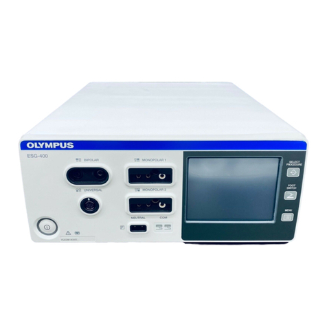
Olympus CelonLab ENT User manual

W7098046 (2014-08)
Celon
Lab
ENT
EN Instructions for Use 3
DE Ge rauchsanweisung 13
FR Mode d'emploi 23
IT Istruzioni d’uso 35
ES Instrucciones de uso 47
PT Manual de instruções 59
NL Ge ruiksaanwijzing 71
SV Bruksanvisning 83
FI Käyttöohje 93
DA Brugsanvisning 103
NO Bruksveiledning 113
EL Οδηγίες χρήσης 123


W7098046
3
Instructions for Use (English)
CelonLab
ENT
RFITT
po er control unit
REF: WB991007 (100 ... 120 V~)
REF: WB991001 (200 ... 240 V~)
1. Safety and Warnings
2. Description
2.1 Indications for Use
2.2 Contraindications
2.3 Features of the Unit
2.4 Description of the Controls
3. Installation Instructions
3.1 Po er Supply Connection
3.2 Equipotential Bonding
3.3 Moisture Protection
3.4 Commissioning
4. Instructions for Use
5. Cleaning and Disinfection
6. Maintenance and Repair
6.1 Changing the Po er Fuses
6.2 Repairs
6.3 Safety Checks
6.4 Disposal of the Unit
7. Technical Data
8. Legal Information
9. Sym ols
10. Manufacturer

CelonLab
ENT
EN Instructions for Use
4
W7098046
1. Safety and Warnings
Warning: The safety and effectiveness of electrosurgical
interventions depend not only on the design of the equipment used,
ut also to a major extent on factors which are under the control of
the user. It is therefore extremely important to read, understand and
follow the instructions supplied with the coagulation electrodes, the
power control unit and the accessories in order to ensure safety and
effectiveness.
Caution: The safety of electrosurgery ill be greatly enhanced by a thorough
kno ledge of the medical literature on the subject. Study of specific
information on the hazards and complications of the procedure in question is
especially recommended.
Caution: The CelonLab
ENT
po er control unit may only be used ith
compatible coagulation electrodes and accessories. The electrodes must be
designed for the maximum peak output voltage. (see Technical Data).
Caution: Before use, the electrosurgical unit and accessories must be
examined for damage. Cables and accessories ith damaged insulation or
connections must not be used.
Caution: Wherever possible, the patient should not be able to come into
contact ith electrically conductive components that are earthed. Route all
connecting cables, in particular the cables to the coagulation electrodes, so
that they are not in direct contact ith the patient or other cables.
Warning: The high frequency equipment, when applied to a patient
with a cardiac pacemaker, an implanted cardioverter defi rillator
(ICD) or other implanted electronic devices (IED), may cause
malfunctioning or failure of the implanted electronic device and may
seriously affect the patient. Always confirm that it is safe to proceed
with a cardiologist or the manufacturer of the implanted electronic
device efore proceeding. If monopolar modes of the electrosurgical
generator are used, position the neutral electrode so that the current
pathway does not pass through or near the implanted electronic
device and its lead system. The risk of malfunction or failure of an
implanted electronic device is reduced y the use of a ipolar mode.
A risk does exist, however, if the application is in close proximity to
the implanted electronic device.
Warning: The risk of flamma le gases or other materials eing
ignited exists with any surgical application of electrical energy.
Precautionary measures must e taken to keep flamma le materials
and su stances away from the site of intervention (do not use
flamma le anaesthetics, nitrous oxide or oxygen). Flamma le agents
used for cleaning and disinfection must e allowed to evaporate
efore the electrosurgical unit is used.
Caution: Electrodes and probes of monitoring, stimulation and imaging
devices can conduct radiofrequency currents. Electrodes and probes (e.g. ECG
and EEG) must be kept as far a ay as possible from the site of the
electrosurgical intervention. Needle monitoring electrodes should not be used,
as they may cause patient burns. Physiological monitoring equipment
incorporating high frequency current limiting devices is recommended.

Instructions for Use EN CelonLab
ENT
W7098046
5
Caution: The CelonLab
ENT
po er control unit complies ith the EMC
(electromagnetic compatibility) standard. Nevertheless, hen the po er
control unit is active it may disturb neighbouring electronic equipment. Please
follo the instructions in the technical documentation regarding
electromagnetic ambient conditions (“EMC Guidelines”).
Caution: Mobile communication equipment (e.g. mobile phones) may disturb
the functioning of the po er control unit and other electrical medical
equipment.
Caution: Contact ith the tip of the coagulation electrodes may cause burns
hen the po er control unit is active.
Caution: In the event of a defect or malfunction in the unit, an undesirably
high output po er may be emitted.
Caution: When the housing is opened there is a danger of electric shock. The
unit must only be serviced by authorised technicians.
Caution: Federal La of the USA restricts this device to use by or on the
order of a physician.
2. Description
2.1 Indications for Use
The system, comprising the CelonLab
ENT
and compatible coagulation
electrodes, is indicated for ablation and coagulation of soft tissue in
otorhinolaryngology (ENT) surgery. This method of treatment is also referred to
as bipolar radiofrequency induced thermotherapy (RFITT).
2.2 Contraindications
Electrosurgical interventions are contraindicated if, in the judgment of the
physician, tissue coagulation could have a negative effect on the state of the
patient. Radiofrequency induced coagulation may be contraindicated for patients
ith a eakened immune system.
2.3 Features of the Unit
The CelonLab
ENT
po er control unit supplies the compatible bipolar
coagulation electrodes via its bipolar output. A neutral electrode (return
electrode) is not necessary.
The po er control unit features clearly laid out controls. After s itching on the
unit, the user only has to select the po er level and activate the po er output
using the foots itch.
The po er control unit provides an acoustic output of the coagulation status.
With CelonLab
ENT,
the “generator active” signal, hich usually has a fixed
frequency ith conventional radiofrequency generators, is designed so that its
frequency is proportional to the tissue resistance at any particular moment. This
permits acoustic monitoring of the coagulation status, since the latter is directly
connected ith the tissue resistance. If the resistance increases beyond a
specific limit value, hich means that the coagulation process has ended, this is
indicated by the tone being pulsed.

CelonLab
ENT
EN Instructions for Use
6
W7098046
2.4 Description of the Controls
Fig. 2.1: Front panel of the RFITT po er control unit CelonLab
ENT
Fig. 2.2: Back of the RFITT po er control unit CelonLab
ENT

Instructions for Use EN CelonLab
ENT
W7098046
7
1Power switch: The po er s itch is for s itching the unit on and off.
When the po er control unit is s itched on the po er s itch glo s green.
For safety reasons the unit is only ready for use after approx. 10 seconds.
The po er setting is al ays at its minimal value of 1 after s itching on.
2Connection sockets for RFITT coagulation electrodes: All compatible
bipolar coagulation electrodes can be connected to this socket.
3Connection socket for the foot switch: The CelonFoot
S itch
can be
connected to this socket. When the foots itch is pressed, po er output is
activated. The generator cannot be operated ithout a foots itch
connected.
4Signal lamp: “Power output”: If the control unit is activated by pressing
the foots itch, and if po er can be emitted at the output, this is indicated
by this blue lamp.
5Signal lamp: “resistance too low”: This red lamp illuminates, in
combination ith an acoustic signal (intermittent tone), to indicate that the
resistance is lo er than 30 ohms. Possible cause: short circuit in the
electrode or cable. For safety reasons the po er output is automatically
s itched off.
6Power display: This t o-digit LED display indicates the chosen po er
setting (values bet een 1 and 25). The indicated value does not necessarily
correspond to the emitted po er in atts because the po er depends on
the tissue resistance.
7Button for increasing the power setting: Pressing this button increases
the po er level by 1.
8Button for reducing the power setting: Pressing this button decreases
the po er level by 1.
9Sym ol: “Unit is defi rillator-safe”: The use of a defibrillator ill not
cause any damage to the unit, provided that the po er control unit is not
active, i.e. the foots itch is not pressed.
10 Sym ol: “Caution! Read the Instructions for Use”: If a unit carries
this symbol, it is necessary to read the Instructions for Use before using it
for the first time.
11 Connection for equipotential onding: See Chap. 3.2 (Installation
Instructions)
12 Power connection: This socket is used for connecting the unit to the
po er supply system. (see Chap. 3.1)
13 Holder for power fuses: The po er control unit is protected by t o
external fuses (see Chap. 6.1). If these fuses blo , an authorised technician
should check the unit for possible defects before ne fuses are fitted and
the unit is operated again.
14 Rating plate: Details of the manufacturer, supply voltage, maximum
po er input, moisture protection class (IP), serial number and relevant
output data.
15 Volume switch: This s itch is used for setting the volume of the acoustic
signal to loud or quiet. In the standard setting (s itch not pressed) the
signal is loud. The sound can be decreased by pressing the s itch.
16 Sym ol: “Non-ionising radiation”: Units hich carry this symbol emit
radiofrequency energy for diagnostic or therapeutic purposes.

CelonLab
ENT
EN Instructions for Use
8
W7098046
3. Installation Instructions
The unit must be properly installed and commissioned by Olympus Winter & Ibe
GmbH or by a person or firm (distributor) commissioned and authorised by
Olympus Winter & Ibe GmbH.
3.1 Power Supply Connection
The unit must only be connected to the po er supply system ith the cable
supplied or a cable of the same quality (see Chapter 7
Technical Data
). The
po er socket must be correctly installed and must have an earthing contact.
Before connecting up to the po er supply, check that the supply voltage agrees
ith the electrical data on the po er supply unit’s rating plate.
3.2 Equipotential Bonding
To increase electrical safety, the unit can be connected to the equipotential
bonding system of the treatment room. (The housings of all equipment that
comes into contact ith the patient are electrically connected in order to prevent
lo -frequency electrical currents endangering the patient in the event of a
defect in the conventional protective conductor system.)
3.3 Moisture Protection
The unit’s housing is drip-proof (IP 21). Nevertheless, no containers containing
liquid should be placed on the unit.
The CelonFoot
S itch
is atertight (IP 68). If it comes into contact ith liquid
there is no risk of short circuit.
3.4 Commissioning
Before any unit is used for the first time, the follo ing functional test must be
carried out:
1. Connect to the po er supply and equipotential bonding (see above).
2. Connect the foots itch to the socket (3).
3. S itch on the control unit at the po er s itch (1); the green pilot lamp
must glo .
4. Set the maximum coagulation po er ith buttons (7) and (8) up to the
maximal value of 25. Check that the po er display (6) sho s all values
bet een 1 and 25 correctly.
5. Press the foots itch: The blue signal lamp (4) must no glo , an acoustic
signal (intermittent tone) must be audible.
6. Release the foots itch.
7. End of commissioning.

Instructions for Use EN CelonLab
ENT
W7098046
9
4. Instructions for Use
Caution: The po er control unit is intended for use by qualified medical
personnel trained in the use of electrosurgical equipment and targeted
puncture of areas of organs. Please also observe Section 1 (Safety and
Warnings) and also the Instructions for Use for the coagulation electrodes and
accessories.
1. Connect the foot s itch to the socket (3).
2. S itch on the control unit at the po er s itch (1). The unit is ready for
operation after approx. 10 seconds.
3. Connect an RFITT
coagulation electrode to the socket (2).
4. Set the necessary coagulation po er ith buttons (7) and (8) in the range
bet een 1 and 25. The po er depends on the type of treatment in
question. Suggestions for suitable settings are to be found in the
Instructions for Use of the compatible coagulation electrodes.
5. Insert the coagulation electrode into the tissue area to be treated.
6. Activate the po er output by pressing the foots itch (the foots itch must
be held do n throughout the entire treatment).
7. End the application by releasing the foots itch hen the end of treatment
(dehydration of the tissue) is indicated by a pulsed acoustic signal or at
any time during the treatment.
8. Repeat steps 4 to 7 if required by the therapy.
9. S itch off the unit at the po er s itch (1).
10. Clean the components follo ing the instructions in Section 5.
Caution: When using bipolar radiofrequency induced thermotherapy (RFITT),
a lo er po er level may lead to longer application times and therefore a larger
coagulation volume.
5. Cleaning and Disinfection
All surfaces of the unit’s housing can be cleaned and disinfected ith the
cleaning agents and surface disinfectants normally used for medical equipment
(mild cleaning solution, e.g. 70 % isopropyl alcohol). No liquid must enter the
connector or the unit during cleaning.
The CelonFoot
S itch
can be spray or ipe disinfected ith the products
mentioned above.
6. Maintenance and Repair
6.1 Changing the Power Fuses
The unit is protected by t o po er fuses accessible from the outside. If these
fuses blo , an authorised technician should check the unit for possible defects
before ne fuses are fitted and the unit is operated again, as overloading of the
fuses is usually the result of a defect.
Caution: Disconnect the po er plug before changing the fuses! The fuses
inside the housing must only be changed by an authorised technician.

CelonLab
ENT
EN Instructions for Use
10
W7098046
6.2 Repairs
If a defect occurs, Olympus Winter & Ibe GmbH or a contact appointed by
Olympus Winter & Ibe GmbH (e.g. distributor) must be informed. The repair
must only be carried out by Olympus Winter & Ibe GmbH or a firm authorised by
Olympus Winter & Ibe GmbH (ask the Olympus Winter & Ibe GmbH distributor
responsible for your area). Service documents such as circuit diagrams, parts
lists, equipment descriptions and setting instructions are available from the
manufacturer for technicians ho are authorised to carry out maintenance and
repair.
Caution: When the housing is opened there is a danger of electric shock. The
unit must only be opened by authorised technicians.
6.3 Safety Checks
The unit must undergo a safety check at yearly intervals in accordance ith the
national statutory regulations. For this purpose, Olympus Winter & Ibe GmbH or
a firm authorised by Olympus Winter & Ibe GmbH must be commissioned by the
operator.
6.4 Disposal of the Unit
When disposing of the product, or any of its components, follo all applicable
national and local la s and guidelines.
Waste Electrical and Electronic Equipment
In accordance ith European Directive 2002/96/EC on Waste Electrical
and Electronic Equipment, this symbol indicates that the product must
not be disposed of as unsorted municipal aste, but should be
collected separately.
Refer to your local Olympus distributor for return and/or collection systems
available in your country.
7. Technical Data
Unit designation CelonLab
ENT
po er control unit
REF: WB991007 (100 ... 120 V~)
REF: WB991001 (200 ... 240 V~)
Outputs bipolar
Applied part Type BF, defibrillation-safe
Rated output po er 25 W at 100 Ohm
Po er selection From 1 to 25 W in 1 W steps
Impedance dependency of the po er See information accompanying the unit
Rated output frequency 470 kHz
Max. peak output voltage < 150 V
peak
Max. peak output voltage as a function
of the po er level
See information accompanying the unit
Audio-frequency of “generator active”
signal 300 Hz – 2.5 kHz (for impedance range
25 – 400 ohms)
Audio-frequency if impedance too lo 300 Hz, pulsed ith approx. 1 Hz

Instructions for Use EN CelonLab
ENT
W7098046
11
Audio-frequency if impedance too high ≈ 2.5 kHz, pulsed ith approx. 1 Hz
Rated supply voltage 100 … 120 V~
200 ... 240 V~
Rated supply frequency 50 … 60 Hz
Po er input at max. po er 95 VA
Po er fuses (2 x) 1.6 A T-lag, 250 V, 5x20 mm, UL/CSA
REF: WB991007 (100 ... 120 V~)
0.8 A T-lag, 250 V, 5x20 mm, UL/CSA
REF: WB991001 (200 ... 240 V~)
Po er connection line IEC 60320-1/C13
Dimensions (W x H x D)
267 x 165 x 335 mm
Weight Unit: 7.3 kg
Foots itch: 1.0 kg
Protection class I
Classification according to Medical Devices
Directive: Europe / US (FDA)
IIb / II
Foreign body/moisture protection IP 21, foots itch IP 68
Transport conditions: Temperature
Relative humidity
-34 ... +65 °C
15 ... 80 %, non-condensing
Storage conditions: Temperature
Relative humidity
-25 ... +60 °C
15 ... 80 %, non-condensing
Operating conditions: Temperature
Relative humidity
+10 ... +40 °C
15 ... 80 %, non-condensing
Standards and directives applied:
93/42/EEC MDD Conformity assessment
EN ISO 13485 Quality assurance systems – Medical Devices –
Specific requirements for application as per ISO 9001
EN 60601-1 Medical electrical devices
EN 60601-1-2 Medical electrical devices (EMC)
EN 60601-2-2 Medical electrical devices (electrosurgical devices)
EN ISO 14971 Medical devices risk analysis

CelonLab
ENT
EN Instructions for Use
12
W7098046
8. Legal Information
Improper handling releases the manufacturer from its arranty obligation. In
particular, these Instructions for Use must be follo ed.
Liability for products that have been modified from the original, misused or
improperly used, is excluded.
RFITT is a registered trademark of Olympus Winter & Ibe GmbH.
Federal La of the USA restricts this device to use by or on the order of a
physician.
9. Sym ols
Manufacturer Observe Instructions
for Use
Date of manufacture
Store in a dry place
Reference number
Temperature range for
storage (during transport)
Serial number
15-80 %
(15-80 %)
RH
Relative humidity for
storage (during transport)
Quantity Product carries the CE mark
Observe Instructions
for Use
10. Manufacturer
Olympus Winter & I e Gm H
Kuehnstr. 61
22045 Hamburg
GERMANY
Tel: +49-40-66966-0
Fax:
+49
-
40
-
66966
-
2109
E
-
mail:
info@olympus-oste.eu
Internet:
.olympus
-
oste.eu
Olympus Wint
er & Ibe GmbH
is a certified company in accordance ith ISO
9001 and EN ISO 13485.
-
25 °C
(-34 °C)
(+65 °C)
+60 °C

W7098046
13
Ge rauchsanweisung (Deutsch)
CelonLab
ENT
RFITT-Leistungssteuergerät
REF: WB991007 (100 ... 120 V~)
REF: WB991001 (200 ... 240 V~)
1. Sicherheits- und Warnhinweise
2. Beschrei ung
2.1 Ver endungsz eck
2.2 Kontraindikationen
2.3 Gerätemerkmale
2.4 Beschreibung der Bedienelemente
3. Installationshinweise
3.1 Netzanschluss
3.2 Potentialausgleich
3.3 Feuchtigkeitsschutz
3.4 Erstinbetriebnahme
4. Hinweise zum Ge rauch
5. Reinigung und Desinfektion
6. Wartung und Instandhaltung
6.1 Aus echseln der Netzsicherungen
6.2 Reparaturen
6.3 Sicherheitstechnische Kontrollen
6.4 Entsorgung des Gerätes
7. Technische Daten
8. Rechtliche Hinweise
9. Sym ole
10. Hersteller

CelonLab
ENT
DE Gebrauchsan eisung
14
W7098046
1. Sicherheits- und Warnhinweise
Warnung: Die Sicherheit und Effektivität elektrochirurgischer
Eingriffe ist nicht nur von der Konstruktion der verwendeten Geräte
a hängig, sondern auch zu einem entscheidenden Teil von Faktoren,
die im Einfluss ereich des Anwenders liegen. Es ist daher von größter
Bedeutung, dass die Anleitungen der Koagulationselektroden, des
Leistungssteuergerätes sowie des Zu ehörs gelesen, verstanden und
eachtet werden, damit Sicherheit und Effektivität gewährleistet
sind.
Achtung: Umfassende Kenntnis der medizinischen Fachliteratur zu diesem
Thema erhöht die Sicherheit elektrochirurgischer Eingriffe erheblich.
Insbesondere ist das Studium einschlägiger Informationen zu den Gefahren
und Komplikationen des geplanten Eingriffes sehr zu empfehlen.
Achtung: Das Leistungssteuergerät CelonLab
ENT
darf ausschließlich mit
kompatiblen Koagulationselektroden und kompatiblem Zubehör eingesetzt
erden. Die Elektroden müssen für die maximale Spitzenausgangsspannung
ausgelegt sein (siehe Technische Daten).
Achtung: Vor der An endung ist die elektrochirurgische Einheit einschließlich
des Zubehörs auf Beschädigungen zu untersuchen. Kabel und Zubehör mit
beschädigter Isolierung oder beschädigten Anschlüssen dürfen nicht ver endet
erden.
Achtung: So eit möglich, sollte der Patient nicht in Kontakt mit geerdeten,
elektrisch leitenden Komponenten kommen können. Verlegen Sie alle
Verbindungskabel, insbesondere die Leitungen zu den Koagulationselektroden,
ohne direkten Patientenkontakt oder Kontakt zu anderen Kabeln.
Warnung: Die Anwendung des Hochfrequenzgeräts ei Patienten mit
einem Herzschrittmacher, einem implantierten Kardioverter-
Defi rillator (ICD) oder anderen implantierten elektronischen
Geräten (IED) kann zu Funktionsstörungen oder dem Ausfall des
implantierten elektronischen Geräts führen und den Patienten
ernsthaft gefährden. Versichern Sie sich vor dem Eingriff immer ei
einem Kardiologen oder dem Hersteller des implantierten
elektronischen Geräts, dass die Anwendung un edenklich ist. Bei
Einsatz von monopolaren Betrie sarten des elektrochirurgischen
Generators die Neutralelektrode so platzieren, dass der Strom nicht
durch das implantierte elektronische Gerät oder in seiner Nähe zw.
durch seine Elektroden oder in der Nähe von diesen verläuft. Bei
einer ipolaren Betrie sart ist die Gefahr einer Funktionsstörung
eines implantierten elektronischen Geräts und seines
A leitungssystems geringer. Bei Anwendung in unmittel arer Nähe
des implantierten elektronischen Geräts esteht diese Gefahr jedoch
e enfalls.
Warnung: Die Gefahr der Entzündung von entflamm aren Gasen oder
anderen Materialien esteht generell ei der chirurgischen
Anwendung von elektrischer Energie. Es müssen
Vorsichtsmaßnahmen getroffen werden, um entflamm are
Materialien und Su stanzen vom Eingriffs ereich fernzuhalten (keine
entflamm aren Narkosemittel und Lachgas zw. Sauerstoff
verwenden). Entflamm are Reinigungs- und Desinfektionsmittel
müssen vor Ge rauch des Elektrochirurgiegeräts verdampfen.

Gebrauchsan eisung DE CelonLab
ENT
W7098046
15
Achtung: Elektroden und Sonden von Über achungs-, Stimulations- oder
Bildgebungsgeräten können Hochfrequenzströme leiten. Elektroden und
Sonden (z. B. ECG, EEG) sind möglichst eit eg vom elektrochirurgischen
Eingriffsbereich anzuordnen. Nadelüber achungselektroden sollten nicht
ver endet erden, da sie beim Patienten Verbrennungen verursachen können.
Es ird empfohlen, Über achungsgeräte mit Hochfrequenz-
Schutzvorrichtungen zu ver enden.
Achtung: Das Leistungssteuergerät CelonLab
ENT
erfüllt die EMV-Norm
(elektromagnetische Verträglichkeit). Trotzdem können bei aktiviertem
Leistungssteuergerät benachbarte elektronische Geräte gestört erden. Bitte
beachten Sie die Hin eise in der technischen Dokumentation zu den
elektromagnetischen Umgebungsbedingungen („EMC Guidelines“).
Achtung: Mobile Kommunikationseinrichtungen (z.
B. Mobiltelefone) können
die Funktion des Leistungssteuergerätes und anderer medizinischer elektrischer
Geräte stören.
Achtung: Das Berühren der Spitze der Koagulationselektroden kann zu
Verbrennungen führen, enn das Leistungssteuergerät aktiviert ist.
Achtung: Bei einem Defekt oder einer Fehlfunktion des Gerätes kann eine
uner ünscht hohe Ausgangsleistung abgegeben erden.
Achtung: Beim Öffnen des Gehäuses besteht Stromschlaggefahr. Das Gerät
darf nur durch autorisierte Techniker ge artet erden.
Achtung: Gemäß der Bundesgesetzgebung der USA darf dieses
Medizinprodukt nur von Ärzten oder unter ärztlicher Aufsicht ver endet
erden.
2. Beschrei ung
2.1 Verwendungszweck
Das System, bestehend aus dem CelonLab
ENT
und den kompatiblen
Koagulationselektroden, dient zur Ablation und Koagulation von eichem
Ge ebe in der Hals-Nasen-Ohren-Heilkunde (HNO, englisch ENT). Diese
Behandlungsmethode ird auch bipolare Radiofrequenz-induzierte
Thermotherapie (RFITT) genannt.
2.2 Kontraindikationen
Elektrochirurgische Eingriffe sind kontraindiziert, falls sich entsprechend der
Beurteilung des Arztes die Ge ebekoagulation negativ auf den Zustand des
Patienten aus irken könnte. Bei Patienten mit gesch ächtem Immunsystem
kann die radiofrequenzinduzierte Ge ebekoagulation kontraindiziert sein.
2.3 Gerätemerkmale
Das Leistungssteuergerät CelonLab
ENT
versorgt über seinen bipolaren Ausgang
die kompatiblen bipolaren Koagulationselektroden. Eine Neutralelektrode
(Rückleitelektrode) ist nicht not endig.
Das Leistungssteuergerät zeichnet sich durch eine übersichtliche Anordnung der
Bedienelemente aus. Nach dem Einschalten des Gerätes ist vom An ender
lediglich die Leistungsstufe zu ählen und die Leistungsabgabe mit dem
Fußschalter zu aktivieren.

CelonLab
ENT
DE Gebrauchsan eisung
16
W7098046
Das Leistungssteuergerät besitzt eine akustische Ausgabe des
Koagulationsstatus. Der bei konventionellen Hochfrequenz-Generatoren
üblicher eise festfrequente Signalton „Generator aktiv“ ist beim CelonLab
ENT
so ausgelegt, dass seine Frequenz proportional zum momentanen
Ge ebe iderstand ist. Das ermöglicht die akustische Über achung des
Koagulationsstatus, da dieser in direktem Zusammenhang mit dem
Ge ebe iderstand steht. Steigt der Widerstand über einen bestimmten
Grenz ert, as bedeutet, dass der Koagulationsprozess beendet ist, ird dies
durch ein Takten des Tones angezeigt.
2.4 Beschrei ung der Bedienelemente
Abb. 2.1: Frontseite des RFITT-Leistungssteuergerätes CelonLab
ENT

Gebrauchsan eisung DE CelonLab
ENT
W7098046
17
Abb. 2.2: Rückseite des RFITT- Leistungssteuergerätes CelonLab
ENT
1Netzschalter: Der Netzschalter dient zum Ein- und Ausschalten des
Gerätes. Der eingeschaltete Zustand des Leistungssteuergerätes ird durch
das grüne Aufleuchten des Netzschalters signalisiert. Aus
Sicherheitsgründen ist das Gerät erst ungefähr 10 Sekunden nach dem
Einschalten betriebsbereit. Nach dem Einschalten befindet sich die
Leistungseinstellung immer auf ihrem Minimal ert von 1.
2Anschluss uchsen für RFITT-Koagulationselektroden: Alle
kompatiblen bipolaren Koagulationselektroden können an dieser Buchse
angeschlossen erden.
3Anschluss uchse für Fußschalter: An dieser Buchse kann der
Fußschalter CelonFoot
S itch
angeschlossen erden. Bei Betätigung des
Fußschalters ird die Leistungsabgabe aktiviert. Ohne Anschluss eines
Fußschalters lässt sich der Generator nicht in Betrieb nehmen.
4Signallampe „Leistungsa ga e“: Wird durch die Betätigung des
Fußschalters das Steuergerät aktiviert und kann Leistung am Ausgang
abgegeben erden, ird dies durch das Aufleuchten dieser blauen Lampe
signalisiert.
5Signallampe „zu niedriger Widerstand“: Das Aufleuchten dieser roten
Lampe signalisiert in Kombination mit einem akustischen Signal
(unterbrochener Ton), dass der Widerstand niedriger als 30 Ohm ist.
Mögliche Ursache: Kurzschluss in Elektrode oder Kabel. Aus
Sicherheitsgründen ird die Leistungsabgabe automatisch abgeschaltet.
6Leistungsanzeige: Dieses z eistellige LED-Display zeigt die ausge ählte
Leistungseinstellung (Werte z ischen 1 und 25) an. Der angezeigte Wert
entspricht nicht not endiger Weise der abgegebenen Leistung in Watt
aufgrund der Abhängigkeit der Leistung vom Ge ebe iderstand.
7Taste zum Erhöhen der Leistungseinstellung: Durch Drücken dieser
Taste ird die Leistungsstufe um 1 erhöht.

CelonLab
ENT
DE Gebrauchsan eisung
18
W7098046
8Taste zum Verringern der Leistungseinstellung: Durch Drücken dieser
Taste ird die Leistungsstufe um 1 verringert.
9Sym ol „Gerät ist defi rillatorsicher“: Bei Einsatz eines Defibrillators
nimmt das Gerät keinen Schaden. Voraussetzung ist, dass das
Leistungssteuergerät nicht aktiv ist, d.
h. der Fußschalter nicht betätigt ird.
10 Sym ol „Achtung! Ge rauchsanweisung lesen!“: Ist ein Gerät mit
diesem Zeichen versehen, ist es not endig, vor der erstmaligen Benutzung
die Gebrauchsan eisung zu lesen.
11 Anschluss für Potentialausgleich: Siehe Kap. 3.2 (Installations-
hin eise).
12 Netzanschluss: Diese Buchse dient dem Anschluss an das
Stromversorgungsnetz (siehe Kap. 3.1)
13 Halter für Netzsicherungen: Das Leistungssteuergerät ird mit z ei
externen Sicherungen abgesichert (siehe Kap. 6.1). Falls diese Sicherungen
durchschmelzen, sollte vor dem Einsetzen neuer Sicherungen und der
Wiederinbetriebnahme des Gerätes ein dazu autorisierter Techniker das
Gerät auf mögliche Fehler untersuchen.
14 Geräte-Typenschild: Angabe des Herstellers, der Versorgungsspannung,
der maximal aufgenommenen Leistung, der Feuchtigkeitsklasse (IP), der
Seriennummer und relevanter Ausgangsdaten.
15 Lautstärkeschalter: Mit diesem Schalter kann der Signalton ahl eise
laut oder leise gestellt erden. Bei der Standardeinstellung (Schalter nicht
gedrückt) ist der Ton laut. Durch Drücken des Schalters kann die Lautstärke
verringert erden.
16 Sym ol „Nichtionisierende Strahlung“: Geräte, die mit diesem Zeichen
versehen sind, geben Hochfrequenzenergie für diagnostische oder
therapeutische Z ecke ab.
3. Installationshinweise
Die Installation und die Erstinbetriebnahme des Gerätes ist sachgemäß von der
Olympus Winter & Ibe GmbH oder von einer durch sie beauftragten und
berechtigten Person oder Firma (Vertrieb) durchzuführen.
3.1 Netzanschluss
Das Gerät darf an das Stromversorgungsnetz nur mit dem mitgelieferten oder
einem gleich ertigen Kabel (siehe Kap. 7
Technische Daten
) angeschlossen
erden. Die Steckdose muss ein andfrei installiert sein und einen Schutzkontakt
besitzen. Vor dem Netzanschluss ist die Übereinstimmung der Spannung des
Stromversorgungsnetzes mit der Angabe auf dem Typenschild des
Leistungssteuergerätes zu überprüfen.
3.2 Potentialausgleich
Zur Erhöhung der elektrischen Sicherheit kann das Gerät an das
Potentialausgleichssystem des Behandlungsraumes angeschlossen erden. (Die
Gehäuse aller mit dem Patienten in Kontakt kommenden Geräte erden
elektrisch verbunden, um auch bei einem Defekt des konventionellen
Schutzleitersystems zu verhindern, dass niederfrequente elektrische Ströme den
Patienten gefährden.)

Gebrauchsan eisung DE CelonLab
ENT
W7098046
19
3.3 Feuchtigkeitsschutz
Das Gehäuse des Gerätes ist tropf assergeschützt (IP 21). Trotzdem sollten
keine Behälter mit Flüssigkeit auf das Gerät gestellt erden.
Der Fußschalter CelonFoot
S itch
ist asserdicht (IP 68). Kommt dieser mit
Flüssigkeit in Verbindung, besteht keine Kurzschlussgefahr.
3.4 Erstin etrie nahme
Bei jedem Gerät muß vor dem Erstgebrauch der folgende Funktionstest
durchgeführt erden:
1. Netzanschluss und Potentialausgleich (s. o.) herstellen.
2. Anschließen des Fußschalters an Buchse (3).
3. Einschalten des Steuergerätes mit Netzschalter (1); die grüne Kontrollampe
muss leuchten.
4. Einstellen der maximalen Koagulationsleistung mit den Tasten (7) und (8)
auf den Maximal ert 25. Überprüfen, ob die Leistungsanzeige (6) alle
Werte z ischen 1 und 25 korrekt anzeigt.
5. Betätigen des Fußschalters: Die blaue Signallampe (4) muss jetzt leuchten,
ein akustisches Signal (Intervallton) muss hörbar sein.
6. Loslassen des Fußschalters.
7. Ende der Inbetriebnahme.
4. Hinweise zum Ge rauch
Achtung: Das Leistungssteuergerät ist für den Gebrauch durch qualifiziertes
medizinisches Personal bestimmt, das in der Ver endung von
elektrochirurgischen Systemen und für die gezielte Punktion von
Organbereichen ausgebildet urde. Bitte beachten Sie außerdem Abschnitt 1
(Sicherheits- und Warnhin eise) so ie die Gebrauchsan eisungen der
Koagulationselektroden und des Zubehörs.
1. Anschließen des Fußschalters an Buchse (3).
2. Einschalten des Steuergerätes mit dem Netzschalter (1). Das Gerät ist nach
ca. 10 Sekunden betriebsbereit.
3. Anschließen einer RFITT-Koagulationselektrode an der Buchse (2).
4. Einstellen der not endigen Koagulationsleistung mit den Tasten (7) und (8)
im Bereich z ischen 1 und 25. Die Leistung hängt von der je eiligen
Behandlungsart ab. Vorschläge für geeignete Einstellungen befinden sich in
den Gebrauchsan eisungen der kompatiblen Koagulationselektroden.
5. Einstechen der Koagulationselektrode in das zu behandelnde Ge ebeareal.
6. Aktivieren der Leistungsabgabe durch Betätigen des Fußschalters (Der
Fußschalter muss ährend der gesamten Therapiedauer gedrückt gehalten
erden).
7. Beenden der Applikation durch Loslassen des Fußschalters, enn das Ende
der Therapie (Dehydrierung des Ge ebes) durch ein getaktetes akustisches
Signal angezeigt ird oder zu jeder Zeit ährend der Therapie.
8. Wiederholen der Punkte 4 bis 7, falls dies für die Therapie erforderlich ist.
9. Ausschalten des Gerätes mit dem Netzschalter (1).
10. Reinigung der Komponenten entsprechend den An eisungen in Abschnitt 5.

CelonLab
ENT
DE Gebrauchsan eisung
20
W7098046
Achtung: Beim Einsatz der bipolaren Radiofrequenz-induzierten
Thermotherapie (RFITT) kann eine kleinere Leistungsstufe zu längeren
Applikationszeiten und somit zu einem größeren Koagulationsvolumen führen.
5. Reinigung und Desinfektion
Das Gehäuse des Gerätes kann auf allen Außenflächen mit den in der Medizin
üblichen Reinigungs- und Flächendesinfektionsmitteln (milde Reinigungs-
lösungen, z.
B. 70 %-iger Isopropylalkohol) gereinigt und desinfiziert erden.
Bei der Reinigung darf keine Flüssigkeit in die Steckverbinder oder in das Gerät
gelangen.
Der Fußschalter CelonFoot
S itch
kann mit den oben genannten Mitteln sprüh-
oder ischdesinfiziert erden.
6. Wartung und Instandhaltung
6.1 Auswechseln der Netzsicherungen
Das Gerät ird mit z ei von außen zugänglichen Netzsicherungen abgesichert.
Falls diese Sicherungen durchschmelzen, sollte vor dem Einsetzen neuer
Sicherungen und der Inbetriebnahme ein dazu autorisierter Techniker das Gerät
auf mögliche Fehler untersuchen, da eine Überlastung der Sicherungen meistens
die Folge eines Fehlers ist.
Achtung: Vor dem Aus echseln der Sicherungen ist der Netzstecker zu
ziehen! Die Sicherungen innerhalb des Gehäuses dürfen nur durch einen
autorisierten Techniker ausgetauscht erden.
6.2 Reparaturen
Tritt ein Defekt auf, ist die Olympus Winter & Ibe GmbH oder ein von ihr
genannter Ansprechpartner (z.
B. Vertrieb) zu benachrichtigen. Die
Instandsetzung darf nur von der Olympus Winter & Ibe GmbH oder von einer
durch sie autorisierten Firma (fragen Sie den für Ihren Bereich zuständigen
Vertriebspartner der Olympus Winter & Ibe GmbH) durchgeführt erden.
Serviceunterlagen ie Schaltpläne, Ersatzteillisten, Gerätebeschreibungen und
Einstellan eisungen sind für zur Wartung und Reparatur des Gerätes
autorisierte Techniker beim Hersteller erhältlich.
Achtung: Beim Öffnen des Gehäuses besteht Stromschlaggefahr. Das Gerät
darf nur durch autorisierte Techniker geöffnet erden.
6.3 Sicherheitstechnische Kontrollen
Das Gerät ist entsprechend den nationalen gesetzlichen Vorschriften in
jährlichen Abständen einer sicherheitstechnischen Kontrolle zu unterziehen.
Hierfür ist vom Betreiber die Olympus Winter & Ibe GmbH oder eine von der
Olympus Winter & Ibe GmbH autorisierte Firma zu beauftragen.
6.4 Entsorgung des Gerätes
Wenn Sie das Produkt oder dessen Bestandteile entsorgen, halten Sie alle
geltenden staatlichen und lokalen Gesetze und Richtlinien ein.
Elektro- und Elektronik-Altgeräte
Other manuals for CelonLab ENT
1
Table of contents
Languages:
Other Olympus Inverter manuals