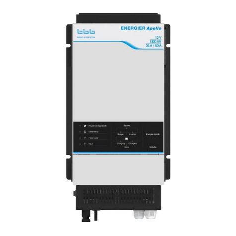
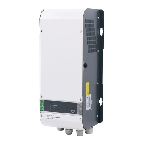
TBB power Raython Series User manual

Raython series
All-in-one Standalone Solar Power System
Off Grid
For Outdoor Use
USER MANUAL
Version 1.0
Date: DEC. 2021

A
Ab
bo
ou
ut
t
T
TB
BB
B
TBB Power is a dedicated designer and manufacturer of sophisticated and environmentally
rugged power electronic equipment.
We are offering a wide range of power conversion product from battery charger, standalone
inverter, inverter charger combination and solar charge controller.
We ensure consistent product quality by subjecting every product to strictly choice of superior
quality components, rigorous testing and burn-in throughout the production process. TBB
Power is certified by TUV in accordance with ISO9001 and can be your reliable power solution
provider.
D
Di
is
sc
cl
la
ai
im
me
er
r
Unless specially agreed in writing, TBB Power Co., Ltd
➢Take no warranty as to the accuracy, sufficiency of suitability of any technical or other
information provided in this manual or other documentation.
➢Assumes no responsibility or liability for loss or damage, whether direct, indirect,
consequential or incidental, which might arise out of the use of such information
➢TBB offer standard warranty with its products, taking no responsibility for direct or indirect
loss due to equipment failure.
A
Ab
bo
ou
ut
t
t
th
hi
is
s
M
Ma
an
nu
ua
al
l
This manual describes our product features and provides procedure of installations. This manual is
for anyone intending to install our equipment.

G
Ge
en
ne
er
ra
al
l
I
In
ns
st
tr
ru
uc
ct
ti
io
on
n
Thanks for choosing our products and this manual is suitable for RAYTHON series Solar
Intelligent Energy Storage system.
This chapter contains important safety and operation instructions. Read and keep this User
Guide well for later reference.
The RAYTHON series needs to be installed by professionals and please pay attention to the
following points prior to installation:
1> Please check the DC input voltage or battery voltage is the same to the nominal input voltage
of this inverter.
2> Please connect positive terminal “+” of the battery to “+” input of the inverter.
3> Please connect negative terminal “-” of the battery to “-” input of the inverter.
4> Please use the shortest cable to connect and ensure the secure connection.
5> While connecting, please secure the connection and avoid short cut between positive
terminal and negative terminal of the battery, to avoid damage to the battery.
6> The inverter will have high voltage inside. Only authorized electrician can open the case.
7> The inverter WAS NOT designed to use in any life retaining equipment.

I
In
nd
de
ex
x
1.0 General Safety Instruction ............................................................................................................................... - 4 -
1.1 Safety Instruction..............................................................................................................................- 4 -
1.2 Symbols Used in the Documentation.............................................................................................- 4 -
1.3 General Precaution ...........................................................................................................................- 4 -
1.4 Precaution Regarding Battery Operation......................................................................................- 5 -
2.0 System Description........................................................................................................................................... - 6 -
2.1 Raython Cabinet Dimensions .........................................................................................................- 7 -
2.2 Apollo Matrix Solar Hybrid Inverter .............................................................................................- 8 -
2.3 Kinergier Pro Inverter Charger.......................................................................................................- 9 -
2.4 Solar Mate MPPT Charge Controller .............................................................................................- 9 -
2.5 Kinergy Data Logging Stick ..........................................................................................................- 10 -
3.0 Functional Description................................................................................................................................... - 12 -
4.0 Installation ....................................................................................................................................................... - 13 -
4.1 Material List.....................................................................................................................................- 13 -
4.2 Location............................................................................................................................................- 13 -
4.3 Placement.........................................................................................................................................- 14 -
4.4 Fix the castor....................................................................................................................................- 15 -
4.4 Fix the Cabinet ................................................................................................................................- 15 -
4.5 Wiring Recommendation...............................................................................................................- 16 -
4.6 Connection Terminal Description ................................................................................................- 16 -
4.7 Wiring Instruction ..........................................................................................................................- 17 -
4.7.1 Connecting to Earth.............................................................................................................- 17 -
4.7.2 Connecting AC Grid Cable.................................................................................................- 18 -
4.7.3 Connecting the Loads..........................................................................................................- 19 -
4.7.4 Connecting PV in Cable......................................................................................................- 20 -
4.7.5 Connecting the AGS Terminal ...........................................................................................- 20 -
4.8 All Switches of the unit..................................................................................................................- 21 -
5.0 Operation......................................................................................................................................................... - 24 -
5.1 Double Checking ............................................................................................................................- 24 -
5.2 Switching on the Battery................................................................................................................- 24 -
5.3 Switch on the Inverter....................................................................................................................- 24 -
5.4 Power on PV....................................................................................................................................- 25 -
5.5 Power OFF .......................................................................................................................................- 26 -
5.6 Bypass Switch Application............................................................................................................- 26 -
5.7 Connect to the NOVA Monitoring Platform ...............................................................................- 27 -
6.0 Configuration .................................................................................................................................................. - 28 -
7.0 Specification .................................................................................................................................................... - 29 -

RAYTHON User Manual V1.0
1.0 General Safety Instruction
1.1 Safety Instruction
As dangerous voltages and high temperature exist within the RAYTHON, only qualified and
authorized maintenance personnel are permitted to open and repair it.
This manual contains information concerning the installation and operation of the RAYTHON. All
relevant parts of the manual should be read prior to commencing the installation. Please follow the
local stipulation meantime.
Any operation against safety requirement or against design, manufacture, safety standard, and are
out of the manufacturer warranty.
1.2 Symbols Used in the Documentation
This symbol indicates a hazardous situation which, if not avoided, could result in death
or serious injury.
This symbol indicates a situation which, if the instructions are not followed, could result
in injury and damage to the equipment.
This symbol indicates a situation which, if the instructions are not followed, could result
in damage to the equipment.
1.3 General Precaution
To avoid fire and electric shock,make sure all cables selected with right gauge and
being connected well. Smaller diameter and broken cable are not allowed to use. Please
do not put any inflammable goods near to RAYTHON.
Do not expose to dust, rain, snow or liquids of any type,it is designed for indoor use.
DO NOT block off ventilation, otherwise the RAYTHON would be overheating.

RAYTHON User Manual V1.0
1.4 Precaution Regarding Battery Operation
Only authorized and trained person who should be familiar to battery installation, preparation,
charging, and maintenance is permitted to the operation for battery.
SHOCK HAZARD- DO NOT touch the uninsulated battery connectors or terminals. Be sure to
discharge static electricity of tools and technicians by touching a grounded surface, but away from
the cells and flame arresters.
All tools should be adequately insulated to avoid the possibility of shorting connections.
DO NOT lay tools on the top of the battery.
Although the batteries are sealed and no gas emitted during normal operation, they contain
potentially explosive gases, which may be released under abnormal operating conditions, such as a
charger malfunction. It is the responsibility of the customer to provide adequate ventilation so that
hydrogen gas accumulation in battery area does not exceed 2% by volume. However, normal air
circulation in a ventilated facility will preclude any hydrogen build-up even during cyclic charging.
Never install batteries in a sealed cabinet or enclosure.
REMOVE all personal metal items such as rings, bracelets, necklaces, and watches while working
with batteries. Batteries can cause short-circuit current high enough to make metal melt, and could
cause severe burns.
The battery contains sulfuric acid, which may lead to the burning of the severe. In case of
skin touched the electrolyte, please remove contaminated clothing and flush affected
areas thoroughly with water. If eye contact has occurred, flush for a minimum of 15
minutes with large amounts of running water and seek for immediate medical attention.

RAYTHON User Manual V1.0
2.0 System Description
The Raython system is an all-in-one standalone solar power system. It is an ideal solution designed for
holiday houses or single-family houses that have no access to the grid power and the users often use
generators as their power supply. Featuring low pollution and low fuel consumption, it is also a perfect
solution for people who pursue a more sustainable lifestyle.
The Raython system is expertly assembled, tested and shipped as a complete system, integrating a solar
hybrid inverter or an inverter charger coupled with an MPPT solar charge controller, lithium battery
modules, wireless data logger, and AC and DC power distribution into one system. On arrival, Raython
system is ready to install and the all-in-one design makes it easy to install and saves your precious time.
Our Raython Solar System is designed for applications with a daily power use from 10kWh-20kWh, to
meet your different power need.
Features:
⚫All-in-one design for easy and quicker installation(<3 hours)
⚫Provided with IP54 protection index for outdoor use
⚫Factory assembled and tested system enable you get free from complicated groundwork
⚫ECO-friendly: lower pollution, less noise and lower fuel consumption
⚫AGS Function: automatically start and stop the generator according to the load level, battery
level or time period to ensure continuous power supply in the case of insufficient PV power or
system overload
⚫Leakage protect function on itsAC output to ensure safety
⚫Power assist function enables the Raython power system to discharge its batteries to power
heavy loads in conjunction with small generator, to prevent the overload on theAC Supply
⚫Strong ability to handle the spikes of the load initial current
⚫High performance system with strong overload capability, designed to power heavy loads like
air-conditioner, water pump, fridge, washing machine, etc.
⚫NOVA Web & App system monitoring, to display real-time data of all system components and
history record, to control the power generation and power consumption. According to historical
data, users can actively adjust and optimize power consumption habits

RAYTHON User Manual V1.0
2.1 Raython Cabinet Dimensions

RAYTHON User Manual V1.0
2.2 Apollo Matrix Solar Hybrid Inverter
Apollo Matrix is the new generation solar hybrid inverter designed for various types of off-grid
systems including the AC Couple system, DC Couple system, and generator hybrid system. It can
provide UPS class switching speed and support parallel as well as composing three-phase system.
Apollo Matrix delivers high reliability, performance, and industry-leading efficiency for
mission-critical application. Its distinguishing surge capability makes it capable to power most
demanding appliances, such as air conditioner, water pump, washing machine, freezer, etc.
With the function of power assist & power control, it can be used to work with a limited AC source
such as generator or limited grid. Apollo Matrix can automatically adjust its charging current to
avoid the grid or generator being overloaded. In case of temporary peak power appears, it can work
as the supplement source to the generator or grid.
For more information about Apollo Matrix, please refer to its manual.

RAYTHON User Manual V1.0
2.3 Kinergier Pro Inverter Charger
Kinergier Pro is the new generation inverter charger designed for various type of off grid system including AC
Coupled PV System, DC Coupled PV System and generator hybrid system. It can provide UPS class switching
speed and capability to support parallel as well as composing three phase system.
Kinergier Pro delivers high reliability, performance and industry leading efficiency for mission critical application.
Its distinguishing surge capability makes it capable to power most demanding appliances, such as air conditioner,
water pump, washing machine, freezer etc.
With the function of power assist & power control, it can be used to work with a limited AC source such as
generator or limited grid. Kinergier Pro can automatically adjust its charging current to avoid grid or generator to
be overloaded. In case of temporary peak power appears, it can work as a supplement source to generator or grid
For more information about Kinergier Pro, please refer to its manual.
2.4 Solar Mate MPPT Charge Controller
SP is a solar charge controller with built-in Maximum Power Point Tracking (MPPT) technology,
which can optimize the PV’s output eliminate the fluctuation due to shading or temperatures

RAYTHON User Manual V1.0
variables. It tracks the maximum power point of a PV array to deliver the maximum charging
current for battery, enabling PV array to increase the output by as much as 30% compared with
PWM design.
SP is a multi-voltage MPPT with built-in sophisticated battery charging algorithm for various kinds
of lead acid batteries, including AGM, GEL, Traction. Data management with a year of history
record was offered as well. Meantime, version for Lead-Carbon battery and lithium ion battery were
available upon request.
For more information about Solar Mate, please refer to its manual.
2.5 Kinergy Data Logging Stick
Available with GPRS and WIFI version, wireless data logger is an external communication device
connected to the TBB inverter through DB9 interface. Through NOVA web or APP, it offers a
convenient way to monitor the system performance remotely.
One Kinergy module can monitor up to 6 inverters, 6 Solar Mate MPPT solar charge controller and
2 IG PV inverter at the same time. It is widely applied with most inverter series of TBB Power, such
as Kinergier Pro, Apollo maxx, Apollo Matrix, RiiO and RiiO Sun.

RAYTHON User Manual V1.0
For more information about Kinergy, please refer to its manual.

RAYTHON User Manual V1.0
3.0 Functional Description
Raython is composed of Inverter, MPPT charge Controller, Kinergy, and Li-ion battery modules. As
following diagram shows, through monitoring the real-time output power, energy consumption of
the connected appliances and the battery SOC, Raython will automatically change the work mode
to keep your loads being powered.

RAYTHON User Manual V1.0
4.0 Installation
Prior to Installation
➢Read the manual carefully and confirm the voltage and current input requirements of the
load(s) are compatible with the unit’s output.
➢Also see the line voltage and current is compatible with the unit’s input requirements.
➢Wiring should be done to meet local electrical codes.
Use proper lifting techniques when lifting installing or moving the unit.
4.1 Material List
The unit is packed with following materials. Please confirm the series number on the inverter is the
same to that on the outer carton.
➢Raython
➢Raython User manual
➢Kinergy User manual
➢Apollo Matrix User manual/Kinergier Pro User manual/Solar Mate User manual
4.2 Location
Please install the equipment in a location of Dry, Clean, Cool with good ventilation.
➢Working temperature :-20℃-60℃
➢Storage temperature :-40-70℃
➢Relative Humidity :0%-95%,non-condensing
➢Cooling :Forced air
Keep it away from fire, high temperature, inflammable; explosive or corrosive material.
➢Raython system is designed for outdoor usage. Install the system at the locations away from
direct sunlight, rain or damp.
➢The system should be installed at dry, clean, well ventilated environment. Away from dust and
garbage.
➢Guarantee the enough clearance of installation. Good ventilation is critical for proper
performance of system.

RAYTHON User Manual V1.0
4.3 Placement
Equipment should be installed on a flat surface.
⚫Do not place the unit in an inclined position.
⚫Do not store the unit on its side or up-side down to avoid the damage of the unit.
Following minimum clearance are requested for the installation.
Direction
Minimum Clearance
Front
1m
Back
0.3m
Left Side
0.3m
Right Side
1m
Top
0.3m

RAYTHON User Manual V1.0
4.4 Fix the castor
After installation and moving the system to the correct place, the castor should be fixed to avoid
any further movement.
1> Clockwise rotating the nut A shown on the below picture with a spanner or other proper tool.
4.4 Fix the Cabinet
Fix the foot support to the bottom of the cabinet, and take a point at the screw hole of each foot support. Then drill
a suitable hole, and put the expansion screws into the hole. Finally push the cabinet into the hole position, and fix
the expansion screws.

RAYTHON User Manual V1.0
4.5 Wiring Recommendation
Please find the following minimum wire size. In case of DC cable longer than 1m, please increase
the cross section of the cable to reduce the loss.
Cable Size
Circuit Breaker
AC in input
10mm²
50A
AC output
6mm²
32A
PV input
16mm²
55A
AGS cable
1 mm²
-
4.6 Connection Terminal Description
Item
Name
Description
Label
Comments
1
Relay1
Connect to generator start
control port
NO
C
2
Relay2
Connect to generator start
control port
NO
C
3
AC in
Connect to the grid AC input
L
Line
N
Neural
4
AC Out1
General load without being
protected by installed MCB
L
Line
N
Neural
5
AC Out2
General load without being
protected by installed MCB
N
Neural
L
Line
6
PV in
Loads controlled being
+
Positive

RAYTHON User Manual V1.0
protected by installed PV
switch
—
Negative
7
PE
Ground Connection
PE
4.7 Wiring Instruction
All of the cables should be inserted into the cabinet through the holes at the bottom of the cabinet as
below picture shows.
Cut off the power before installation for safety. Please make sure the inverter is switched
off and DC MCB is turn off at front panel before installation.
4.7.1 Connecting to Earth
At the bottom of the enclosure, there is a ground terminal. See wiring area view. Please connect it with EARTH or
vehicle chassis by a 6~10mm²green yellow wire (keep wire size same with AC input cable).

RAYTHON User Manual V1.0
4.7.2 Connecting AC Grid Cable
For safety, please turn off the Main Input MCB before the installation
Using correct cable gauge (refer to chapter 4.4), please connect the grid to the terminal labeled “AC
IN”. Make sure the connection is correct and tightly screwed.

RAYTHON User Manual V1.0
4.7.3 Connecting the Loads
Do not connect the output of this equipment to the same line as other AC sources such as
the 230V external mains or a generator.
Two groups of output terminals are supplied with this RAYTHON system. The labeled terminal is
supplied with protected MCB.
Using correct cable gauge (refer to chapter 4.4), please connect the load to the terminal labeled “AC
OUT1”“ AC OUT2”. Make sure the connection is correct and tightly screwed.
有些机型,AC OUT 接在 MCB 上
For some models, the AC OUT is connected to the MCB
Table of contents
Other TBB power Inverter manuals
Popular Inverter manuals by other brands

Sofar
Sofar 7.5KTLM user manual

TECO
TECO T-verter N2 Series Operation manual

JVA
JVA Wi-Fi Anywhere WA50 quick start guide

Generac Power Systems
Generac Power Systems GUARDIAN 04136-0 owner's manual

Wagan
Wagan USB Inverter with FM Transmitter user manual

Hoymiles
Hoymiles HMS-1600-4T Quick installation guide

Toshiba
Toshiba Tosvert VF-A5 instruction manual

Powerdiverter
Powerdiverter CTSA16-100A Installation & user guide

Eco Drive
Eco Drive V5-H Series manual

Afore
Afore HNS3000TL Installation and operation manual

MULTIQUIP
MULTIQUIP Whisperwatt dCa40ssKu Operation and parts manual

SMA
SMA SUNNY BOY 1600TL installation guide