OmarLift HI User manual

D860MGB rev04
OPERATING INSTRUCTIONS
for
HI PUMP UNIT

D860MGB rev04
Sommario
1GENERAL INFORMATION BEFORE INSTALLING ................................................................................. 4
1.1 INTRODUCTION............................................................................................................................... 4
1.2 LIABILITY AND GUARANTEE .......................................................................................................... 4
1.3 SAFETY MEASURES........................................................................................................................ 4
1.4 WARNING ON HOW TO OPERATE................................................................................................. 4
SAFETY ON THE WORKING PLACE....................................................................................... 4
CLEANING................................................................................................................................. 5
INSTALLATION ......................................................................................................................... 5
MAINTENANCE......................................................................................................................... 5
ANTI-POLLUTION MEASURES................................................................................................ 5
1.5 CONTROL OF THE SUPPLIED MATERIAL..................................................................................... 5
1.6 IDENTIFICATION PLATES ............................................................................................................... 5
1.7 FEATURES OF THE MACHINE ROOM ........................................................................................... 6
2TRANSPORT AND STORAGE ................................................................................................................. 6
2.1 GENERAL INFORMATION ............................................................................................................... 6
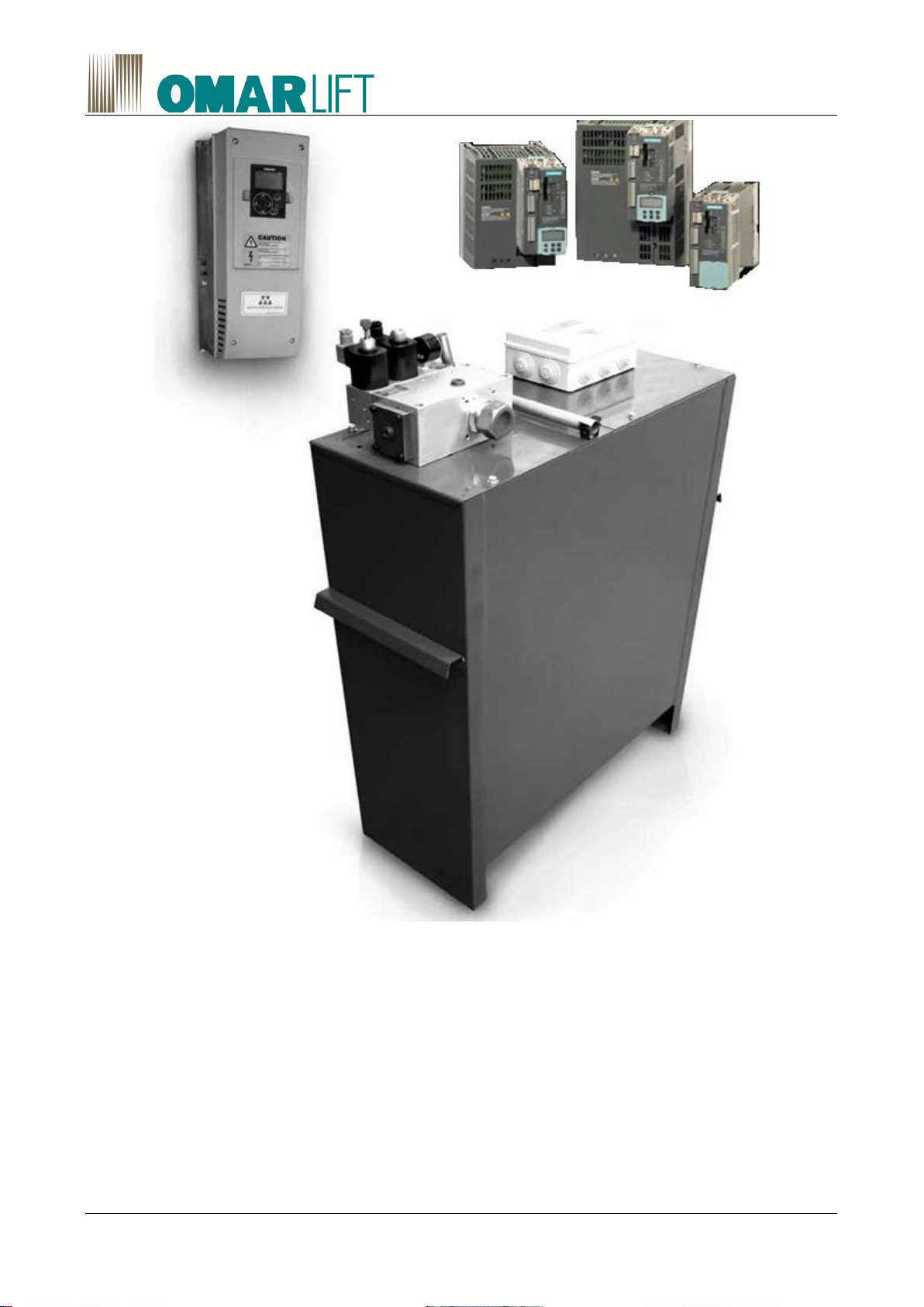
2.2 PUMP UNITS..................................................................................................................................... 6
2.3 INVERTER......................................................................................................................................... 7
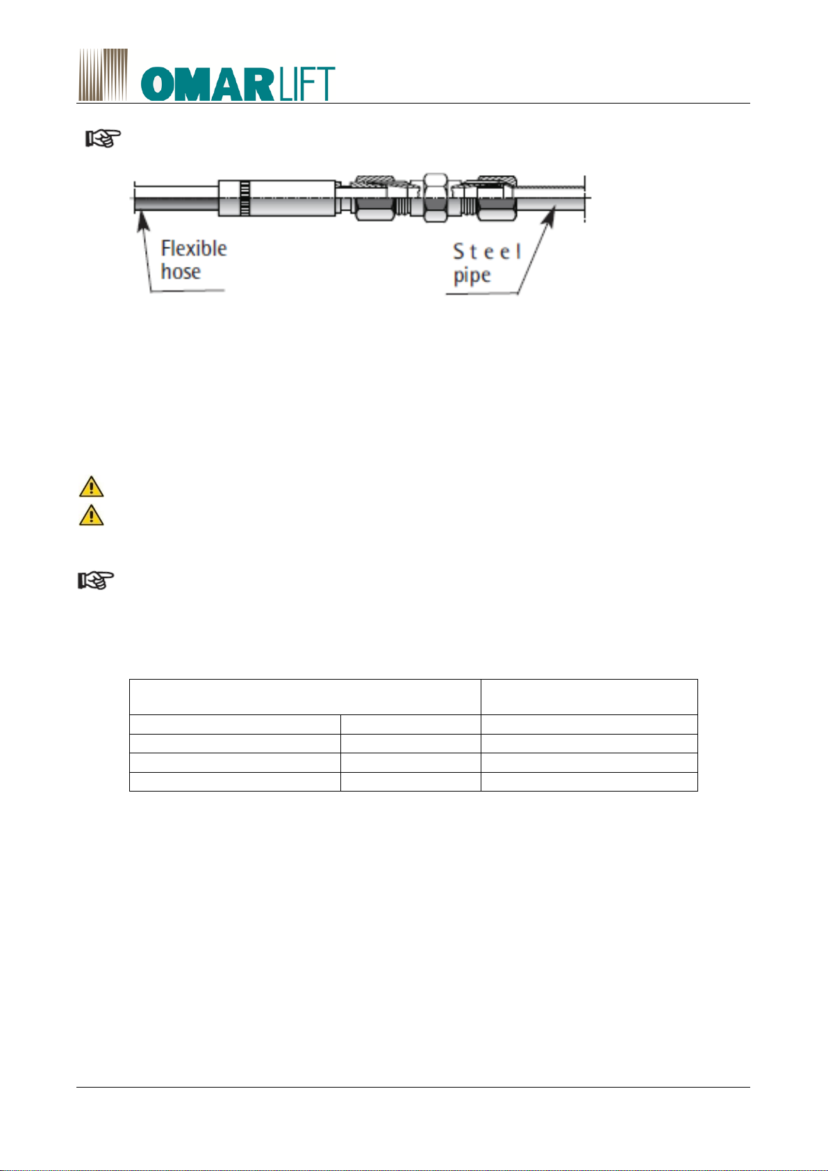
2.4 FLEXIBLE HOSES AND RIGID PIPES............................................................................................. 7
3ASSEMBLING OF THE HYDRAULIC COMPONENTS ............................................................................ 7
3.1 PUMP UNIT....................................................................................................................................... 7
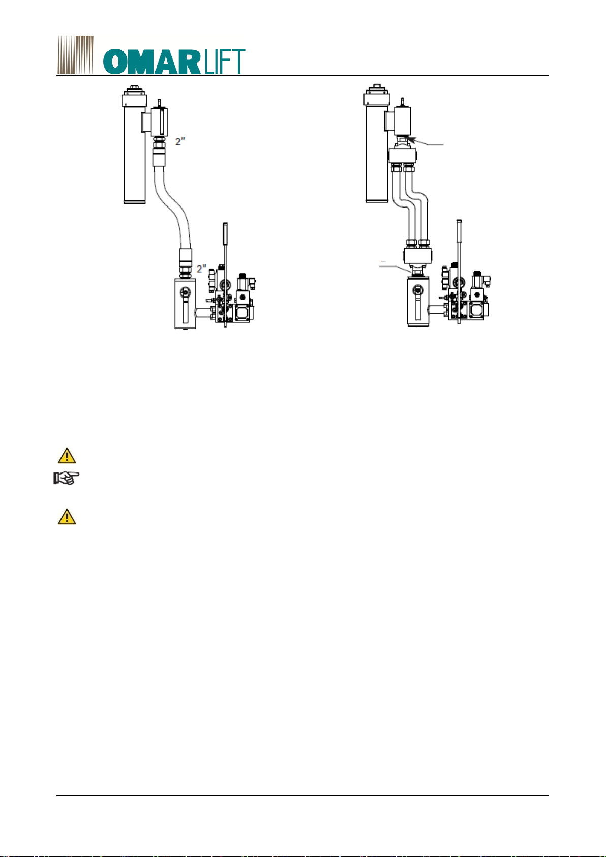
3.2 PIPE AND HYDRAULIC CONNECTIONS ........................................................................................ 7
4ELECTRICAL CONNECTIONS................................................................................................................. 9
4.1 GENERAL REGULATIONS............................................................................................................... 9
4.2 CONNECTION BOX.......................................................................................................................... 9
4.3 ELECTRICAL CONNECTION OF THE THREE-PHASE MOTOR.................................................. 10
4.4 MOTOR PROTECTION WITH THERMISTORS............................................................................. 11
4.5 ELECTRICAL CONNECTION OF THE VALVE GROUP................................................................ 11
4.6 POSITIONING OF THE SHAFT SWITCHES FOR THE DECELERATION DISTANCE................. 12
4.7 ELECTRICAL GROUP INVERTER................................................................................................. 12
INTRODUCTION ..................................................................................................................... 12
WARNING................................................................................................................................ 12
5OIL FOR LIFTS - CIRCUIT FILLING AND AIR PURGING ..................................................................... 13
5.1 CHARACTERISTICS....................................................................................................................... 13
5.2 CHOICE OF THE OIL...................................................................................................................... 13
5.3 CIRCUIT FILLING AND AIR PURGING.......................................................................................... 14
6CONTROLS AND TEST.......................................................................................................................... 16
6.1 CHECK OF THE OIL LEVEL IN THE TANK ................................................................................... 16
6.2 CHECK OF THE MAX. PRESSURE ............................................................................................... 16
6.3 CHECK OF THE START IN UPWARD DIRECTION....................................................................... 16
6.4 CHECK OF THE SEALING OF SEALS AND PIPES ...................................................................... 16
6.5 CHECK OF THE RUPTURE VALVE INTERVENTION................................................................... 17
6.6 CHECK OF THE INSTALLATION AT TWICE THE STATIC PRESSURE...................................... 17
6.7 CHECK OF THE ROD COUNTER-PRESSURE AND HAND WORKING ...................................... 17
6.8 CHECK AND ADJUSTING OF THE HAND PUMP......................................................................... 17
6.9 NOISE.............................................................................................................................................. 17
6.10 MANOMETER SHUT-OFF.............................................................................................................. 18
7ADJUSTING AND TEST OF THE OMARLIFT RUPTURE VALVE......................................................... 18
7.1 GENERAL INFORMATION ............................................................................................................. 18

D860MGB rev04
7.2 TEST AND WORKING OF THE RUPTURE VALVE....................................................................... 18
8VALVE GROUP AND INVERTER’S PARAMETER CALIBRATION AND ADJUSTMENT ..................... 18
8.1 GENERAL INFORMATION ............................................................................................................. 18
8.2 HYDRAULIC SCHEME.................................................................................................................... 19
8.3 ADJUSTING AND REGULATION OF “HI” VALVE GROUP ........................................................... 20
OVER-PRESSURE VALVE CALIBRATION: SCREW N°1..................................................... 20
ROD COUNTER-PRESSURE AND ROPE ANTI-LOOSENING CALIBRATION: SCREW N. 3
20
CALIBRATION OF THE HAND PUMP PRESSURE: SCREW N. 9........................................ 21
CALIBRATION OF THE PRESSURE SWITCHES (PRESSURE MIN. - MAX. - OVERLOAD)
22
8.4 INVERTER SETTING AND PROGRAMMING................................................................................ 23
9OPTIONAL ACCESSORIES ................................................................................................................... 23
9.1 OIL HEATING RESISTANCE (optional).......................................................................................... 23
9.2 OIL COOLING (optional) ................................................................................................................. 23
GENERAL INFORMATION ..................................................................................................... 23
COOLING SYSTEM WITH AIR............................................................................................... 24
COOLING SYSTEM WITH WATER........................................................................................ 24
10 MAINTENANCE................................................................................................................................... 25
10.1 GENERAL INFORMATION ............................................................................................................. 25
10.2 OIL LOSSES AND CAR LOWERING.............................................................................................. 25
LOSSES ALONG THE PIPES................................................................................................. 25
CYLINDER LOSSES ............................................................................................................... 25
LOSSES INSIDE THE VALVE GROUP .................................................................................. 25
10.3 AIR PRESENCE IN THE OIL .......................................................................................................... 29
10.4 FILTER CLEANING INSIDE VALVE GROUP................................................................................. 29
10.5 MINERAL OIL DETERIORATION ................................................................................................... 29
10.6 ELECTRICAL ANTI-CREEP SYSTEM (RE-LEVELING) ................................................................ 30
10.7 EMERGENCY LOWERING WITH THE BATTERY......................................................................... 30
10.8 PLATES, DIAGRAMS, INSTRUCTIONS......................................................................................... 30
10.9 INVERTER MAINTENACE.............................................................................................................. 30
MEGGER TEST....................................................................................................................... 30
10.10 RECOMMENDED PERIODIC MAINTENANCE.............................................................................. 30
11 DIMENSIONS AND WEIGHTS............................................................................................................ 31
11.1 DIMENSIONS AND WEIGHTS OF THE PUMP UNITS.................................................................. 31
11.2 DIMENSIONS AND WEIGHTS OF INVERTER AND RESISTORS................................................ 31

D860MGB rev04 4/32
1 GENERAL INFORMATION BEFORE INSTALLING
1.1 INTRODUCTION
The assembly, installation, put into action and maintenance of the hydraulic lift have to be carried out only by
trained staff. Before starting with any kind of work on the hydraulic components, it is necessary that the
trained staff reads these operating instructions carefully; in particular chapters 1.3 “SAFETY MEASURES”
and 1.4 “WARNING ON HOW TO OPERATE”. These "Operating instructions" are an integral part of the
installation and have to be kept in a safe and accessible place.
1.2 LIABILITY AND GUARANTEE
These operating instructions are addressed to staff competent in installing, adjusting and maintenance
operations on the hydraulic lifts.
OmarLift does not take responsibility for any kind of damage caused by use different from the one hereby
explained, lack of experience, carelessness by people assigned to the assembling, repair operations of the
hydraulic components.
OmarLift guarantee is not valid anymore if components or spare parts different from the original ones are
installed, and if modifications or repair operations are carried out by non-authorized or non-qualified workers.
1.3 SAFETY MEASURES
Installers and maintenance staff are fully responsible for their safety while working. All the safety
measures in force have to be observed carefully to prevent competent staff or any possible non-
competent persons or objects, from damages or accidents. These operating instructions report
some symbols, which correspond to important safety measures:
Danger: This symbol draws attention to high risk of injury of persons.
It must always be obeyed.
Warning: This symbol draws attention to information which, if it is not observed, can lead to injury to
persons or extensive damage to property.
It must always be observed.
Caution: This symbol draws attention to information containing important instructions for use.
Failure to observe the instructions can lead to damage or danger.
1.4 WARNING ON HOW TO OPERATE
Hereby follow the most important principles which always have to be observed while working on hydraulic
installations. These principles will not be repeated in the following chapters, because they are considered to
be known.
SAFETY ON THE WORKING PLACE
Lack of observing simple safety rules or lack of attention can lead to even severe incidents. In case
of works on the hydraulic installation, it is necessary to:
•Get the lift to be at the bottom directly on the buffer;
•Block the main switch to be sure that the lift cannot be put into service unintentionally;
•Get the oil pressure to zero before opening any part of the hydraulic circuit, caps or unscrewing
fittings.
•Prevent cinders from getting in contact with oil, rod and its seal and all the elastic parts of the
installation during welding operations;
•Get rid of the spilled oil, oil leakage, keep the installation always clean so that any leakage can be
easily detected.

D860MGB rev04 5/32
CLEANING
Cinders and dirt inside the hydraulic installation cause bad working and precocious wear.
Before assembling, it is necessary to clean the different parts with a lot of care:
- All the possible protection caps, plastic bags and tape used for packing have to be removed.
- The connection pipes, whether they are flexible or iron have to be cleaned perfectly from the inside.
Especially the iron pipes have to be cleaned from the inside and cinders have to be removed from
the ends. A pipe bender, not flame, has to be used to bend the iron pipe.
- Before pouring the oil into the pump unit tank, check that no dirt or water is inside it.
- Use always a good filter to pour or add oil in the tank.
- For the cleaning of the pipes and the pump unit do not use fraying clothes or steel wool.
- The cylinder head and all the plastic or rubber parts have to be protected if paint, concrete or
welding machines are used in their neighborhood.
- All the parts of the installation which have been disassembled to be tested or repaired, the sealing
surfaces, the pipes and the fittings have to be cleaned perfectly before being reassembled.
INSTALLATION
For the installation or the replacement of the hydraulic installation components, the following points have to
be observed:
- Only use the material advised by OmarLift (especially the hydraulic oil) and the original OmarLift
spare parts.
- Avoid the use of sealing materials such as silicone, plaster or hemp which could penetrate the
hydraulic circuit.
- In case of pipes bought directly from the market are being used, only choose the ones responding to
the safety measures in force and according to the pressure of the installation. Note that the only use
of the hard pipe to connect the pump unit to the cylinder can transmit and increase the noise.
- Install the flexible hoses with the right bending radius suggested by the manufacturers and avoid the
use of hoses which are longer than necessary.
MAINTENANCE
During the periodical works of maintenance besides normal tests, it should be remembered that:
- The damaged pipes have to be replaced immediately.
- Get rid of oil leakage and its causes.
- The possible spilled oil has to be collected, so that leakage can be easily detected.
- It’s necessary be sure that there are no unusual and excessive noises in the pump, the motor or the
suspensions. Eventually, get rid of them.
ANTI-POLLUTION MEASURES
Possible spilled oil from the circuit during repair operations has not to be spread in the environment, but has
to be promptly collected with cloths or sponges and disposed carefully in proper containers. In case of oil
replacement, also the waste oil has to be disposed in proper containers.
For the disposal of oil and clothes containing oil contact the specialized companies according to the
regulations in force in the country of operation. Concerning the rules against the water pollution (see
underground direct acting installations with high quantities of oil) act according to the national rules.
1.5 CONTROL OF THE SUPPLIED MATERIAL
When the material is withdrawn before signing the delivery document of the forwarding agent, check that the
goods correspond to the list reported in the delivery document and to the requested order.
1.6 IDENTIFICATION PLATES
The main supplied components have their own plate containing all the data needed to identify them:
- Cylinder: adhesive plate on the cylinder head.

D860MGB rev04 6/32
- Rupture valve: plate fixed on the valve side.
- Pump unit: plate fixed on the tank cover.
- Flexible hose: test date, test pressure and manufacturer name engraved on the fitting.
1.7 FEATURES OF THE MACHINE ROOM
Before installing:
- Make sure that the shaft, pit, head and machine room correspond to the project data and respond to
the regulations in force, and:
- Make sure that access ways allow the passage of the different components to be installed.
- Make sure that the bottom of the pit is clean, dry and waterproof.
- Make sure that the shaft is ventilated and illuminated sufficiently.
- Make sure that the machine room has the access door with opening towards the outside, if possible
noise-proof, well-ventilated and its temperature preferably between 10 and 30 °C.
2 TRANSPORT AND STORAGE
2.1 GENERAL INFORMATION
For the transport and the storage of the hydraulic components, the general safety regulations always have to
be followed:
When loads have to be lifted, only use proper hoists and respect their max. capacity.
Never walk or stop under the hanging loads.
Avoid hydraulic components from shocks.
- If the hydraulic components have to be stored, first control that packaging and protections are in a
perfect state; if necessary repair or replace them with other more suitable ones.
- Store the hydraulic components in a dry place, dust free with a temperature between 5 and 30°C.
- If the cylinders or the pump units have to be stored for a long time, it is better for the preservation to
fill them with oil to prevent oxidation phenomena.
2.2 PUMP UNITS
The pump unit is protected by a thermo-shrinking plastic cover and plastic film. In case customers ask, the
pump unit can be packed in resistant cardboard or in a wooden cage.
TRANSPORT OF PUMP UNITS
•Load and unload the pump units using clamp trucks. If the pump unit has to be lifted with ropes,
make them pass under the handles (see Figure 1).
•The pump units cannot be placed on each other, if not packed in special wooden cages designed to.
Figure 1- Pump unit lifting with ropes

D860MGB rev04 7/32
STORAGE OF THE PUMP UNITS
•Store the pump units in a dry place with a temperature between 5 and 30°C.
•Control the protection packaging and replace it if necessary..
•If the pump units have to be stored for a long time, it is better to fill the tank with oil, at least until to
cover the electric motor.
2.3 INVERTER
The inverter is delivered in a special packing or in a cardboard box.
STORAGE OF THE INVERTER
•Store the inverter in a dry place at a temperature between 5° and 30°C.
•Check the protective packaging and eventually replace it.
2.4 FLEXIBLE HOSES AND RIGID PIPES
PIPES TRANSPORT
•Avoid harsh bending of the flexible hoses.
•Prevent the flexible hoses from contact with caustic essences, solvents or other chemical
substances.
•Transport the flexible hoses in their original packaging.
•Avoid any kind of bending of the rigid pipes.
•Transport the rigid pipes with their caps on the ends.
STORAGE OF THE PIPES
•Store the pipes in a dry place, with a temperature between 5 and 30°C.
•Prevent the flexible hoses from the direct sunlight or the near presence of a heat source.
•Do not keep the flexible hoses stored for more than 2 years from the test date engraved on the fitting.
3 ASSEMBLING OF THE HYDRAULIC COMPONENTS
3.1 PUMP UNIT
The serial number of the pump unit is reported on the plate on the tank cover.
- All the pump units and the shut-off valves are tested and adjusted before the delivery.
For this reason they can work immediately, without any further adjusting.
When the installation has been finished, the oil filled and the air purged, it will be possible to readjust the low
speed and the deceleration to optimize the installation working (see instructions in paragraph 8.4)
The pump unit room has to be located as close as possible to the lift shaft, has to be big enough,
with an almost constant temperature, possibly heated in winter and ventilated in summer. If
distances are bigger than 8-10 meters, please consider the pressure loss along the main pipe.
Avoid noise transmission by using anti-vibration pads under the tank and a flexible hose for the
connection of the pump unit to the cylinder.
- The tank is equipped with handholds to be displaced manually and to be lifted with an hoist (see
Figure 1).
3.2 PIPE AND HYDRAULIC CONNECTIONS
Use cold drawn steel tubes, normalized and bonderized, special for hydraulic circuits, flexible hoses which
are tested and certified for high pressure or mixed connections to connect the pump unit to the cylinder.
- The shut-off valve can be turned to be better aligned with the pipe direction.
The shut-off valve can be turned to be better aligned with the pipe direction.
The main oil pipe as to be as short as possible and avoid narrow bending. The use of elbow fitting

D860MGB rev04 8/32
has to be as reduced as possible.
When a rigid pipe is used, please note that:
•The pipe cut has to be perfectly at 90°.
Figure 2 - "WALFORM" fitting
•Possible bends have to be made when cold, using a proper pipe bending.
•The use of a flame can cause cinders inside the pipe.
•Cinders and dirt caused by the cut have to be completely eliminated
•When connecting two pipes to a cutting ring, make sure that the two pipes are perfectly aligned and
that the cutting part of the ring is turned towards the end of the pipe. Before tightening the nut of the
fitting, oil both the thread and the ring. Therefore screw with power and unscrew to control that the
cutting ring has engraved. Finally, screw again definitely the nut of the fitting, tightening it well.
Non-normalized pipes are too hard and they can get out of the fitting!
Warning: some countries do not allow the use of a joint with a cutting ring. In these cases, it is
necessary to use a type of fitting called "WALFORM" for the connection (see Figure 2) or fittings to
be welded.
When a flexible hose is used, please note that:
•The flexible hose has not to be subject to tension, torsion and the bends have to be as wide as
possible
•The minimum bending radius given by the manufactures has to be respected. It is reported in the
following table:
TYPE OF FLEXIBLE PIPE
MINIMUN RADIUS
3/4”
DN 20
240 mm
1 1/4”
DN 32
420 mm
1 1/2”
DN 40
500 mm
2”
DN 50
660 mm
The pump units with a capacity from 360 to 600 l/min have a 2" outlet. These pump units can feed a single
cylinder with a rupture valve 2" or two cylinders together.
- In case of a single cylinder, the connection between the pump unit and the rupture valve can be made:
•With a single flexible hose 2" and nipples 2", 60° angle (see Figure 3);
•with two parallel steel pipes, diameter 42 mm and two three-way fittings 1 ½”x 2” x 1 ½” (see Figure
4)

D860MGB rev04 9/32
•
Figure 3 - Connection with flex hose 2”
Figure 4 - Connection with two rigid pipes Ø 42
4 ELECTRICAL CONNECTIONS
4.1 GENERAL REGULATIONS
Any electrical connection has to be carried out by trained and qualified staff, according to the specific
regulations.
Before starting any kind of work, always disconnect the electrical power opening the general switch.
The cables for the electrical power feeding have to have a section sufficient for the requested power.
Their isolation has to be suitable according to the voltage of the electrical network. The connection
cables have not to be put in contact with parts subject to strong heating.
The grounding cable has to be always connected to the bolt marked with the proper symbol.
4.2 CONNECTION BOX
The connection box is on the pump unit cover, near the valve block..
•The box of the standard pump unit includes (see Figure 5):
a) Terminal block of the electrical motor
b) Grounding bolt
c) Thermostat for oil temperature 70°C
d) Motor thermistors 110°C
•The pump unit box, cabled (optional), includes (see Figure 6):
a) Therminal block of the electrical motor
b) Grounding bolt
c) Terminals of the thermostat for the oil cooling (optional.)
d) Terminals of the max pressure switch (optional.)
e) Terminals of the min pressure switch (optional.)
f) Terminals coil EVD
g) Terminals coil EVE
h) Terminals of motor thermistors 110°C
i) Terminals of the oil thermostat 70°C
j) Terminals of the overload pressure switch (optional.)
2”
2”
2 x (1½” - Ø42)
2 x (1”½ - Ø42)

D860MGB rev04 10/32
Figure 5 - Connection box for standard pump unit
4.3 ELECTRICAL CONNECTION OF THE THREE-PHASE MOTOR
The terminals of the motor are already fixed to the terminal block inside the connection box.
•In case of a direct start of the motor, frequency and one tension of the motor have to correspond to
the frequency and tension of the electrical power network.
The connection bands on the terminal block have to respect the diagram appearing on the motor
plate or the directions of the table (see Figure 7).
Figure 6 - Connection box for wired pump unit
DISPOSITION OF TERMINAL CONNECTION BANDS FOR THREE-PHASE MOTORS
DIRECT START

D860MGB rev04 11/32
Line 230V -Motor 230/400
Line 400V -Motor 400/690
Line 415V -Motor 415/720
Line 400V -Motor 230/400
Line 690V -Motor 400/690
Line 720V -Motor 415/720
Figure 7 - Electrical connection of three-phase motors
4.4 MOTOR PROTECTION WITH THERMISTORS
The motors, which work covered with oil, are supplied with their thermistors 110°C. The thermistors are
inserted in windings, one for each phase and they are connected in series.
Their resistance remains very low, under 110°C, but increases drastically when 110°C are reached in one or
in all windings.
For the motor protection, the thermistors have to be connected to a proper release electronic relay
susceptible to the resistance variation.
Warning: The thermistors have not to be submitted to tensions higher than 2,5 V.
When the thermistors are properly connected, they protect the motor against the overheating of the windings.
Overheating could be caused by:
- lack of a phase in the feeding
- too frequent activation
- excessive tension variations
- excessive oil temperature
4.5 ELECTRICAL CONNECTION OF THE VALVE GROUP
The HI valve (see Figure 8) entails the following electro-valves:
•The EVD ELECTRO-VALVE controls normal downward travel.
This electro-valve should be powered only during downward travel throughout the entire run.
•EVE ELECTRO-VALVEV this electro-valve is used for emergency downward travel.
By powering the coil, the hydraulic valve will allow the slow speed downward travel of the car.
Figure 8 –Position of coils on the HI valve

D860MGB rev04 12/32
4.6 POSITIONING OF THE SHAFT SWITCHES FOR THE DECELERATION
DISTANCE
Legenda:
F - Stop switch before landing (20-30 mm) (the soft stop travel is controlled by the inverter)
S –Upward travel deceleration distance (shaft switch)
D –Downward travel deceleration distance (shaft switch)
To achieve a good deceleration the contact at the entrance 9 of the inverter high speed, must be opened at a
distance from the arrival floor, that depends on the speed: the greater the distance, the higher the speed of
the unit.
The opening distance of the entrance high speed from landing be inferred by the following table:
Car
Speed
EVD de-energizing
Upward distance
Downward distance
0,40 m/s
0,50 m
0,60 m
0,60 m/s
0,70 m
0,80 m
0,80 m/s
0,90 m
1 m
4.7 ELECTRICAL GROUP INVERTER
INTRODUCTION
OmarLift uses an inverter which operates in open loop condition, with a special software for hydraulic lifts. It
controls both the upward run and the downward run.
You can achieve the following benefits:
•No starting current peaks. The maximum starting current never exceeds the nominal current.
•Power Factor correction. Cosφ ≥ 0,97.
•Energy saving.
•Run comfort optimization.
•Adjustable inspection speed
•You can set a maximum limit (optional) for the absorbed power from the mains, in order to reduce
the installed power.
WARNING
Read the manual of the inverter in its entirety before powering up the equipment, following the
procedures step by step.

D860MGB rev04 13/32
Follow the procedures in the manual of the inverter to not risk serious injury, to avoid the risk of
damage the inverter and the correctly connect the power circuit.
Do not power up the inverter without first making the connection to earth
5 OIL FOR LIFTS - CIRCUIT FILLING AND AIR PURGING
5.1 CHARACTERISTICS
The hydraulic oil is a very important part of the hydraulic installation.
In particular, in case of installations having medium or high traffic, "THE CHOICE OF GOOD QUALITY OIL
INCREASES THE TEMPERATURE RANGE WITHIN WHICH THE LIFT WORKS IN A COMFORTABLE
WAY AND INCREASES THE DURATION OF ITS HYDRAULIC COMPONENTS".
A good quality oil for lifts has to have the following main characteristics:
1) Viscosity at 40°C:
= 46 cSt, oil suitable for low temperatures, in particular for the first starts in the morning.
= 68 cSt, oil suitable for high temperatures, in particular caused by high traffic.
2) Viscosity index:
≥150, oil suitable for low and medium traffic.
≥180, oil suitable for medium/high and high traffic.
3) Flash point: > 190°C
4) Pour point: < -35°C
5) Specific weight a 50°C: = 0,88 kg/dm³
6) Air release a 50°C: < 6
For a quick separation of the air and the elimination of the oil foam.
7) Further characteristics:
- Anti-oxidant: It prevents the creating of dirt and dregs.
- Anti-corrosion: It doesn’t corrode metals, copper, seals etc.
- Anti-wear: It assures the duration of the moving parts.
- Anti-rust: It protects and conserves the metallic components.
- Anti-emulsion: It makes the spontaneous separation of water from oil easy.
5.2 CHOICE OF THE OIL
The oil has to be chosen focusing on the installation characteristics (temperature and ventilation of
the machine room, installation traffic) as well as on the temperature-viscosity characteristics of the oil..
In particular it should be noted that the names of the hydraulic fluid:
- The number which follows the type or the name of the oil shows only the oil viscosity when its
temperature is 40°C. (es. 32/46/68 cSt ecc.).
- The viscosity index shows the oil stability when the temperature changes. The oil viscosity increases
when the oil cools and decreases when the oil heats. These variations are important if the viscosity
index is low, consequently "IT IS RECOMMANDED TO USE OILS WITH A HIGH VISCOSITY
INDEX, 150/180/190 according to the situations".
Oils with a low viscosity index, such as 98/110/120, have to be used in installations with an almost
constant room temperature and a number of travel per hour not higher than 8/10. The installation works
well if the viscosity variation is between 250 and 40 cSt about. This can be obtained with an oil having a
high viscosity index, when the temperatures go from 8/15°C to 50/60°C. Oil can be heated or cooled with
proper resistances or heat exchangers to keep the temperature back within the right levels or optimize
the installation working.
Oil has to be heated (optional) when the machine room temperature reaches low values which could
jeopardize the installation working during the first travels in the morning. The car has to be drawn

D860MGB rev04 14/32
back to the lowest floor automatically, not later than 15 minutes after the last travel. In this way all the
oil in the tank can be heated. An electrical resistance (500 W) with thermostat is normally used to
heat the oil in the tank.
Oil has to be cooled when the high number of travels makes the temperature increase, exceeding
the acceptable temperature for the used oil, or reaching the max. temperature of 70°C, making the
safety thermostat intervening.
Oil heats not only because of the high traffic, but also because the machine room is small, not
ventilated, is placed under the roof or the oil in the tank reaches the minimum indispensable quantity.
For the oil cooling, systems with air or with water can be used.
The types of oil fit to be used with the HI unit are the following:
Oil type
Viscosity Index
WHD OIL 46 Base
101
WHD OIL 46 Plus
140
WHD OIL 46 High
160
•The list which follows shows examples of some types of oil which, thanks to their characteristics, are
suitable for the lift field.
The oils shown are not the only ones which can be used. No preference or qualification has been given to
the order of the list:
PRODUCT
BRAND
WORKING CONDITIONS
LOW-MEDIUM
WORKING CONDITIONS MEDIUM HIGH -
HIGH
Type
Viscosity index
Type
Viscosity index
AGIP
H LIFT –46/68
150
ARNICA 46/68
164
API
APILUBE HS 68
150
CASTROL
HYSPIN M46
160
HYSPIN M68
190
ESSO
INVAROL EP 46
160
INVAROL EP 68
180
FINA
HYDRAN HV 68
151
I.P.
HYDRUS HI 46
HYDRUS HX 68
175
OLEOTECNICA
MOVO M 46/68
154
MOVO HVI 46/68
182
ROLOIL
LI/46 –HIV
160
LI/688 –HIV
175
SHELL
TELLUS T 46
153
TELLUS T 68
193
SHELL
ELEVOIL 68
183
TOTAL
EQUIVIS HZS 46/68
160
EQUIVIS HZS 68
Tab. 1 –Some oil alternatives
No responsibility is taken for differences or variations of types and characteristics made by the oil
manufactures.
5.3 CIRCUIT FILLING AND AIR PURGING
When an installation is new, the tank, the cylinder, the connection pipes, the valve and the silencer have no
oil inside. Consequently, it is necessary to fill very well all the components of the hydraulic circuit and purge
air out of them completely.
The quantity of oil to be put in the installation has to be the max allowed, in order to have a very
silent installation, without foam in the oil, and very low overheating.
The max quantity of oil necessary for the installation corresponds to the sum of the oil needed to fill
the tank, plus the oil needed to fill the cylinder (space between the cylinder and the rod), plus the oil
needed to fill the pipes. The following tables show the needed quantity of oil to fill the three parts
correctly:
The oil filling has to be done pouring the oil from the side of the moving half-cover, bringing the level
at 8/10 cm about from the upper edge.
Before pouring the oil into the tank, make sure that there is no dirt or water inside, if necessary,
remove them.

D860MGB rev04 15/32
The air has to be purged from the highest point of the circuit which normally is the cylinder head. The
oil has to enter the circuit very slowly, without creating turbulence and mixing with air.
Must also be left the time required to air to bleed out from appropriate bleeding
Operate as follows to get rid of the air completely (see Figure 9).
TOTAL AMOUNT OF OIL IN THE CIRCUIT = A+B x TRAVEL (m) + C x LENGHTH (m)
1- OIL FOR TANK = “A” CAPACITY
TANK TYPE
110
210
320
450
680
CAPACITY “A” - LITRES
100
200
305
430
650
2- OIL FOR CYLINDER (FOR THE FILLING UP WITHOUT TRAVEL) = “B”
ROD DIAMETER
mm
50
60
70
80
90
100
110
120
130
150
180
200
230
OIL “B” l/m
3.1
4,5
5
3,8
5,7
5,6
6,4
6,1
8,5
8,3
15,6
18,9
19,4
3- OIL FOR CONNECTION PIPES = “C”
PIPE
Ø22 x 1.5 flex ¾”
Ø35 x 2.5 flex 1¼”
Ø42 x 3 flex 1½”
N° 2 tubi x Ø42 x 3
Flex 2”
OIL “C” l/m
0,30
0,70
1,00
2,00
1,90
1) Unscrew completely and remove the purge screw on the head of the cylinder (or cylinders).
2) If the rupture valve is not adjusted (red label on it), its regulation screw has to be unscrewed.
3) With pushbutton maintenance, make a call breathes (low speed).
4) Carry out an upward start and check the direction of rotation of the motor. If the direction of
rotation is wrong, a pump cavitation noise will be heard. It shall then be necessary to exchange
two phases on the motor connection.
5) Keep the motor activated for 10 –15 seconds and stop it for 20 - 30 seconds to allow the air to
go out.
Repeat this operation several times, until only oil, without air, comes out from the purge screw.
6) Close the purge screw of the cylinder and adjust the rupture valve, in case it has not been
adjusted previously in the factory.
If the rupture valve needs to be adjusted, carefully follow the operating instructions enclosed to it,
or the directions in chapter 7 "ADJUSTING AND TEST OF THE OMARLIFT RUPTURE VALVE".
7) Reset the oil level in the tank, if necessary and make an upward travel at low speed, checking
that all the parts of the installation are in order and that the oil quantity is sufficient. The motor
has always to be covered by oil even when the cylinder is at the upper end.
Avoid that the oil level decreases until it uncovers the motor-pump group.
In this case in fact the pump could suck air, making all the above purging operations void.
8) Check that in the circuit there is no remaining air. At this purpose, stop the car on an
intermediary floor, close the shut-off valve and turn off the power, get into the car and check that
there is no strong lowering, get off the car and verify that the car does not go quickly back to its
initial position.

D860MGB rev04 16/32
Figure 9 –Position of Screws for purge and for the rupture valve regulation
6 CONTROLS AND TEST
After the assembling operations have been completed, after the oil has been filled and the air has been
purged from the circuit, it is proper to make the following checks:
6.1 CHECK OF THE OIL LEVEL IN THE TANK
•When the cylinder is in upper end position, check that the oil level in the tank covers the motor-pump
group well (min. 2 cm over the motor).
•When the cylinder is in lower extra-travel position, the oil level has to be 7/8 cm under the tank edge.
6.2 CHECK OF THE MAX. PRESSURE
•When the main line shut-off valve is closed, the motor activated for the upper travel, the oil
discharges into the tank and the manometer shows the max. adjusting pressure of the overpressure
valve.
•The value of the max. adjusting pressure has to correspond to 1,4 times the max static pressure with
full load.
6.3 CHECK OF THE START IN UPWARD DIRECTION
In order to get a smooth start of the motor in upward direction without load, be sure that:
•When the shut-off valve is closed, discharge pressure using the emergency button and start up the
motor again: check that the pressure rises slowly from its minimum to its maximum value.
If necessary, adjusting the parameters of the inverter.
6.4 CHECK OF THE SEALING OF SEALS AND PIPES
Check visually the connection pipe sealing, in particular the joints of the flexible hoses and rigid pipes.
After some travels, the rod looks covered by a small quantity of oil needed for its lubrication.
A possible oil ring on the rod could appear in the first working days because of deformation or hardening of
the seal, in particular if the cylinder has remained laid down for a long time on the site.
This phenomenon will disappear after a short period of time. Only if there is a huge oil quantity in the
recovery tank, it will be necessary to replace the seals.

D860MGB rev04 17/32
6.5 CHECK OF THE RUPTURE VALVE INTERVENTION
Be sure that the rupture valve has already been adjusted. If necessary, regulate it according to the handbook
for the adjusting operations or the instruction reported.
The down travel intervention test has to be carried out when the car has been loaded with the nominal load
uniformly distributed according to the instructions reported in paragraph 7.2 "TEST AND WORKING OF THE
RUPTURE VALVE".
6.6 CHECK OF THE INSTALLATION AT TWICE THE STATIC PRESSURE
This check has to be carried out only after the check of the rupture valve intervention and when the oil
temperature is constant.
The oil has not to be hot: the test has to be carried out only when the oil temperature is the same as the
room temperature (please note that in a close circuit, the temperature variation of 1°C can cause a pressure
variation of 9 bar):
- If necessary, determine the max. static pressure loading the car with the nominal load.
- Take the piston to upper end position with the main motor until the adjusting pressure is reached and
stop in this position.
- Increase the pressure slowly with the hand pump until double the max. static pressure.
- Check pressure fall and losses within 5 minutes, taking into account the possible effects due to the
oil temperature variation. If necessary, repeat the test, re-charging the pressure for 2/3 times with the
hand pump, controlling that pressure does not decrease by 5/6 bar during the first 4/5 minutes. If
needed, read paragraph 10.10. “Periodical recommended maintenance sheet”.
- When the test has finished, take back the pressure to the value of the static pressure, activating the
emergency button manually and control visually the integrity of the hydraulic system.
6.7 CHECK OF THE ROD COUNTER-PRESSURE AND HAND WORKING
- For indirect acting installations 2:1, check that, when the car is blocked on the proper parachutes or
lays on its dampers, by activating the red emergency button, the rod does not go down making the
ropes loosen. If necessary, screw the screw n. 3 until it stops.
- For any kind of installation, check that, when the car is free to go down, it goes down regularly at a
reduced speed when the emergency button is pushed.
6.8 CHECK AND ADJUSTING OF THE HAND PUMP
When the main shut-off valve is closed, activating the hand pump, the pressure on the manometer has to
increase up to the adjusting value.
The safety valve of the hand pump has to be adjusted at 2,3 times the static pressure of the installation with
full load.
The regulation screw of the hand pump is on the left of the lever. If necessary, see instructions at point 8.3.3
for the regulation.
6.9 NOISE
The noise of OmarLift pump units is normally very low, especially during transistors (start / slowdown
example).
With average working conditions, when oil temperature is at 30/40°C and pressure at 25/30 bar, noise does
not normally exceed the following values:
•pump unit up to 210 l/min: 56÷58dBA
Anyway some external causes can determine an increase in the noise transmission of the installation: in fact
the noise is sometimes transmitted or even expanded by the building walls or by the connecting pipes, thus
reaching the lift space or the rooms next to it. When it happens it is necessary to operate as follows:
1) Use some thick rubber to isolate the connecting pipes from collars used to fix the pipes to the walls.

D860MGB rev04 18/32
2) Use some thick rubber to isolate both the cylinder head from its fixing collar and the cylinder bottom
from its support.
3) To connect the pump unit to the cylinder use a piece of flexible hose placed near the pump unit
which has to be at least 5/6 meters long.
4) Add some oil in the tank up to the maximum level allowed.
5) Make sure that the pipe discharging oil from the valve to the tank, always discharges under the tank
oil level.
6) Check that there is no air in the oil.
6.10 MANOMETER SHUT-OFF
The manometer, which is placed on the valve group, is supplied with an exclusion shut-off. During the
regular working of the lift, the manometer shut-off has to be perfectly closed to avoid possible oil losses or
damage to the manometer itself.
7 ADJUSTING AND TEST OF THE OMARLIFT RUPTURE VALVE
7.1 GENERAL INFORMATION
- The rupture valve is the hydraulic parachute assembled on the cylinder. It operates against the free
fall or the down travel with an excessive speed.
- The rupture valve has to be capable to stop the car during the down travel and keep it still, when the
downward speed exceeds the nominal speed +0,3 m/s at the latest.
- Practically it is possible to fix a speed increase corresponding to 30% of the nominal speed. This
value covers all the applications until the max admitted speed for hydraulic installations: 1 m/sec.
- The car speed changes with the variation of the oil which goes through the valve: adjusting a valve
means limiting the passage to a minimum value which lets an oil quantity, lower than the adjusting
value, run free and blocks the oil flow when the adjusting value is reached.
For the calibration procedure, the appropriate manufacturer's manual.
7.2 TEST AND WORKING OF THE RUPTURE VALVE
a) Get the travel shaft free and be sure that the whole lift equipment is perfectly working.
b) Load the car with the nominal load and take it to the upper floor.
c) Activate the test parachute valve (VP) of the inverter.
d) Make a travel from the upper floor to the lowest one.
e) The car speed increases up to exceeding the nominal speed..
f) The rupture valve intervenes when the downward speed increases by 30% about with respect to the
nominal speed. As a result, the car decelerates up to stop.
g) If, after some-meter run at a speed higher than the nominal one, the rupture valve has not
intervened, stop the car pushing button "STOP"..
h) The trial function VP is automatically disabled after each test. To repeat the trial restart from point C.
i) When the test has finished, block the regulation screw with the lock nut and seal with red paint or link
the two proper holes, one located on the screw and the other on the valve block, with iron wire and plumb.
8 VALVE GROUP AND INVERTER’S PARAMETER CALIBRATION AND
ADJUSTMENT
8.1 GENERAL INFORMATION
The valve group is adjusted and tested in the factory together with shut-off valve, motor pump group and
inverter. When the regulation has been completed, a diagram is prepared which reproduces the speed
behavior during upward and downward travels. This diagram (see Figure 10) is supplied together with its

D860MGB rev04 19/32
pump unit. The identification plate (see Figure 11) lays on the pump unit cover and shows the valve drawing,
all the regulation points, the description of the electro-valves and all identification data.
Before any regulation of the valve or the inverter, verify:
- all the electrical connections have been carried out correctly.
- the oil in the tank is the advised one and it temperature is between 20 and 30°C.
Figure 10 - Upward and downward speed diagram
Figure 11 - Identification plate
8.2 HYDRAULIC SCHEME
Figure 12 - OmarLift HI valve: hydraulic circuit (without A3 device)

D860MGB rev04 20/32
8.3 ADJUSTING AND REGULATION OF “HI” VALVE GROUP
SCREW
DESCRIPTION
REGULATIONS
N° 1
Adjusting of the max pressure valve
screw to increase max pressure
unscrew to decrease max pressure
N° 3
Rod counter-pressure and rope anti-
loosening device adjusting
screw not to make the rod drop in emergency
unscrew to make the rod drop in emergency
N° 9
Hand pump pressure adjusting
screw to increase the hand pump adjusting pressure
unscrew to decrease the hand pump adjusting pressure
OVER-PRESSURE VALVE CALIBRATION: SCREW N°1
The over-pressure valve has to be adjusted with a pressure 1,4 times the max. static pressure with a
full load. (Higher values, corresponding max to 1,7 times, are also admitted, only if this possibility
has been taken into account during the project phase).
The max pressure is reached only when the piston is in upper end position or when the main line valve is
closed.
- Close the shut-off valve of the main line and open the manometer valve.
- Screw the screw n. 1 and discharge the possible pressure with the red manual emergency button.
- Start the motor in up direction.
- Screw the screw n. 1 until the max wanted pressure value is reached and stop the motor.
- Discharge again pressure with the hand button, activate the motor checking that the manometer
shows the adjusted pressure, block the nut and stop the motor.
In case the given pressure needs to be decreased, discharge the pressure with the hand button,
unscrew the screw n. 1 and repeat the adjusting.
ROD COUNTER-PRESSURE AND ROPE ANTI-LOOSENING CALIBRATION: SCREW N. 3
For security reasons, in indirect acting installations, the activation of the emergency button has not to
cause the rope loosening when the car is locked. For this reason, it is necessary that, inside the
Table of contents
Other OmarLift Water Pump manuals
Popular Water Pump manuals by other brands

Whale
Whale UF2025 Installation & user's instructions

Wilo
Wilo Atmos GIGA-N Installation and operating instructions

Pompetravaini
Pompetravaini BORA FP 243 operating manual

Reefe
Reefe RCE160 Exploded View & Instruction Manual

CountyLine
CountyLine CLRP50 owner's manual

Zipper Mowers
Zipper Mowers ZI-DOP600 Operation manual