-
-
-
1)
2)
3)
4)
5)
6)
7)
Soggetto a modifica senza preavviso! Subject to change without notice!
8)
9)
10)
11)
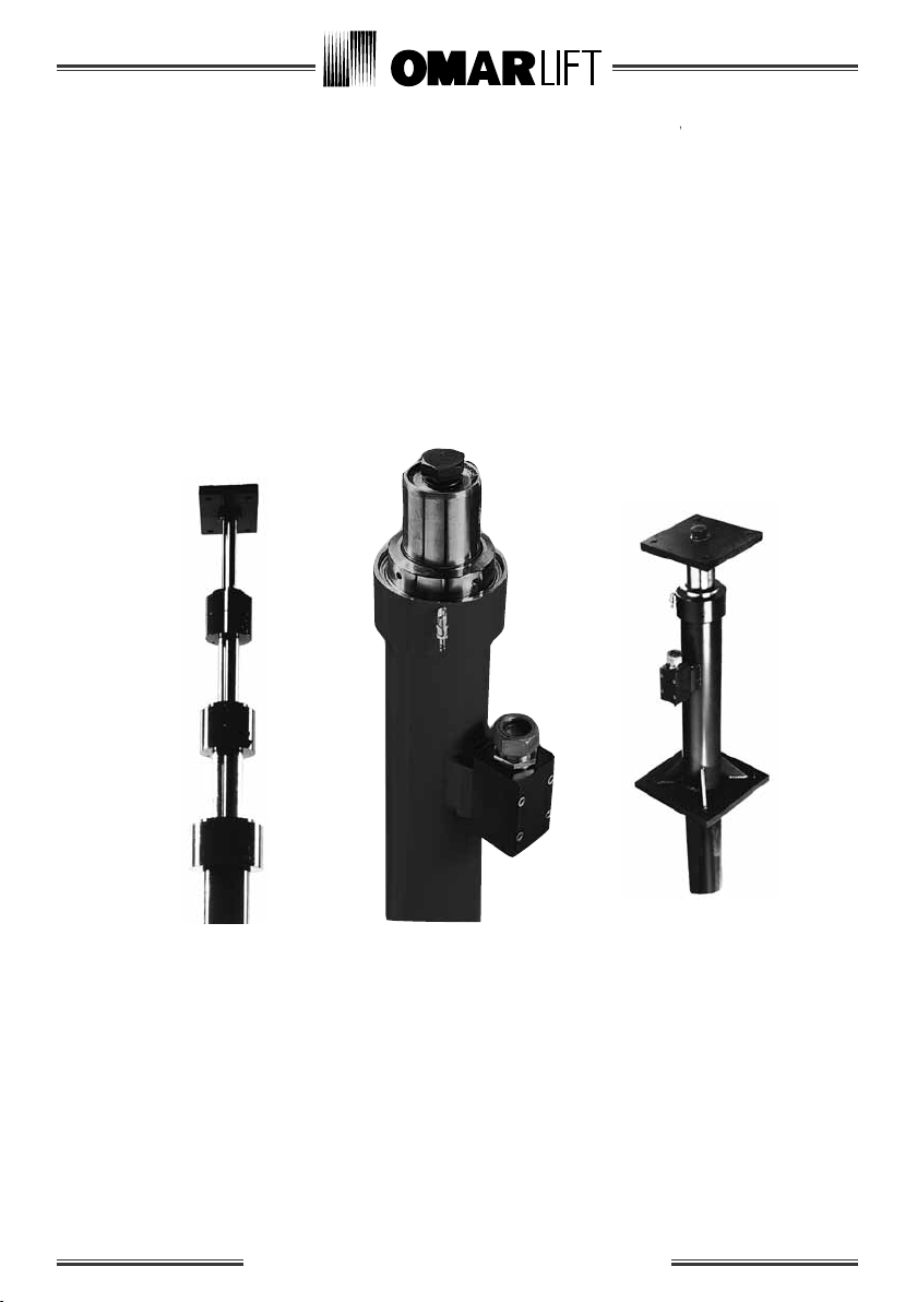
2.5 Cylinders in three pieces
1)
Pagina/Page D842MGB.006
Data/Date 09.2008
Versione/Issue 1
Hydraulic cylinders
Operating instructions
It is necessary, after having removed the protection
hoods, to put some rubber stripes between the rod
and the cylinder, in order to avoid damages to the
rod. These stripes have to be fixed well to the screws
of the flanges and have to be removed just before
closing the square flanges of the cylinder.
Follow the next operating instructions for the assembling
of the two pieces (see drawing n. 4):
Put the lower part of the cylinder in a perfect vertical
position and fix it, unscrew the screws that fix the
protection hood to the flange on the cylinder head.
Draw out the rod for a length of around 1/2 metre, fix the
special wrench or other tools well protected by rubber or
similar material. Then take the protection hoods away.
Remove the potection rubber on the upper half of the
rod.
Check if the upper block stirrup is present and if it
is fixed through the M30 screw.
Disassemble the rod protection hood unscrewing the
fixing screws.
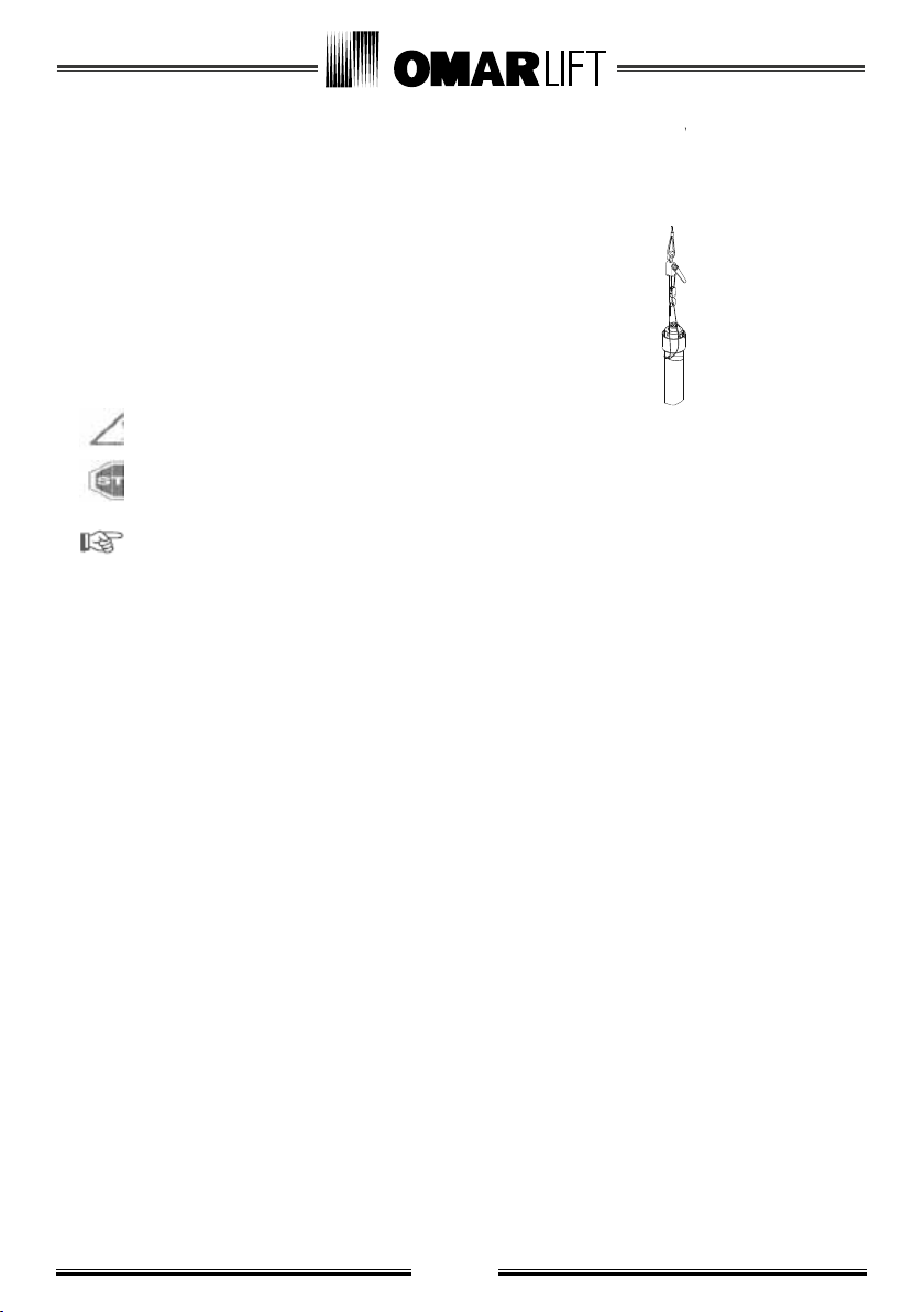
Lift the upper half of the cylinder with an hoist
fastening it to the holed plates welded on the head.
Let the rod draw out paying attention to avoid scriping
and knocks to the cylinder.
Block the rod of the upper half with a screwer or with
another tool insulated with rubber, without making it
come out of the head which contains the seals.
The block stirrup of the rod has to be removed only
when the operation has finished.
Remove grease and clean the male and female threads,
avoiding that the solvent contacts the OR of the joint.
Control carefully that there are no bruises neither
on the threads nor on the joint. If necessary, get rid
of them.
Control that the OR of the joint is not damaged and is
well greased.
Lower the upper half of the cylinder and slowly
approach the threads without harsh movements.
Control the alignment and completely screw
without using the thread-locking liquid.
If there are any difficulties with screwing, unscrew
immediately, control the threads and try again.
After having completely screwed the two halves, unscrew
by 4/5 turns, apply the thread-locking liquid on the screw
(not on the OR), quickly screw again, checking that the
red paint signs are aligned (max tolerance 4/5 mm).
Remove the screwers and control by hand that the
joint of the rod is perfect all around, without bruises
and steps. If necessary, smooth with fine abrasive
paper (grain 320-400).
Check that the OR of the lower flange is perfect and
positioned in its own housing. Clean the two flanges.
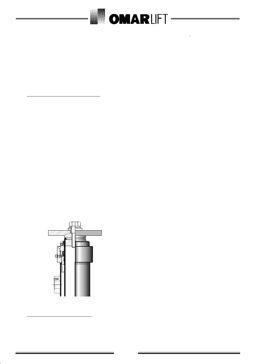
Pull the two square flanges closer, matching the pin
with the hole. Then screw the four screws that block
the flanges, tighting crosswise.
The upper half of the cylinder in two pieces has a rod
which is longer than the cylinder, so it is possible to fix
the screwer to the rod without disassembling the cylinder.
The two joints of the cylinder in two pieces are
hermetically closed by two metal hoods which act as a
protection and packaging during the transport.
In case of three pieces cylinders, we advice to proceed as
follows:
In the first step, assembly the cylinder lower part with
the intermediate one, considering these two parts as
being one cylinder in two pieces. To facilitate this
operation, the intermediate part jacket can be completely
unthreaded and put back after having assembled the first
two parts.
OMAR LIFT
Pagina/Page D842M2L.006
Data/Date 09.2008
Versione/Issue 1