OMEGA AIR AirWatt User manual

Installation and operating
manual
AirWatt External Heat Recovery
Please read the following instructions carefully before installing indicator into service.
Trouble free and safe operating of the unit can only be guaranteed if recommendations and
conditions stated in this manual are respected.

AirWatt - Installation and operating manual
Components
Part
1
Plate chiller
2
Thermostat head
3
Temperature sensor (input/output)
4
Connection oil/water
4
2
3
4
3
1

AirWatt - Installation and operating manual
Technical data
SIZES
CONNECTIONS
COMPRESSOR
POWER
MAXIMUM
HEAT
CAPACITY
DIMENSIONS
WEIGHT
OLJE
VODA
[kW]
[kW]
A
[mm]
B
[mm]
C[mm]
[kg]
AirWatt 22
G 1
1/4”
G 1''
15 - 22
12 - 17,5
360
500
760
33
AirWatt 37
G 1
1/4”
G 1''
26 - 37
20,8 –29,6
360
500
760
35
AirWatt 75
G 1
1/4”
G 1''
45-75
36 - 60
360
500
760
42
AirWatt 160
G 2”
G 2”
115-160
80-144
550
800
800
68
Materials
Housing
Steel sheet metal
External protection
Powder paint coated
(Epoxy-polyester base)
Heat exchanger
Stainless steel
Pipes
Copper
Connection
Brass, copper
Support
NBR
Technical specification
Operating pressure (oil)
1 –16 bar
Maximum water pressure
10 bar
Operating temperature
5°C – 120°C
Maximum output water temperature
70°C
Oil drop (oil)
~ 100mbar
Ambient temperature
5°C – 45°C
Water temperature indicator
Analog mechanical
PRESSURE EQUIPMENT DIRECTIVE PED 97/23/CE (Fluid group 2)
AirWatt 22
Not required
AirWatt 37
Not required
AirWatt 75
Not required
AirWatt 160
Not required

AirWatt - Installation and operating manual
Introduction
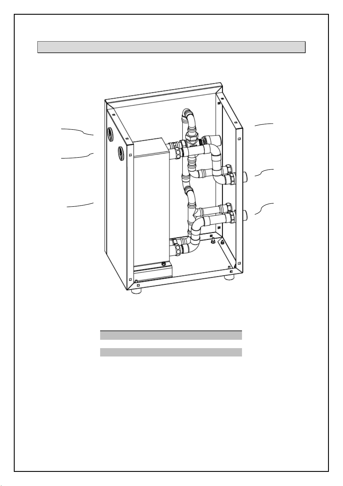
External heat recovery system AirWatt is intended for professional use. This user manual
provides all necessary information for dimensioning, installation, safe operation and
maintenance. It should be read thoroughly and carefully. Obey all safety instructions.
Manual should be conserved through entire lifetime of device. Regular and correct
maintenance and regular safety checks are required for long and trouble free operation.
Installation and use may be subject of local laws and directives which must be obeyed. For
any further information or in case of doubt contact manufacturer. Manufacturer will not be
held responsible for any defects, which are consequence of misinterpreting user manual
instructions, unprofessional installation or disobeying local laws and directives.
General safety instructions
Warning!
Operating this device may be dangerous, if following instructions are
not obeyed. In addition to this manual instructions from compressor
manufacturer must also be observed.
AirWatt unit was designed and manufactured in accordance with all health and safety
requirements of EU.
•All personnel involved at installation, operating and maintenance of this device must
reed and fully understand this included instructions.
•Installation and assembly of the unit can only be performed by authorized personnel
of company Omega Air d.o.o. Ljubljana.
•Device may only be used in accordance to this manual.
•Personnel must always wear personal protective equipment.
•Do not use this device, if there are present any signs of damage or defect.
•Always turn of compressor, lock the power supply and depressurize the system,
before performing any kind of work on device or installation.
•Device must have installed limiting elements, which prevent operating outside
specified parameters.
•It is forbidden to approach device under operation.
Installation and maintenance work on the device my only be carried by authorized and
trained professional.
•It is forbidden to alter the device or its construction in any way.
•Before maintenance depressurise the system.
•Use only original spare parts.
•Use the device only for the purpose for which it was originally designed.

AirWatt - Installation and operating manual
Field of use
External heat recovery unit AirWatt is intended for recapturing waste heat, which is
generated at air compression. Up to 70% of energy, consumed by compressor may be in
form of heat. Recovered heat may be used for heating domestic hot water or for central
heating. Recovered heat may represents significant savings and reduced load on
environment.
Principle of operation
AirWatt has two separate piping systems, through which flows water or oil. Device is
connected to oil circuit in compressor. Inside built in plate heat exchanger oil cools and
water gains heat.
Unit is regulated and protected with thermostatic valve, which maintains oil temperature
above set value. Correct oil temperature is crucial for safe and long operation of screw
compressor. Water does not start to flow, until oil temperature reaches set value. Switch on
temperature of thermostatic valve can be set between 60°C and 90°C. Device also has two
thermometers installed on housing to monitor inlet and outlet water temperature.
Heat recovery
There are four connections on the back side of device. Two are connected to compressor oil
circuit, the other two are for water circuit. When compressor is in operation, compressor oil
constantly flows through AirWatt heat exchanger oil piping and plate heat exchanger. Water
does not start to flow through thermostatic valve, until oil temperature reaches the set
value on the valve. When oil temperature reaches desired value, thermostatic valve opens
water flow through plate heat exchanger. Heat is extracted from oil and it’s temperature
drops. Water gains heat. The lower the water flow, the higher it’s temperature at outlet
gets.

AirWatt - Installation and operating manual
Connection
Place AirWatt on flat surface. Connect oil circuit and water installation on the device as
demonstrated on the picture below.
Oil circuit installation requires special interference with compressor construction. Only
authorized personnel are allowed to install the unit.
Connection of oil circuit:
-Must be performed by Omega Air or by authorized and trained professional.
-Compressor oil circuit is required.
-Establish pipe connection between compressor and AirWatt unit.
-Replenish oil in compressor separator to prescribed level. AirWatt and connecting
circuit between compressor has some volume and holds certain capacity of oil.
Connection of AirWatt will therefore lower oil level in compressor separator.
Connection of water circuit:
-Must be performed by plumber or heating systems installer.
-Connect water pipes to inlet and outlet connections.
-Install suitable water pump with option of flow regulation.

AirWatt - Installation and operating manual
Maintenance
•Once a month check the device for possible defects.
•All maintenance work must be performed by qualified and trained professional.
•Before any work on installation, turn of the compressor, lock the power supply and
depressurize the system. Turn off the water pipe.
•Use only original spare parts.
•From time to time clean the piping installation to prevent the clogging by debris.
•Cleaning intervals depends on water purity: 6 months for very dirty water; 1 year for
moderately polluted water; 3 years for relatively clean water.
•For cleaning oil sediment and grease it is recommended to use paraffin, for cleaning
limestone it is recommended to use acetic or citric acid.
Warranty exclusion
The guarantee shall be void if:
•The operating instructions were not followed with respect to initial commissioning
and maintenance.
•The unit was not operated properly and appropriately.
•The unit was operated when it was clearly defective.
•Non-original spare parts or replacement parts were used.
•The unit was not operated within the permissible technical parameters.
•Unauthorised constructional changes were made to the unit or if parts of the unit
that may not be opened were dismantled.

AirWatt - Installation and operating manual
Settings
Change of target temperature
1. In order to change the target flow temperature, press the left or right button (A)
2. Press the middle button shortly to confirm new target temperature (B).
Advanced Settings:
1. Press middle button for 5 seconds to reach advanced settings (A).
2. To move between menus press left or right button (B).
3. Press middle button (OK) to enter desired menu (C).

AirWatt - Installation and operating manual
Maximum Flow Temperature
1. To change the maximum flow temperature press middle button the joystick for 5 seconds to reach
advanced settings.
2. Choose menu “Max” by pressing the middle button OK.
3. Decide the maximum flow temperature by pressing the left or right button OK.
4. Press down the middle button for 5 seconds to return to main menu.
Minimum Flow Temperature
1. To change the minimum flow temperature press the middle button for 5 seconds to reach
advanced settings.
2. Choose menu “Min” by pressing left or right button OK.
3. Decide the minimum flow temperature by pressing the left or right button OK.
4. Press the middle button for 5 seconds to return to main menu.
Table of contents