1
Heat & Glo • PHFR-PRIMO-48, PHFR-PRIMO-60, PHSI-PRIMO Instructions • 2560-970 Rev. D • 2/19
PRIMO Passive Heat PowerFlow™ Heat Management System
Passive Heat - Front Discharge: PHFR-PRIMO-48, PHFR-PRIMO-60
Passive Heat - Side Discharge or Open Top Discharge: PHSI-PRIMO
Models: PRIMO48, PRIMO48ST, PRIMO60, PRIMO60ST
Installation Instructions
Leave this manual with party responsible for use
and operation.
CAUTION! Risk of Cuts, Abrasions or Flying Debris.
Wear protective gloves and safety glasses during instal-
lation. Sheet metal edges are sharp.
DANGER
HOT GLASS WILL
CAUSE BURNS.
DO NOT TOUCH GLASS
UNTIL COOLED.
NEVER ALLOW CHILDREN
TO TOUCH GLASS.
A barrier designed to reduce the risk of
burns from the hot viewing glass is provided
with this appliance and shall be installed for
the protection of children and other at-risk
individuals.
CAUTION! Do not install damaged components.
This appliance comes standard with patented
SafeSurfaceTM Glass which keeps the surface temperature
of the barrier glass at a safe level and will still be hot to
the touch when operated for long periods of time.
If the barrier glass is removed, the inner glass temperature
will be very hot and cause burns.
WARNING! Risk of Fire!
• Combustible materials MUST NOT overlap or be placed
behind a decorative front.
• DO NOT apply combustible materials beyond the
minimum clearances. Comply with all minimum
clearances to combustibles as specied. Overlapping
materials could ignite and will interfere with proper
operation of decorative fronts.
If any parts are missing or damaged, contact your dealer before
starting installation. DO NOT install a damaged kit.
Table of Contents
1. Introduction ....................................2
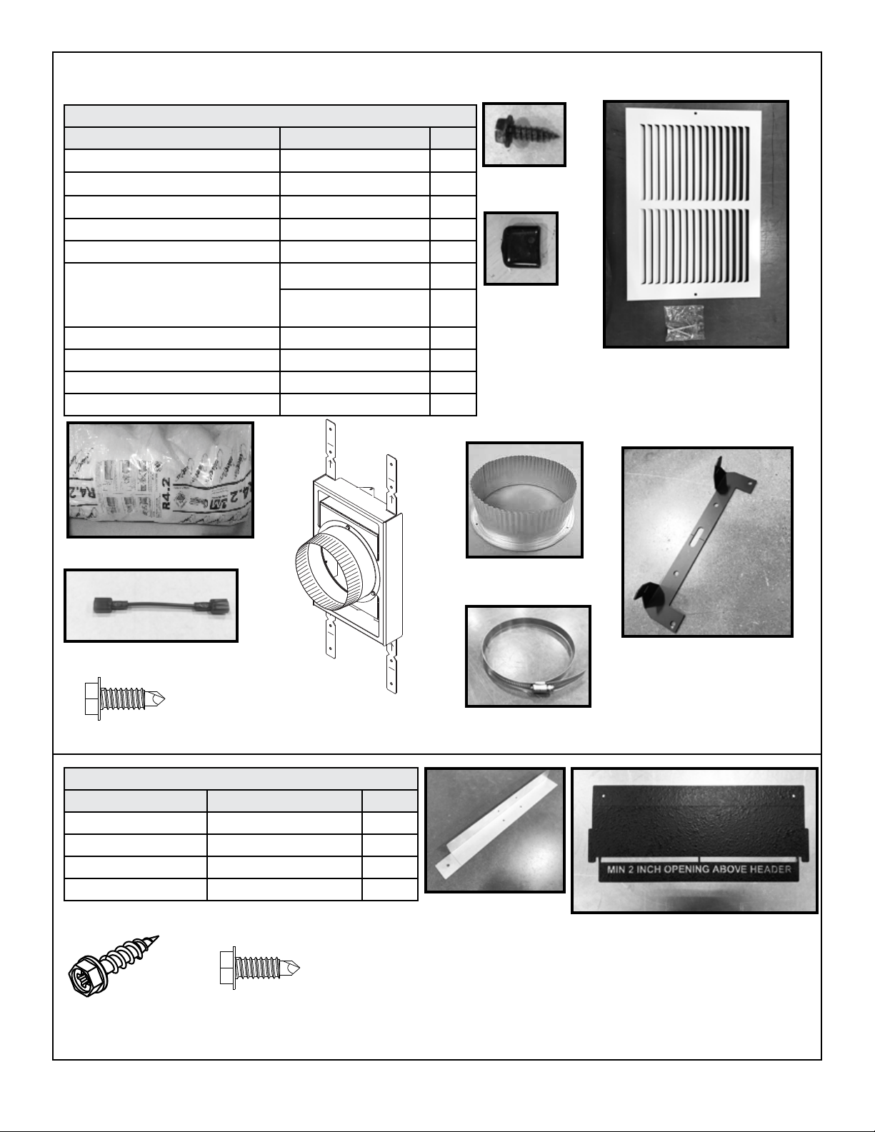
2. Kit Contents....................................3
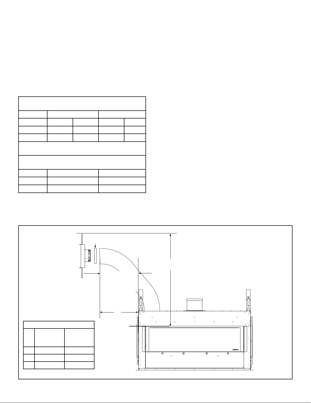
3. Preparation ....................................5
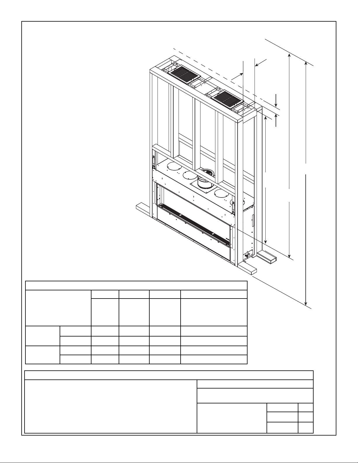
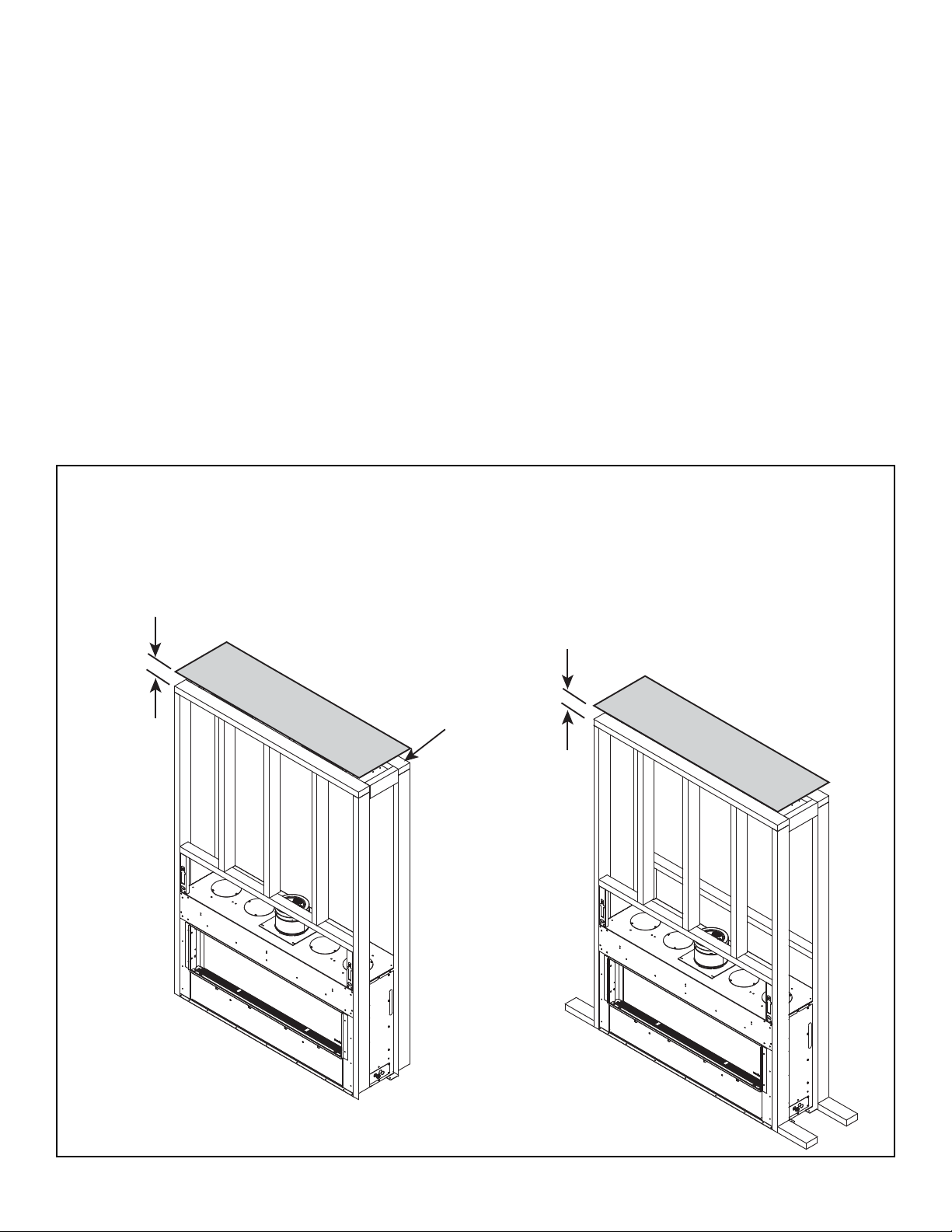
4. Framing ......................................6
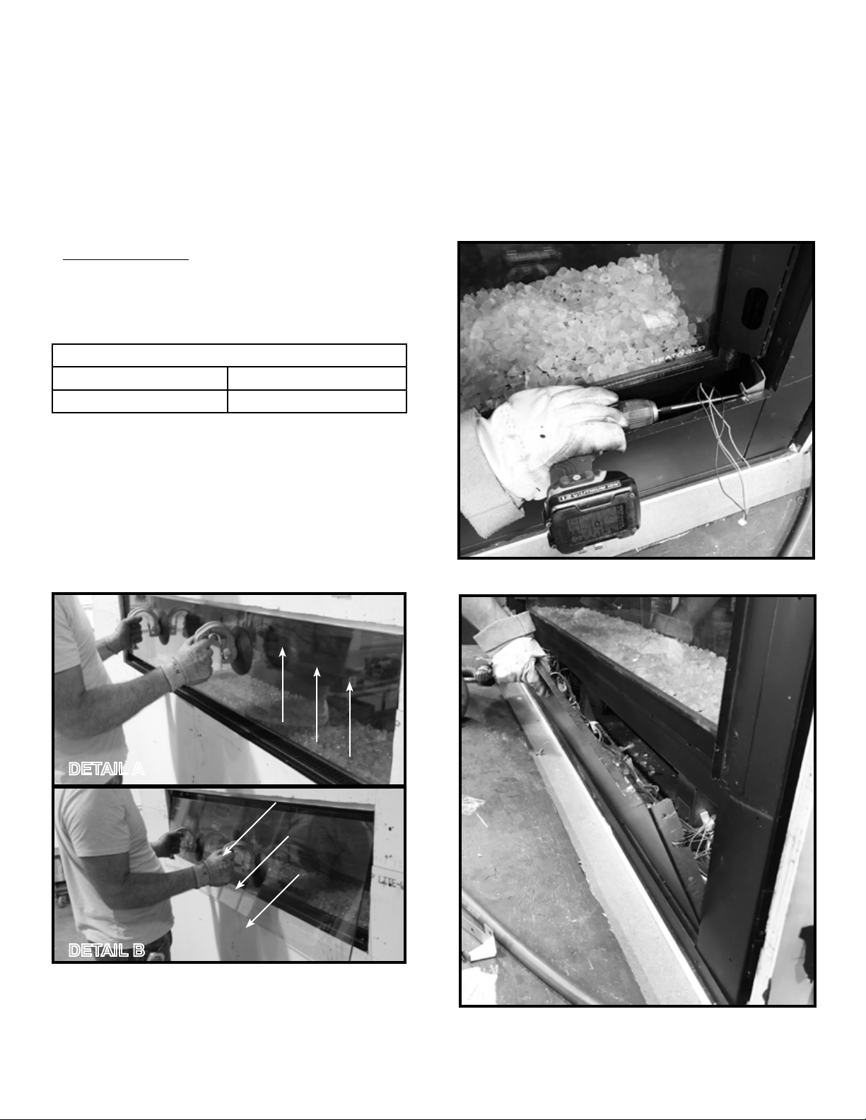
5. Remove Barrier Glass/Bypass Limit Switch and
Glass Mounting Brackets .........................9
6. Installation and Finishing - Front Discharge ..........14
7. Installation and Finishing - Side Discharge ...........20
8. Installation and Finishing - Open Top Discharge .......24
9. Wiring Requirements............................31
10. Maintenance ..................................33