Omega Vehicle Security Freedom-450 User manual

COPYRIGHT:OMEGARESEARCH&DEVELOPMENT2007
Owner's Guide
COVER PROVIDED IN
SEPARATE FILE
FrFr
FrFr
Freedom-450eedom-450
eedom-450eedom-450
eedom-450


Introduction
Page 3
Congratulations on the purchase of your Freedom-450 vehicle security system.
It is most important to note that the Freedom-450 has a unique and flexible
design, which allows the system to be installed in several configurations, or lev-
els of sophistication, and thus affects the total operations. The exact operations
of your system reflect this, and therefore it is most important that this operations
guidebecarefullyreadandreferredto. Regardlessofhowconfigured,you’llfind
your system both easy to operate and reassuring in its effective theft deterrence
capabilities.
Some principle components to become familiar with:
The Transmitter: Regardlessofhowthesystemisconfigured,theremotetrans-
mitter is used to operate the system. Two transmitters can operate the system,
and two are supplied with the system already programmed to operate it.
Everytransmitterhasitsownunique,invisiblecode,andthuscannotbeduplicated.
The transmitter has four buttons: an “Arm” button, a “Disarm” button and button
3 which can be used, if desired, to arm and disarm your system silently, and to
bypass the built-in shock sensor. The “Arm” and “Disarm” buttons also operate
the Remote Panic feature. Button 3 is also used in transmitter and features’
programming operations. Button 4 Can be used with optional Rec-43 to operate
an auxillary channel.
MO_FREEDOM-450 / REV0 11/
07
Page 22
Replacement Transmitters
Replacement or optional transmitters are readily available from the dealer from
which you purchased your system; or may purchased directly from Omega
ResearchandDevelopment. TransmitterspurchasedfromOmegaare$40.00
eachplusshippingfees. The proper transmitter foryourFreedom-450systemis
Omega’spartnumber#4412-09;oranyOmegatransmittermaybeidentifiedand
viewed on the Internet at “www.caralarm.com”.
TransmittersmaybeorderedfromOmega directlyby sendinganotetothebelow
address with the desired transmitter’s part number (#4412-09 for the Freedom-
450), a legible return address, and remittance of $ 40.00 plus shipping fees for
eachtransmitterorderedintheformofpersonalcheck,moneyorderorcreditcard
information. Mail these to:
Omega Research and Development, Inc.
P. O. Box 508
Douglasville, Georgia 30133

Page 4
“Quick Reference” of Transmitter Functions
The “Arm” Button
Pressing and releasing
the Arm Button will arm
the system. Pressing
and holding this button
3 seconds will activate
Remote Panic which
will leave the system
armed when stopped.
Blue Light
Illuminateswhenever any transmitter buttonispressed.
The “Disarm” Button
Pressing and releasing the
Disarm Button will disarm
thesystem. Pressing and
holding this button 3
seconds will activate
Remote Panic which will
leave the system armed.
Your system can be operated by
two transmitters. Replacement
transmitters,ifneeded, areavail-
able from where you purchased
your system, or from Omega-
see page 22.
Button 3
Pressing and releasing the
Small Button two times will
arm or disarm the system
withoutchirps. Uponarming,
pressing and releasing this
buttonwillturnoffthebuilt-in
shock sensor.
Button 4
Can be used with
optional Rec-43 to
operate an auxillary
channel
Page 21
Step 1: After ensuring the system’sBluewireisnon-grounded,removeandthen
restore power to the system. The siren will chirp once, and the parking
lights, if connected, will flash 6 times.
Step 2: Immediately upon the single siren chirp, press and release
Button 3 on the first transmitter. The system will respond with one chirp.
Step 3: Within 6 seconds, press and release Button 3 on the second
transmitter to be programmed. The response will be one, then another
chirp, which indicates both transmitters have been programmed, and the
system is exiting Transmitter Programming Mode.
Shouldonlyone transmitter be programmed, after 6 seconds of no programming
activity the system will sound two chirps and automatically exit Transmitter Pro-
gramming Mode. Also, if only one transmitter is programmed, one preexisting
transmitter code will be retained. Should it be desired to purge the preexisting
code, simply program the single new transmitter twice into the system.
by unplugging, then plugged back together, the system’s 9-wire harness, or by
removing and then restoring the Blue 15 Amp fuse on the system’s Red main
power wire, which is also located at the control unit and siren assembly. The
Freedom-450 may be operated by up to two transmitters.

TheStatusIndicatorLightandtheLEDStatusIndicatorLightaresuppliedwiththe
Freedom-450 system kit, but are not absolutely necessary for the system’s
operation. Therefore, these items may or may not be present with your system.
Mostimortantly,consultwiththeinstaller;iftheValet/OverrideSwitchisinstalled,
as to the location of this switch.
The Valet/Override Switch: This switch can be used to turn “Off” the alarm
portionofthesystem,byplacingthesysteminto“ValetMode”.TheValet/Override
Switch can also be used in conjunction with the vehicle’s ignition key to perform
an“Emergency Override”ofthesystemshouldthetransmitter belostor become
inoperable. Bothoftheseoperationsareexplainedonpages13-16,andasnoted
above this switch may or may not be present with your system.
The LED Status Indicator Light: The LED Indicator shows the status of the
system and serves as a visual deterrent to break-ins and theft. See page 16 for
a detailed description of the Status Indicator Light’s operations, and as noted at
top of this page, this light is not necessary for the system’s operations, and may
or may not be present with your system.
Bothofthe above itemsmaybelocatedin a specialcombinationholder,whichis
supplied with the Freedom-450 system kit.
Page 5Page 20
Step 5: If programming multiple features, once the first feature has been config-
ured and acknowledged by 1 or 2 chirps, select the next feature by re-
peating Step 3 and Step 4.
Step 6:Onceallof the selected features have beenprogrammed as desired, the
system may removed from Features Programming Mode by allowing it
time to out via 10 seconds of no programming activity, or by pressing
and holding the Transmitter Button3 for 4 seconds. Regardless of
method,thesystem’sexit from Features Programming Mode is indicated
by 3 long siren chirps.
How to Program Transmitters to the System
Whenever the Freedom-450 is powered up, it automatically enters a Transmitter
Programming Mode. If the hood detection circuit (this is a Blue wire) is con-
nected, this wire must be in a “non-grounded” state when the system is powered
upinorder for it to enterTransmitterProgramming Mode. Where this applicable,
simply hold the hood detection switch down, or temporarily disconnect it. “Pow-
eringup”the system willentailfirst removing, and thenrestoringpowerand ground
to the system’s control module and siren assembly. This is easily accomplished

THE SIREN WILL
CHIRP ONCE THE PARKING LIGHTS
WILL FLASH ONCE
(IF CONNECTED)
UponArming: • The siren will chirp one time.
• If connected, the parking lights will flash once.
• The optional starter interrupt, if installed, will engage.
• If installed, the Status Indicator Light will begin to flash slowly.
• Another option is having the doors automatically lock when-
ever the system is armed. This requires connecting an opt-
ional interface (the Omega “DM-1”).
“Arming”placesthesystemintoastatewherebyitwillrespond,or“activate”toany
detectedintrusionattempt. ThesystemmaybeArmedprovidedtheignitionswitch
is "off" and the system is not in Valet Mode.
To Arm the System: Press & Release the Transmitter’s
“Arm” Button.
Arming the System
Page 6 Page 19
Step 1: The system must be connected to power and ground, and be disarmed.
Step 2: Press and hold either transmitter’s “Disarm” and button 3 together
for 4 seconds; the system will chirp 5 times confirming entry to Features
Programming Mode.
Step 3: Within 10 seconds of entering Features Programming Mode, press and
release the transmitter’s Button 3 the number same of times that
equals the number of the feature to be programmed. After a pause, the
system will repeat the feature number with a like number of siren chirps.
Step 4: After the system acknowledges the feature to be programmed, press
eitherthe “Arm” Button to turn the feature on(thesystem’sresponse will
be 1 chirp), or the “Disarm” Button to turn the feature off (the system’s
response will be 2 chirps).
How to Program Features
The 6 programmable features, described on the previous two pages, are very
easily programmed by the following procedure:

Once Armed, If the System is Activated:
Page 7
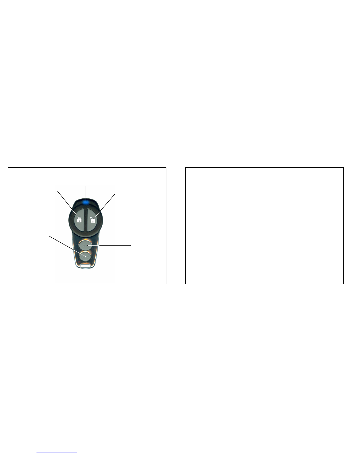
System Armed & Activated
Once the system is in an armed state it monitors all protected zones, and if an
intrusion attempt is detected it will activate, or “trigger”.
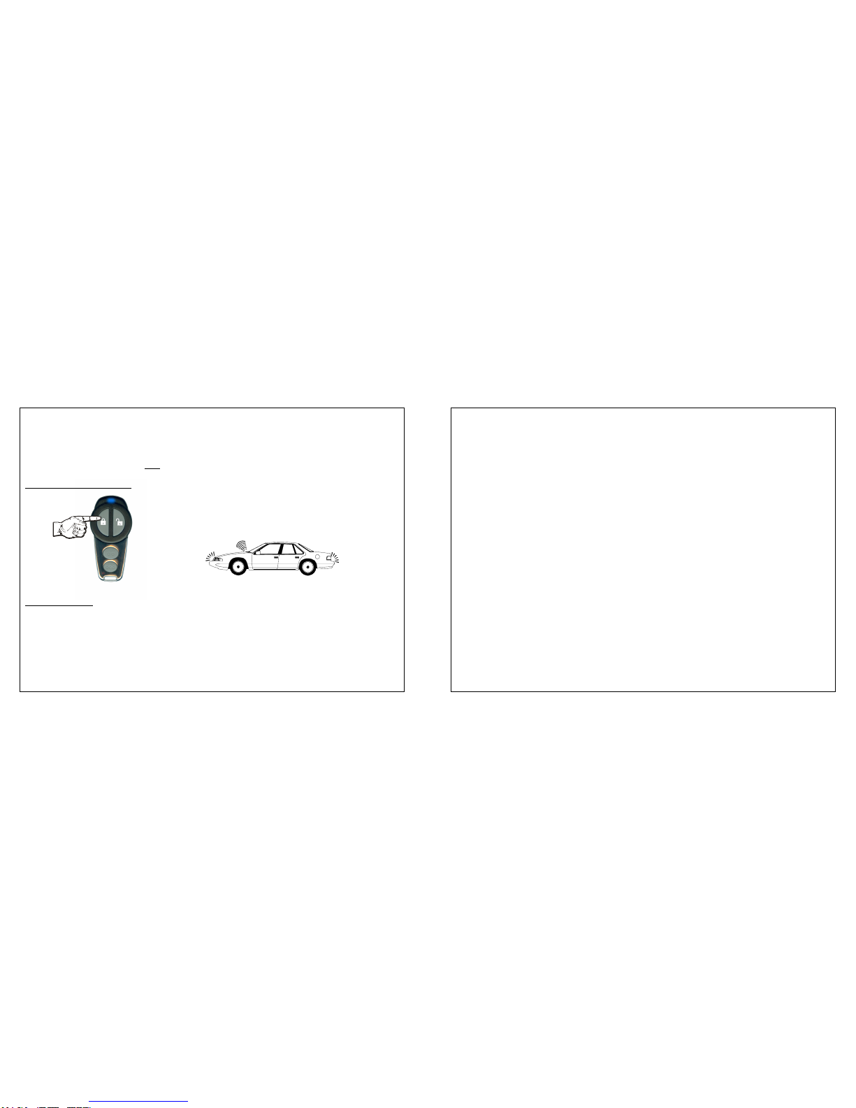
An activation consists of the following:
• The siren will start sounding.
• The exterior parking lights, if connected, will flash on and off repeatedly.
An activation has a 30 second duration (or, optionally 60 seconds) unless the
system is disarmed using the transmitter or the Valet/Override switch. If all
protected zones are secure at the end of the activation, the system will stop and
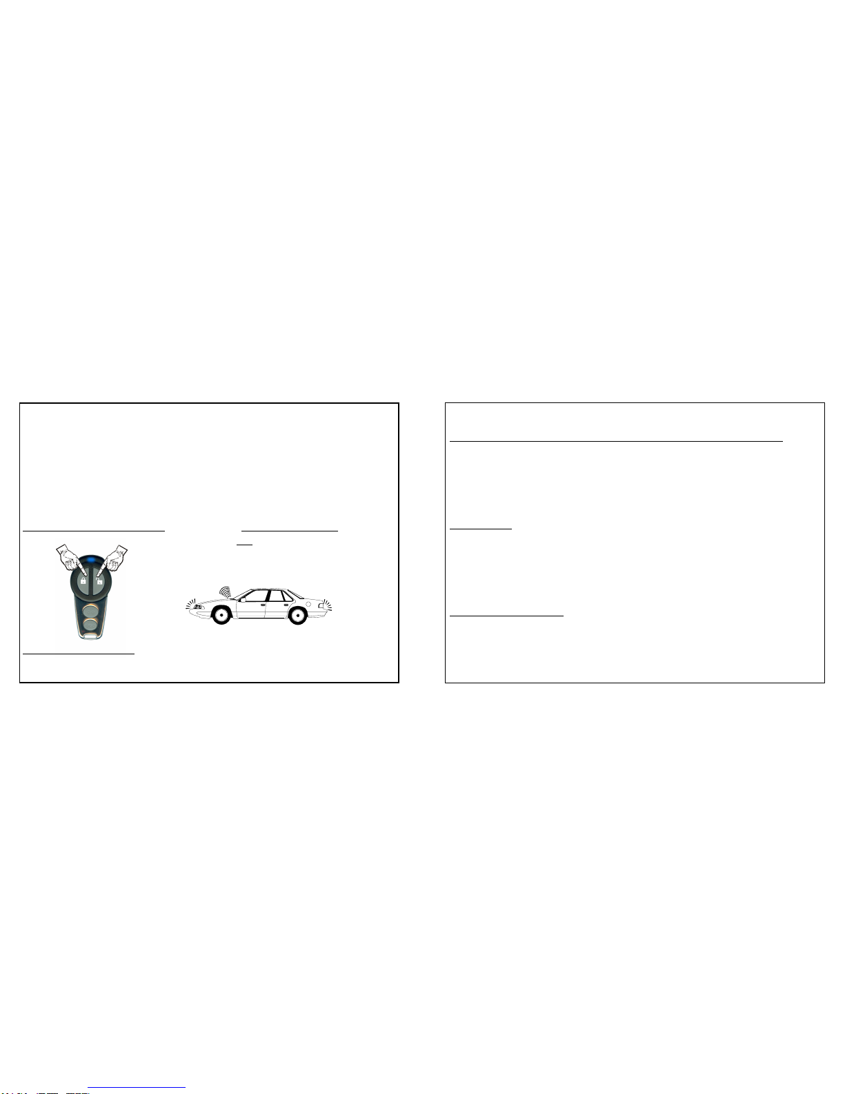
In addition to detecting impacts to the vehicle and detecting a current draw from
thebattery(example- interior light illuminating from opened door), theFreedom-
450 has a detection circuit which may be used to protect the hood, trunk or
doors. If this circuit is in a violated state when arming the system, the confirma-
tionwillbethreechirpsinstead ofone. Thesystemwillstillarm,butit will bypass
the open zone until the zone is secured; once secured, this zone is protected.
mode, and chirps made during the programming of features or transmitters.
4. Parking Light Illumination Upon Disarming: (On / •Off)
- This feature configures the system, upon its disarming, to either flash the
parking lights 2 times, or to flash the parking lights twice and then turn them
onfor30seconds. Thisfeature makes it safer to approach the vehicle when
disarming it at night by illuminating the area around the vehicle.
5. System Activation Cycle Duration: (•30 / 60 Seconds)
- Thisfeatureconfigures the system’s activationcycletobe either 30 seconds
or 60 seconds in duration before it automatically resets itself.
6. Shock Sensor Prewarning On or Off: (•On / Off)
- This feature turns on or off the prewarning only part of the shock sensor
operation. If prewarning is turned off, the “hard impact” part of the shock
sensor is still fully operable.
Whenprogrammingthesefeatures,asdescribedonthefollowingpages,features
areturned“on”bypressingthetransmitter’s“Arm”Button,and“off”bypressingthe
transmitter’s “Disarm” Button. For feature #2, press “Arm” for “3 Seconds”,
“Disarm” for “3 Minutes”; and on feature #5 press “Arm” for “30 Seconds”, and
“Disarm” for “60 Seconds”. Please see the following pages for more details.
Page 18

rearm itself to detect further entry attempts. If a protected zone is still open at the
endoftheactivationcycle,thesystemwillcontinuetoreactivateitself,foruptosix
activated cycles before it resets itself and ignores the violated zone.
Page 8
THE SIREN WILL
CHIRP TWICE THE PARKING LIGHTS
WILL FLASH TWICE
(IF CONNECTED)
To Disarm the System: Press & Release the Transmitter‘s
“Disarm” Button.
Disarming the System
Upon Disarming: • The siren will chirp twice (or 4 times if alarm has activated)
• The parking lights, if connected, will flash twice.
• The optional starter interrupt, if installed, will disengage.
• If installed, the Status Indicator Light will turn “Off”, or, it will
change to flashing rapidly if the system was activated, and Page 17
Programmable Features
The Freedom-450 vehicle security system has 6 programmable features which
allowthesystemtobecustomized. Thefollowingpagesprovideabriefexplanation
foreachfeature,andnotesitsfactorydefaultsetting. Followingthesedescriptions
are instructions on how to program the features.
• = Default Factory Setting
1. Current Sensing: (•On / Off)
- This feature enables the armed system to be activated should the system
detect a voltage spike or current draw in the vehicle’s electrical system.
2. Current Sensing Activation Delay: (•3 Seconds / 3 Minutes)
- Allows the option of a longer delay before activation by current sensing can
occur. Thisisforuseinvehicleswithequipment,suchascoolingfans,which
stayson for a short period of time after the ignition has been turned off.
3. Confirmation Chirp: (•On / Off)
- This feature allows the arming and disarming confirmation chirps to be
permanentlyturnedoff. Whenthesechirpsareturnedoff,exceptionswillbe
the prewarning chirps, the chirp made when the system is placed into valet

Press &
Release
Twice
X 2
Page 9
then reset itself.
• If the optional DM-1 doorlock interface was installed, the
doors will also unlock upon disarming.
Should you wish to arm or disarm the system without
the confirmation chirps, simply press and release the
Transmitter Button 3 twice. Using the Silent Arm/
Disarmoperationsimplyreversesthearmed/disarmed
statusofthesecuritysystem-if thesystemisdisarmed
when the double Button 3 signal is received, it arms;
shouldthesystembearmedwhenthedoublesignalis
received, it will disarm.
Silent Arming & Disarming
To Silently Arm / Disarm: Press & Release the Transmitter’s Small
Button Twice
Should the transmitter be lost, damaged, or its batteries be exhausted, the Valet
/Override Switch & your vehicle’s ignition key may be used to disarm the system
by performing an Emergency Override, which is explained on pages 15-16.
Page 16
WhentheValet/OverrideSwitchispressed,andthesystemdisarms,releasingthe
switchwillplace thesysteminstandby mode. Toputthesystem into valetmode,
simply press the switch and hold it for 3 seconds.
Step 3: Within 5 seconds, Press the Valet/Override Switch.
-The activated system will instantly disarm.
The Status Indicator Light
The Status Indicator Light visually shows the status of the system and also
provides a high level of visual deterrence. The Status Indicator Light can be
mounted in the holder with the Valet/Override Switch, or mounted in a location
where it can be easily seen by the driver, as well as from outside the vehicle.
Status Indicator Light Off = The system is disarmed and in standby mode.
Status Indicator Light Flashing Slow = The system is armed.
Status Indicator Light Flashing Fast = The system has been activated.
Status Indicator Light On Solid = The system is in the valet mode.

Page 10
Should you feel threatened or in need of attracting attention, the system can be
activated remotely by using the transmitter. Your system features “Enhanced
Panic”,whichallowsyouto activate Remote Panic from either the “Arm” button or
the“Disarm”button. The former leaves the system armed when Remote Panic is
turned off, and the latter leaves the system disarmed when Remote Panic is
turned off.
Remote Panic Operation
To Activate Remote Panic: Press & Hold for 3 Seconds the “Arm”
Button OR the “Disarm” Button
Hold 3
seconds
Hold 3
seconds
OR
THE PARKING LIGHTS
WILL FLASH ON & OFF
(IF CONNECTED)
THE SIREN WILL
SOUND
Upon Activating Panic:
• The siren will sound.
• If connected, the vehicle’s exterior parking lights will flash on and off. Page 15
If the system is armed, and in the event that the transmitter is lost, damaged, or
itsbatterieshavebecome exhausted, the Valet/OverrideSwitch&your vehicle’s
ignition key may be used to disarm the system by performing an Emergency
Override.
EMERGENCY OVERRIDE-
How to Disarm the Security System Without the Transmitter:
Emergency Override:
Step 1: Withthesysteminthearmedcondition,enterthevehicleviathedriver's
door (be aware that the alarm will likely activate when the door is opened).
Step 2: Using your key, turn the vehicle’s ignition to the "On" position.
IMPORTANT: in addition to the inclusion of the Valet/Override and Status
Indicator Light, the Freedom-450’s “ignition input” wire must also be connected.
IftheFreedom-450wasnotinstalledwiththeValet/OverrideSwitch,ortheignition
input being connected, the only way to bypass, or turn off the system is to locate
and unplug the control module and siren assembly must be unplugged from its
wiring harness!

Remote Panic can be activated anytime, whether the vehicle’s ignition is turned
on or off, and has a 60 second duration (regardless of the 30 or 60 second acti-
vation setting) unless a transmitter is used to stop it.At the end of the 60 second
cycle,thesystem will reset and be in either the armed state (if Remote Panic was
activated by the “Arm” button) or in the disarmed state (if Remote Panic was
activated by “Disarm”).
Page 11
To Deactivate Remote Panic: Press & Release either the “Arm”
Button OR the “Disarm” Button
Once Remote Panic has been activated, rather than wait for the system to stop
automatically at 60 seconds, the transmitter may be used to stop the Remote
Panic operation. Simply press and release the “Arm” or “Disarm” button. While
pressing either of these buttons will stop the Remote Panic operation, please
note that the system’s armed or disarmed status will depend upon which button
was used to activate the Remote Panic in the first place. For example, if the
“Arm”buttonwas pressed and held to activate Remote Panic,andifthe “Disarm”
buttonwasusedto stop it, the system will revert to the armed state when Remote
Panic is stopped, because the “Arm” button was the one used to activate the
operation.
Valet Mode prevents the system from becoming armed. Valet Mode is designed
forsituationsinwhichitisnot convenient for the alarm portion of the system to be
operational;forexample,suchaswhenloaningothersyourvehicle,orleavingthe
vehicle for servicing, maintenance, valet parking, washing, etc.
Page 14
To Enter Valet Mode: Press & Hold the Valet
(System MUST be Disarmed) Switch for 3 Seconds
- The Status Indicator Light will turn on solid Red and the siren will chirp once to
confirm Valet Mode. Now the system cannot become armed.
To Exit Valet Mode:Simply Press & Release the
Valet Switch.
- The Status Indicator Light will turn off to confirm that the system has exited
Valet Mode and returned to a“standby”mode. Normalarmingoperationsmay
be resumed.
The security system must be disarmed, and the vehicle's ignition may be "On" or
"Off" when entering or exiting Valet Mode. If the system is armed, or activated, if
the transmitter is lost or inoperable an Emergency Override must be performed!

Page 12
The Freedom-450 vehicle security system is equipped with a built-in “shock”
sensor which detects impact to the vehicle. As vehicles differ structurally, and
mountinglocations of the system control modulevary, this shock sensor is easily
adjustable. Theshocksensoradjustmentisfoundontherearofthecontrolmodule
and siren assembly, below a weatherproofing rubber cover plug. Turning the
adjustment clockwise increases sensitivity, and turning the adjustment counter
clockwise decreases the sensor’s sensitivity. If adjustments are made to the
sensor, the rubber plug must always be replaced.
Shock Sensor & Prewarning
Bypassing the Auxiliary Sensor: If desired, the system may be armed, but
without the auxiliary sensor being part of the system’s protection. Upon arming,
immediately after the single arming confirmation chirp, simply press and release
the Transmitter’s Small Button; the system will chirp the siren once again to
confirmthatthesensor is bypassed. When the sensor hasbeenbypassed,itwill
not activate the alarm, nor will it have the prewarning operation.
PrewarningDetection:Theshocksensorcircuitfeatures“prewarning”operation.
Whenthesecuritysystemdetectsalightimpactthroughthesensor,itwillrespond
chirping three times, whereas a heavy or sharper impact will fully activate the
system,soundingthesirenandflashingtheparkinglights,iftheseareconnected.
Page 13
To Bypass Shock Sensor: Press & Release the “Arm” Button THEN
Press & release
“button 3” (1 more
chirp is heard- the
shock
Press &
release
the “Arm”
button
(1 chirp is
FIRST THEN THE PARKING LIGHTS
WILL FLASH ONCE
UPON ARMING
FIRST: THE SIREN WILL CHIRP
SECOND: THE SIREN WILL
CHIRP
ONCE AGAIN INDICATING
Valet Mode & Emergency Override
As noted in the “Introduction” section of this booklet, the Valet/Override Switch is
not essential, but its inclusion offers several convenience benefits. The Valet/
Override Switch can perform two distinct functions: accessing Valet Mode and
performing an Emergency Override of an armed and activated system. It is
important that you know the location of the Valet Switch; a Valet Switch and LED
StatusIndicatorcombinationholderisprovidedwiththeFreedom-450kit,andmay
have been installed. If the Valet/Override Switch is used, the Status Indicator
Light’suseis also highly recommended, as it shows the presence of ValetMode.

Installation Insert Page 1
Mounting the Control Unit and SirenAssembly: Find a location in the engine
compartment away from the extreme heat of the engine and manifolds. A suit-
able location will offer a firm mounting surface, will also allow sound dispersion
out of the engine compartment, and not be accessible to a thief.The control unit
andsirenassemblymustbepointeddownwardtoavoidmoisturecollectinginthe
unit and to enhance sound dispersal. The unit's wires should be securely con-
nected to the appropriate vehicle wires with the proper terminals, connectors, or
by soldering and tape or heat shrink tubing for insulation. Wires routed through
panels such as the firewall should always be protected by an existing or added
grommet.A vehicle security system is also more effective if its wiring is wrapped
or enclosed in a protective sleeve which matches that already found in the ve-
hicle protecting the factory wiring.
Installation
Please Note- the center section of this booklet
consists of complete Installation Instructions for
your Freedom-450 security and convenience
system. If desired, these pages may be removed,
leaving only the Owner’s Guide booklet.
Installation Insert Page 12
ifthealarmisarmed (including while the alarm is activated),andwilldrawcurrent
from the vehicle's electrical system only if an attempt is made to start the vehicle.
CONNECTION: To interrupt the vehicle's starter circuit, the starter wire must be
located and cut. It is recommended that this connection be done as close to the
ignitionswitchaspossible. Useavoltmeter,notatestlight, tofindthecorrectwire,
whichisthewire fromtheignitionswitchtothestartersolenoid. CAUTION!Avoid
theairbag circuit!Improperuse ofatest lightcancausedeploymentoftheairbag,
whichmayresultinbodilyinjury! Testlightscanalsodamageon-boardcomputers
andassociated sensors. Thestarterwirewillread+12Voltsonlywhenignitionkey
is in "start" position (cranking the engine). Cut this wire at a suitable location.
Confirm that this is the correct wire by turning the ignition switch to the "start"
position. The starter should not engage.
Relay
Optional
Starter
Interrupt Orange / Orange
✄
White:
To Starter
Red: To
Ignition
Switch
Cut wire
Freedom-450
Control Unit and
Siren Assembly
Starter
Ignition
Switch

Wiring Connections
Afterthecontrolunitand siren assemblyhasbeenmounted,follow the instructions
for each wire's connection. Please note that during the initial installation, as
soon as the Black ground wire and Red Constant power wire have been
connected, the system will enter Transmitter Programming Mode, which is
explainedonPages20-21. Asthe included transmitters are already programmed
at the factory, no action is needed, and simply allow Transmitter Programming
Mode to automatically time itself out after 6 seconds.
Installation Insert Page 2
The Freedom-450 is a uniquely engineered design; it can be installed and have
basicoperationswiththeconnectionofonlytwoofit’sninewires. Theconnection
andutilizationofitsremainingwiresgreatlyaddstotheoperationalsophistication
of this system, and it also features two independent parking light wires.
Ofthesystem’snine wires, the Red, Black, twoWhites,andYellowwiresinmost
cases can be connected within the engine compartment. The Blue wire, if it is
connected to a hoop pin switch only, will also remain within the engine compart-
ment. Ifitis to also be connected to a trunk pin switch,orpossiblythedome light
circuit to protect the doors, will need to be routed into the vehicle interior through
the firewall. The Gray, Pink and Orange wires will need to be routed through the
firewall and into the vehicle interior. Installation Insert Page 11
Orange Wire - (Negative Output For Optional Starter Interrupt): TheOrange
wire is for an optional starter disable socket and relay, and/or an optional DM-1
powerdoorlockinterface(whichincludesitsowninstructions). Thefunctionofthis
wireistoprovide a500mA-GroundOutputwheneverthe securitysystemisinan
armed state. In the starter interrupt application, this output supplies - Ground to
onesideoftherelay'scoil. Theothersideoftherelaycoilwillbesuppliedwith+12
Volts from the ignition switch, but only if the ignition switch is turned to the "start"
position. Ifthis occurs,thecoil willenergize,activatingtherelay,whichinturnwill
openthestartercircuit. Thestarterinterruptpreventsthevehiclefromstartingonly
Status Indicator Light: Mount the Status Indicator Light using the combination
holder,oritmaybemountedintoaninteriorpanelbydrillinga17/64”(6.5mm)hole.
The control module and siren assembly’s Pink wire must be routed to the Status
Indicator Light’s mounting location.
Once the Gray and Pink wires are connected, ground both of the devices’ Black
wiresusing thesuppliedringterminal. Mountthe combinationinalocationwhere
itcaneasilybeseenbythedriver,andpreferablywhereitcanbeseenfromoutside,
astheLEDStatusLightprovidesalevelofvisualdeterrence. Thelocationshould
also be easily accessible to the driver should the need arise to perform an
Emergency Override. Show the user the Valet/Override Switch location.

Installation Insert Page 3
1234
1234
1234
1234
1234
PINK WIRE - Positive Output for
LED
BLUE WIRE - Negative Instant Trigger
RED WIRE - Constant 12 Volts Positive
WHITE WIRES - Output To Parking Lights
BLACK WIRE -
Connect To Ground
ORANGE WIRE - Ground Output While Armed
BLACK ANTENNA WIRE-
Do Not Connect To Anything
- Stretch Out and Secure
GRAY WIRE - Valet/Override Switch
12345
12345
12345
12345
12345
Wiring Diagram
Shock
Sensor
Adjust
See Installation Insert Page 10 for
combination holder instructions
YELLOW WIRE -
Ignition 12
Volts Positive
Relay
Optional
Starter
Interrupt
Ground
both
Black
wires
Installation Insert Page 10
Although the Freedom-450 can have basic operations without them, the Valet/
OverrideSwitchandtheStatusIndicatorLightgreatlyenhance the system. The
Valet/Override Switch allows disarming the system without the transmitter and
placingthesystemintoa state in which it cannot be armed. TheStatusIndicator
Light visually and quickly shows in which state the system is in.
Valet/Override Switch: Use the combination holder, or otherwise use the self-
adhesive pad to mount the Valet/Override Switch in a hidden but accessible
location. The control module and siren assembly’s Gray wire must be routed to
the Valet/Override Switch’s mounting location.
Snap the combination holder bot-
tom half to the upper half; ensure
that the wires are routed carefully.
The upper half of the combination
holder may be mounted with the
two screws provided, or, double-
sided adhesive tape
may be used.
Then, when the upper half holder
is secured, insert the LED and
mount the Valet/Override Switch
using its double-sided adhesive
tape.
☞
LED Valet/Override
Switch

BlackWire- (- Ground Input): This wire’sconnectionisrequired for operation.
TheBlackwire'sfunction istosupply-Ground,whichcompletesthecircuitry and
allows the security system to operate.
CONNECTION:Usingitsringterminal,connecttheBlackwiretothemetalframe
ofthevehicle,preferablyusinganexistingmachine-threadedfastener. Makesure
that the ring terminal attached to the Black wire has contact with bright, clean
metal. If necessary, scrape any paint, rust or grease away from the connection
point until the metal is bright and clean. If the control module has an insufficient
groundconnection,thesecurity system can find partialgroundthroughthewires
thatare connectedtoothercircuits,butthealarmwillnotfunctioncorrectly,giving
the impression of a defective control module. The system can partially operate,
so a bad ground wire connection would be suspected. In some cases the alarm
could arm and disarm properly -but not function correctly otherwise.
Wiring Connections
Installation Insert Page 4
IMPORTANT: The Black wire attached to the control module and siren
assembly is the antenna wire. Do not connect this wire to anything or the
transmitter's range will be reduced or eliminated. Stretch theBlackantenna
wire out and as high as possible for the best operating range.
Installation Insert Page 9
the security system. Connecting this wire will prevent the system from being
armed while the ignition switch is on, and its connection is required if the Valet/
Overrideisinstalledforthepurposeofallowingthesystemtobedisarmedwithout
the transmitter (an “Emergency Override”).
CONNECTION: This connection should be made to the primary ignition circuit.
Primary ignition has 0 Volts when the ignition key is in the "Lock", "Off" and
"Accessory"positions;and+12Voltsinthe"Run"and"Start"positions. Makethis
connection at the engine compartment fuse/junction block, or (less desirable),
locate the correct wire at the ignition system and securely splice the Yellow wire
to it. Another option is to carefully route this wire through the firewall, and make
the connection at the ignition switch wiring harness, being sure to test the target
wire as described at the beginning of this section.
Gray Wire - (Valet/Override Switch Input): This wire is a- Negative input, and
connectstotheValet/OverrideSwitch. ThiswireandthePinkwirearesomewhat
related in function, and also related in routing and connection.
PinkWire- (Status Indicator LightOutput): Thiswire is aPositiveoutput,and
connects to the Status Indicator Light. This wire and the Pink wire are to routed
from the control unit and siren assembly into the vehicle’s interior compartment.

Installation Insert Page 5
RedWire-(+12VoltsInput): Thisisthesecondoftwowiresinwhichconnection
isrequiredforthesystemtooperate. TheRedwire'sfunctionistosupplyConstant
+12Voltsto thesecuritysystem. Asnoted onthepreviouspage, when +12Volts
is first applied to the Red wire, the system will automatically enter Transmitter
ProgrammingMode. The Redwirealsosupplies+12 Voltstothebuilt-inrelay for
flashing the parking lights.
CONNECTION:ConnecttheRedwiretoasourcewhichhas+12Voltsatalltimes.
Ensurethatthissource+12Voltswhichisstableinallignitionkeypositions. There
are several possible connection points in the engine compartment, where the
Freedom-400isdesignedtobemounted. Connectionmaybemadeatanengine
compartment fuse/junction block (preferred) or at the battery itself. Most fuse/
junction blocks typically have power takeoffs, or open locations that can be
connected to with the proper terminal. Please note that connecting the Red wire
directlyto thebattery'sPositiveterminal willexposethis connectiontofailuredue
toacorrosiveenvironment,sopreventativestepsshouldbetaken,suchascoating
the connection itself with White Lithium Grease or other protective compound.
The source used must have at least a 15 Amp capacity at all times.
BlueWire-(-GroundInstantTriggerInput): TheBluewire,whilenotnecessary
for the Freedom-450’s basic operation, greatly increases the system’s effective-
ness. This wire is a “- Ground instant trigger” used to detect entry into the hood
Installation Insert Page 8
in the engine compartment, the easiest way to locate the parking light wire is to
access a corner running light on the fender, or a front parking light in the front
bumper or fascia. The correct wire will typically show +12 Volts when the
headlight switch is in the "Parking Light" and "Head Light" positions. It is also a
goodideatoensure thatthetargetwireis“non-rheostated”,oractuallythedash
illumination circuit. While metering the wire, operate the dash light dimmer
control. The correct wire will show no change in voltage when the dimmer is
operated. DonotattempttoflashtheparkinglightsbyconnectingtheWhitewire
toarheostated(dimmer)circuit! Thiswillbackfeedtheparkinglightsthroughthe
rheostatorilluminationcontrolmodule,andcausedamagetothevehicle or the
system’scontrolmoduleand siren assembly. Rheostated lightcircuitsarevery
rarely found in the engine compartment, but testing the target wire anyway is
easy. A fewvehicleshaveseparateleft and right side parkinglights. Whenleft
& right parking lights are on separate circuits, simply connect one White wire to
eachparkinglightcircuit. The White wires shouldbeconnectedtothevehicle’s
parking light circuit only- flashing the headlights is not recommended, as it is a
higher current draw, and halogen headlights are not designed to be rapidly
turned on and off.
Yellow Wire - (+12 Volts Ignition Input): Another wire which is not absolutely
necessary for basic system operation, the Yellow wire is an ignition "on" input to

Other Optional
- Switching
Trigger
Connections
Blue - Ground Instant Trigger Wire.
Note: Use “IN4002” diodes.
Trunk
Pin
Switch
Hood
Pin
Switch
Trunk
Light
Control
Module / Siren
Assembly
Diode-Isolating multiple - Ground instant triggers.
Installation Insert Page 6
and/ortrunkareaofavehicle. Ifthesecuritysystemisarmed,groundingtheBlue
will activate it.
CONNECTION: Theincludedpinswitchesmaybeinstalledtoprovidethistrigger
circuit. Or,ifthereareexistingswitches,theBluewiremaybeconnecteddirectly,
provided this is a- Ground switching circuit. An indication of such a circuit is the
wirehavingnovoltagepresentwhenthehoodortrunkisopen,andupto+12Volts
whenthehoodortrunkisclosed. Thiscircuitcannotbeusedwithmercuryswitch
types of hood or trunk lights. If the vehicle is equipped with a usable hood or
Installation Insert Page 7
trunk circuit, the Blue wire may be spliced directly to the vehicle's wire.
IMPORTANT: When wiring more than one of the vehicle's circuits and/or addi-
tional circuits to this wire, diode-isolation is usually required to maintain each
circuit's proper operation (diodes are available at most electronics stores). An
examplewouldbewiringahoodpinswitchandtrunklightswitchtogether. Without
isolating,thetrunklightwillilluminatewheneverthehoodisraised,andviceversa.
Ifthevehiclehasa“-Ground”switchingdomelightsystem,theBluewirecanalso
be connected this circuit, but if any other circuits are connected (i.e.- hood pin
switch and/or trunk pin switch, diode isolation will be necessary.
White Wires - (+12 Volts Flashing Light Outputs): Whilenotnecessaryforthe
Freedom-450’s basic operation, these wires greatly enhance the system’s op-
eration, are usually very easy to connect. These are +12 Volts outputs for exte-
riorflashinglightconfirmation,and to attract attention to the vehicle if the security
system is activated. Although two White wires are supplied, in most cases both
ofthesewiresare connected to a single wire in the vehicle. The exception willbe
certainvehicles,primarilyofEuropeanmanufacture,whichhavetheleftandright
parking lights as separate circuits. In these cases, one White wire will be con-
nected to each circuit, thus maintaining them as separate circuits.
CONNECTION: If the vehicle has a single parking light wire, connect both of
these wires to the vehicle's parking light circuit. As the Freedom-450 is mounted
Table of contents
Other Omega Vehicle Security Car Alarm manuals