Omega 8500 User manual

OWNER’S MANUAL
Also available
with 11”DD coil
(Item# OMEGA-11DD)
If you do not have prior experience with
a metal detector, we strongly
recommend you:
1) Adjust the Sensitivity to a
low setting in the event of
false signals. Always begin
use at a reduced sensitivity level.
Expect chatter or internal noise at high
sensitivity.
2) Do not use indoors. This detector is for outdoor
use only. Many household appliances emit
electromagnetic energy, which can interfere with
the detector. If conducting an indoor
demonstration, turn the sensitivity down and keep
the searchcoil away from appliances such as
computers, televisions and microwave ovens. If
your detector beeps erratically, turn off appliances
and lights.
Also keep the searchcoil away from
objects containing metal, such as
floors and walls.
3) Use a 9-volt ALKALINE
battery only. Do not use Heavy
Duty Batteries.

2
TABLE OF CONTENTS
Terminology . . . . . . . . . . . . . . . . . . . . . . . . . . . . . . . . . . . . . . . . . . . .3
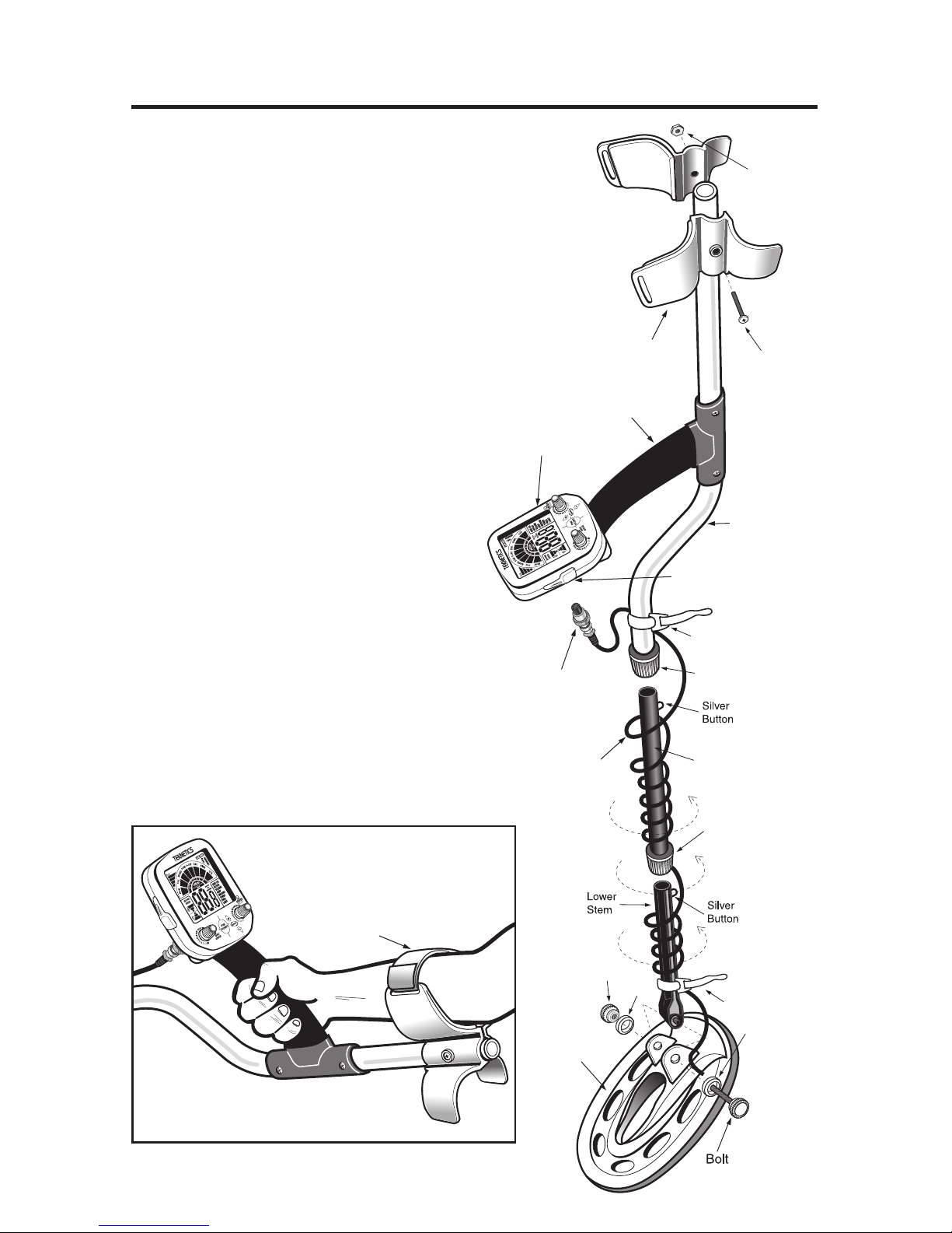
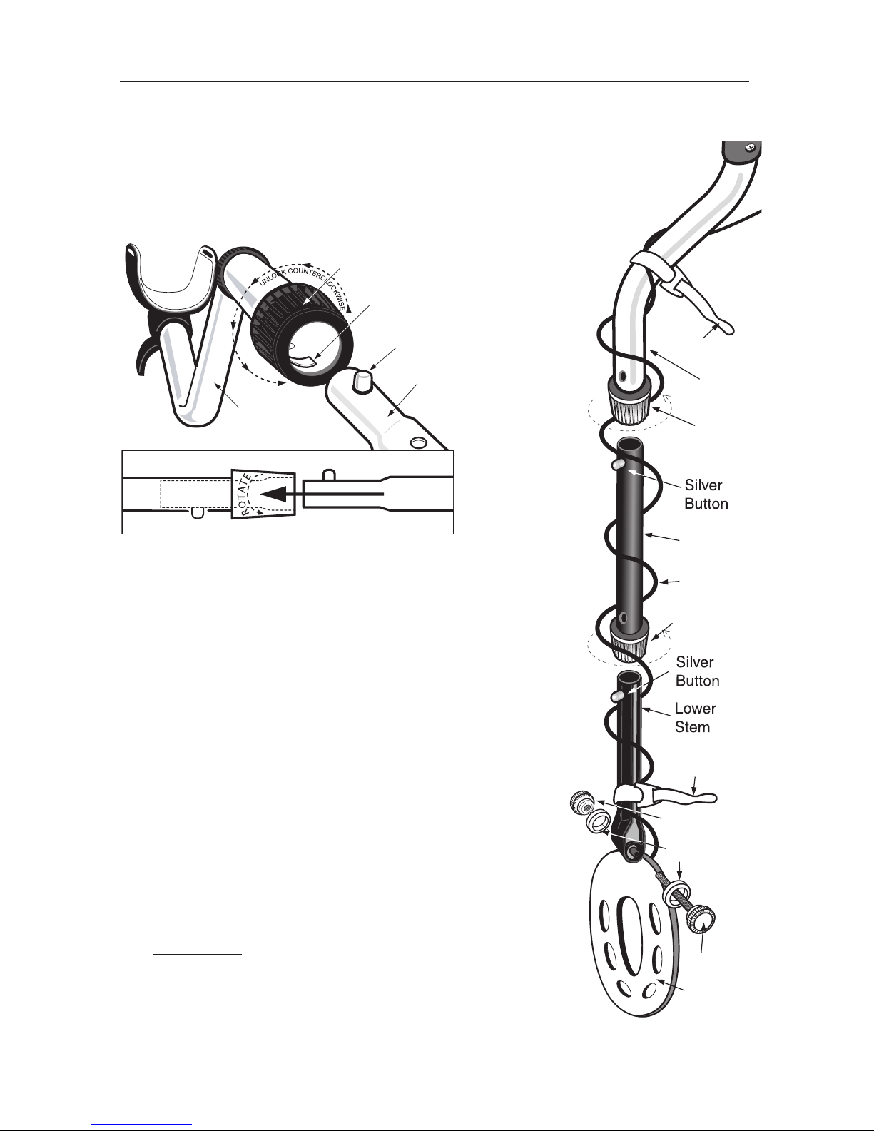
Assembly . . . . . . . . . . . . . . . . . . . . . . . . . . . . . . . . . . . . . . . . . . . .4-5
Batteries . . . . . . . . . . . . . . . . . . . . . . . . . . . . . . . . . . . . . . . . . . . . . . .6
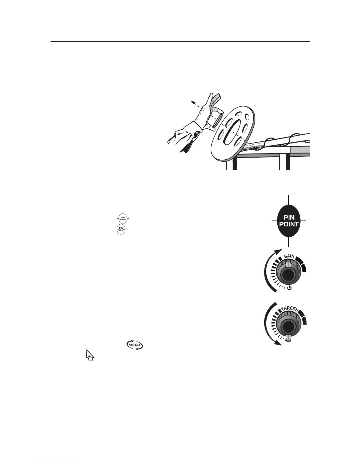
Quick-Start Demo . . . . . . . . . . . . . . . . . . . . . . . . . . . . . . . . . . . . . .7-8
Basics Of Metal Detecting . . . . . . . . . . . . . . . . . . . . . . . . .9-10
Ground Minerals . . . . . . . . . . . . . . . . . . . . . . . . . . . . . . . . . . . .9
Trash . . . . . . . . . . . . . . . . . . . . . . . . . . . . . . . . . . . . . . . . . . . .9
Identifying Buried Objects . . . . . . . . . . . . . . . . . . . . . . .9
Size and Depth of Buried Objects . . . . . . . . . . . . . . . . .9
EMI . . . . . . . . . . . . . . . . . . . . . . . . . . . . . . . . . . . . . . . .10
Headphones . . . . . . . . . . . . . . . . . . . . . . . . . . . . . . . . . . . . .10
Operation and Controls . . . . . . . . . . . . . . . . . . . . . . . . . . . . . . . .11-14
Display and Controls . . . . . . . . . . . . . . . . . . . . . . . . . . . . . . .11
Control Knobs . . . . . . . . . . . . . . . . . . . . . . . . . . . . . . .12
On/Off/Gain . . . . . . . . . . . . . . . . . . . . . . . . . . . . .12
Disc/AM/Thresh . . . . . . . . . . . . . . . . . . . . . . . . .12
Separate Gain and Threshold Controls . . . . . . .13
Touchpad Controls . . . . . . . . . . . . . . . . . . . . . . . . . . . .13
Ground Grab®Computerized Ground Balancing 13
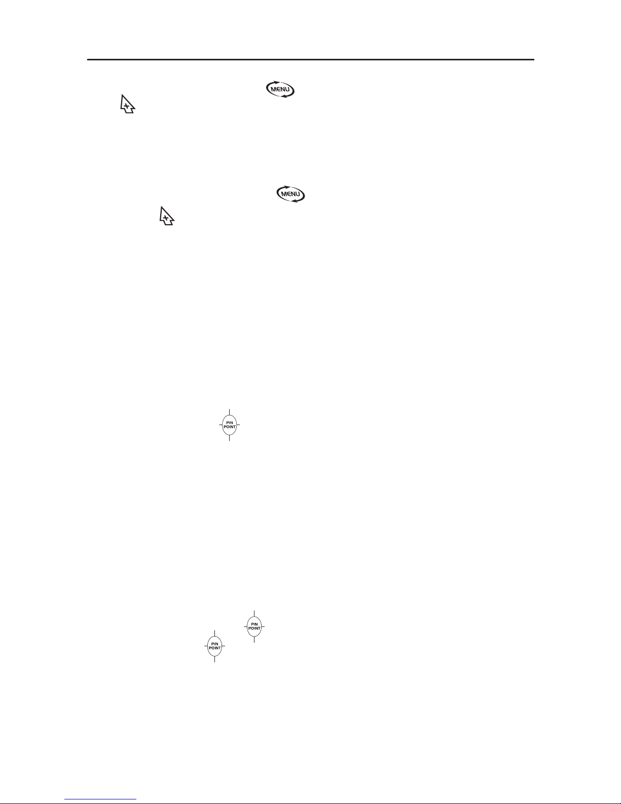
Pinpoint . . . . . . . . . . . . . . . . . . . . . . . . . . . . . . .13
Pinpoint Retuning . . . . . . . . . . . . . . . . . . . . . . . .14
Menu/Quick-Switch . . . . . . . . . . . . . . . . . . . . . . .14
Plus and Minus . . . . . . . . . . . . . . . . . . . . . . . . . .14
Menu Items . . . . . . . . . . . . . . . . . . . . . . . . . . . . . . .15-18
Discrimination Level . . . . . . . . . . . . . . . . . . . . . .15
Notch: Selective Target Inclusion or Exclusion . .15
Volume . . . . . . . . . . . . . . . . . . . . . . . . . . . . . . . .15
Notch Volume . . . . . . . . . . . . . . . . . . . . . . . . . . .16
Deep . . . . . . . . . . . . . . . . . . . . . . . . . . . . . . . . . .16
Ground . . . . . . . . . . . . . . . . . . . . . . . . . . . . . . . .16
Ground Grab Offset . . . . . . . . . . . . . . . . . . . . . .17
Tones: Variable Tone Selection . . . . . . . . . . . . . .17
d4 and d5 Tones . . . . . . . . . . . . . . . . . . . . . . . . .17
Frequency Shifting . . . . . . . . . . . . . . . . . . . . . . .18
Backlight . . . . . . . . . . . . . . . . . . . . . . . . . . . . . . .18
None Volatile Memory . . . . . . . . . . . . . . . . . . . . .18
Reset Factory (Factory Default) . . . . . . . . . . . .18
Ground Balancing . . . . . . . . . . . . . . . . . . . . . . . . . .19-20
Fe3O4Bar Graph . . . . . . . . . . . . . . . . . . . . . . . . . . . . .20
Ground Error . . . . . . . . . . . . . . . . . . . . . . . . . . . . . .20-21
Depth and Target Display . . . . . . . . . . . . . . . . . . . .22-24
Common Target Value Table . . . . . . . . . . . . . . . . . . . .24
Search Techniques . . . . . . . . . . . . . . . . . . . . . . . . . . .25
Target Pinpoint . . . . . . . . . . . . . . . . . . . . . . . . . . . . . . .26
Code of Ethics . . . . . . . . . . . . . . . . . . . . . . . . . . . . . . . . . . . . . . . . .27
Warranty . . . . . . . . . . . . . . . . . . . . . . . . . . . . . . . . . . . . . . . . . . . . . .27
Accessories . . . . . . . . . . . . . . . . . . . . . . . . . . . . . . . . . . . .Back Cover

TERMINOLOGY
The following terms are used throughout the manual, and are standard
terminology among detectorists.
ELIMINATION
Reference to a metal being "eliminated" means the detector will not emit
a tone, nor light up an indicator, when a specified object passes through
the coil’s detection field.
DISCRIMINATION
When the detector emits different tones for different types of metals, and
when the detector "eliminates" certain metals, we refer to this as the
detector "discriminating" among different types of metals.
Discrimination is an important feature of professional metal detectors.
Discrimination allows the user to ignore trash and otherwise undesirable
objects.
RELIC
A relic is an object of interest by reason of its age or its association with
the past. Many relics are made of iron, but can also be made of bronze
or precious metals.
IRON
Iron is a common, low-grade metal that is an undesirable target in certain
metal detecting applications. Examples of undesirable iron objects are
old cans, pipes, bolts, and nails.
Sometimes, the desired target is made of iron. Property markers, for
instance, contain iron. Valuable relics can also be composed of iron;
cannon balls, old armaments, and parts of old structures and vehicles
can also be composed of iron.
FERROUS
Metals which are made of, or contain, iron.
PINPOINTING
Pinpointing is the process of finding the exact location of a buried object.
Long-buried metals can appear exactly like the surrounding soil, and can
therefore be very hard to isolate from the soil.
PULL-TABS
Discarded pull-tabs from beverage containers are the most bothersome
trash items for treasure hunters. They come in many different shapes
and sizes. Pull-tabs can be eliminated from detection, but some other
valuable objects can have a magnetic signature similar to pull-tabs, and
will also be eliminated when discriminating out pull-tabs.
GROUND BALANCE
Ground Balancing is the ability of the detector to ignore, or "see through,"
the earth’s naturally occurring minerals, and only sound a tone when a
metal object is detected. This Detector incorporates proprietary circuitry
to eliminate false signals from severe ground conditions.
3

4
ASSEMBLY
Adjusting the Armrest
The armrest may be moved
forward or backward by removing
the single screw and nut and then
repositioning the 2-piece armrest.
Users with shorter arms may find
the armrest more comfortable in
the forward position. In order to
move the armrest backward, the
plastic plug must be removed from
the aluminum tube.
Armrest Strap
(Optional accessory)
The strap is available for purchase
as a separate accessory. Some
users prefer to use the strap when
swinging the detector vigorously, in
order to hold the detector secure
against the arm.
The detector can also be used
without the strap with no
compromise to detector balance
and stability under most conditions.
Battery
Compartment
(back side)
Handgrip
Nut
Screw
Searchcoil
Cable
Locking
Collar
Locking
Collar
Knurled
Knob
Middle
Stem
Cable
Plug
S-Rod
Armrest
Velcro
Strap
Velcro
Strap
Washer
Washer
Biaxial
Searchcoil
1/4” Headphone Jack
Optional
Armrest Strap

ASSEMBLY
(continued)
Locking
Collar
Locking
Collar
Middle
Stem
Cable
Knurled
Knob
Bolt
Searchcoil
S-Rod
Velcro
Strap
Velcro
Strap
Washer
5
●
1Position S-Rod upright.
●
2Rotate the LOCKING COLLAR fully in the
counterclockwise direction.
●
3Insert your finger inside the tube and make sure the
INTERNAL CAM LOCK is flush with the inside of the
tube.
●
4
Insert the MIDDLE STEM into the S-ROD,
with the SILVER BUTTON pointed upward.
●
5Rotate the MIDDLE STEM until the SILVER BUTTON
locates in the hole.
●
6Twist the LOCKING COLLAR fully in the clockwise
direction until it locks.
●
7Repeat this process on the LOWER STEM.
●
8Using the BOLT and KNURLED KNOB, attach the
SEARCHCOIL to the LOWER STEM.
●
9
Adjust the LOWER STEM to a length that lets you maintain
a comfortable upright posture, with your arm relaxed at your
side, and the SEARCHCOIL parallel to the ground in front
of you.
●
10
Wind the CABLE securely around the STEMS.
●
11
Connect CABLE PLUG to housing.
Do not twist the Cable or Plug. Turn Locking Ring only.
Use minimal finger pressure to start the threads. Do not
cross-thread. When the Locking Ring is fully engaged
over the threaded connector, give it a firm turn to make
sure it is very tight. When the Locking Ring is fully
engaged over the threaded connector, it may not cover all
of the threads.
●
12
Tighten both LOCKING COLLARS.
S-ROD
LOCKING
COLLAR
INTERNAL
CAM LOCK
SILVER BUTTON
MIDDLE
STEM
S-ROD MIDDLE STEM
●
2
●
3
●
4
●
4
●
5
*Note: Very tall users can purchase the optional Extended Lower Stem (TUBE5X), for extended reach.
Caution:
Forcing in MIDDLE STEM with CAM LOCK raised may form a burr on
cam lock. If this happens, remove burr with knife to allow insertion.

6
The detector requires a single 9-volt ALKALINE battery (battery not
included).
Do not use ordinary zinc carbon batteries.
Do not use “Heavy Duty” batteries.
Rechargeable batteries can also be used. If you wish to use rechargeable
batteries, we recommend using a Nickel Metal Hydride rechargeable battery.
The battery compartment is located on the back side of the housing.
Slide the battery door to the side and remove it to expose the battery
compartment.
BATTERY LIFE
Expect 20 to 25 hours of life from a 9-volt alkaline battery, longer if using
headphones. Rechargeable batteries provide about 8 hours of usage per
charge. Backlight use decreases battery life with significant drain at maximum
brightness.
SPEAKER VOLUME AND BATTERY CHARGE
You may notice the speaker volume drop while one battery segment is
illuminated. With one segment flashing, low speaker volume will be very
apparent.
BATTERY INDICATOR
The remaining battery life is proportional to the percentage of the battery icon
illuminated.
After the battery indicator begins flashing, expect the detector to shut off within
10 minutes.
BATTERY DISPOSAL & RECYCLING
Alkaline batteries may be disposed of in a normal waste receptacle or
recycled. Non-Alkaline batteries should be recycled. In the state of California
all battery types must be recycled. Please refer to local municipalities for
detailed disposal and recycling requirements.
BATTERIES

7
QUICK-START DEMONSTRATION
I. Supplies Needed
• Nail • Zinc Penny (dated after 1982)
• Nickel • Quarter
II. osition the Detector
a. Place the detector on a
table with the searchcoil
hanging over the edge.
Or better, have a friend
hold the detector, with the
searchcoil off the ground.
b. Keep the searchcoil away
from walls, floors, and
metal objects.
c. Remove watches, rings, and jewelry.
d. Turn off lights or appliances whose electromagnetic emissions may
cause interference.
e. Pivot the searchcoil back.
III. Press and hold then turn on detector with the GAIN
knob. Release . Set GAIN at the 12:00 position.
IV. Turn the THRESH knob all the way counterclockwise until
it clicks.
V. Wave each object over the searchcoil.
a. Notice a different tone for each object:
Bass Tone: Nail
Low Tone: Nickel and Zinc Penny
High Tone: Quarter
b. Motion is required.
Objects must be in motion over the
searchcoil to be detected in this mode.
VI. Press and release . DISC LVL will be activated.
Press until the word “IRON” disappears from the screen. Make sure
the word “FOIL” is still illuminated.
VII. Wave the nail over the searchcoil.
a. The nail will not be detected.
b. The nail has been “discriminated out.”
Q ick-Start Demo contin ed on next page

8
VIII. Firmly press and release once. DISC LVL will be activated. Press
until the words IRON, FOIL, NICKEL, P-TAB, S-CAP and ZINC all
disappear.
IX. Wave the Nickel over the searchcoil.
a. The nickel will not be detected.
X. Firmly press and release two times. NOTCH will be activated.
ress twice.
The word “NICKEL” will start flashing. Wait until the flashing stops.
“NICKEL” will be illuminated.
XI. Wave the Nickel over the Searchcoil.
a. The nickel is now again detected.
b. The nickel has been “notched in.”
XII. Rotating the THRESH knob clockwise places the detector in All Metal
Mode. Keep rotating the knob clockwise until you hear a faint hum. Pass
the quarter over the searchcoil. Vary the distance from the searchcoil on
each pass. Notice the changing pitch and volume.
XIII. ress-and-hold
a. Notice motion is not required. A motionless object induces a sound.
b. Notice the single audio tone. PINPOINT produces only this single
tone, regardless of the type of metal detected.
c. Vary the distance of the quarter to the searchcoil and notice the
changing depth-display values. The 2-digit reading indicates depth
distance in inches from the searchcoil.
XIV. Return To Factory Default
To reset the detector to the original factory default settings:
a. Turn off detector
b. Press and hold and then turn detector on.
c. Release
QUICK-START DEMONSTRATION
(continued)

9
THE BASICS OF METAL DETECTING
A hobby metal detector is intended for locating buried metal objects. When
searching for metals, underground or on the surface, you have the following
challenges and objectives:
1. Ignoring signals caused by ground minerals.
2. Ignoring signals caused by metal objects that you do not want to find,
like pull-tabs.
3. Identifying a buried metal object before you dig it up.
4. Estimating the size and depth of objects, to facilitate digging them up.
5. Eliminating the effects of electromagnetic interference from other
electronic devices.
Your metal detector is designed with these things in mind.
1. Ground Minerals
All soils contain minerals. Signals from ground minerals can interfere with the
signals from metal objects you want to find. All soils differ, and can differ
greatly, in the type and amount of ground minerals present. You therefore want
to “calibrate” the detector to the specific ground conditions where you are
detecting. This detector incorporates both automated and manual ground-
balancing features which will eliminate false signals from most types of soils.
If you want to maximize the detector’s target identification accuracy and depth
of detection, use the GROUND GRAB®. See the section on GROUND GRAB
®
Computerized Ground Balancing for details.
2. Trash
If searching for coins, which will induce higher tone sounds, you want to
ignore items like aluminum foil, nails, and pull-tabs. These undesirable
items induce lower tones. You can listen to the sounds of all objects
detected, and decide on what you want to dig up. Or you can eliminate
unwanted metals from detection by using the DISCRIMINATION features.
3. Identifying Buried Objects
When searching in the DISCRIMINATION Mode, different objects induce
different tones (high, medium, low, bass) and are classified on the display
screen in different categories. A 3-digit numerical reading is also provided in the
middle of the display for more precise target identification. The
DISCRIMINATION Mode requires motion: sweep the coil over the metal object.
4. Size and Depth of Buried Objects
When using the detector in the motion DISCRIMINATION Mode, the relative
depth of an object is displayed in the center of the display with the SIGNAL
strength indicator. A more accurate depth reading is available in a no-motion
search, using PINPOINT. PinPoint displays approximate target depth in
inches. This no-motion feature does not require the coil to be in motion to
detect metals. The ability to hold the searchcoil motionless over the target
also aids in tracing an outline of the buried object, or in pinpointing the exact
location of the object using techniques described in the pinpointing section.
Basics of Metal Detections contin ed on next page

10
THE BASICS OF METAL DETECTING (continued)
. EMI (Electromagnetic Interference)
The searchcoil produces a magnetic field and then detects changes in that
magnetic field caused by the presence of metal objects. This magnetic field
is susceptible to the electromagnetic energy produced by other electronic
devices. Power lines, microwave ovens, lighting fixtures, TVs, computers,
motors, etc., all produce EMI which can interfere with the detector and
cause it to beep when no metal is present, and sometimes to beep
erratically.
The GAIN control lets you reduce the strength of the magnetic field, and
thereby lessen susceptibility to EMI. You may want to operate at maximum
Gain, but the presence of EMI may make this impossible, so if you
experience erratic behavior or “false” signals, reduce the sensitivity, by
adjusting your GAIN and THRESHOLD controls.
HEADPHONE JACK
The detector has a 1/4” headphone jack on the left side of the housing.
When a headphone is connected, speaker audio is disabled. The
headphone jack has a rubber plug that will keep dirt and moisture from
entering the control box.
USING HEADPHONES
Using a detector with headphones facilitates
detection of the weakest signals and also extends
the battery life.
It also allows you to hear subtle changes in
the sound more clearly, particularly if
searching in a noisy location. For safety
reasons, do not use headphones near
traffic or where other dangers are
present. This device is to be used with
interconnecting cables/headphone
cables shorter than
three meters.
Headphone
Jack with
plug installed

11
OPERATION and CONTROLS
®
GND GRAB Press-and-hold key pad
to Ground Balance automatically.
PINPOINT Press-and-hold to pinpoint
target and view depth.
Alternate Function: Press once
while in VOLUME or GROUND
menu items, to enable
advanced options. PLUS and MINUS Press keypads once
to modify the active menu item.
Press-and-hold to repeatedly modify
the active menu item.
MENU/QUICKSWITCH Firmly press and
release to activate the menu and change
the menu item. Press-and-hold to
momentarily change modes.
ON/OFF/GAIN: Click right to turn ON.
Turn knob to increase GAIN. DISC/AM/THRESH Click left to enter
Disc mode; click right to enter
A/M mode. Turn knob to increase the
THRESHOLD setting.
Menu
Items
Number
Identifiers
Auto
Ground
Offset
Ground
Error
window
Backlight
Target
Categories
Overload
Indicator
Target
Category
Identifiers
Mineralization
Readout
Iron
Indicator
Signal Strength
Bargraph
Battery
Mode
Operation and Controls contin ed on next page

OPERATION and CONTROLS (continued)
CONTROL KNOBS:
1. ON/OFF/GAIN:
a. Click right to turn on. Click left to turn off.
b. Turning the knob clockwise increases the detector’s Gain; the higher
the Gain, the deeper targets will be detected, and the more likely the
detector will be able to detect very small targets.
c. As you turn the knob, notice the value at the center of the screen will
display your current Gain setting.
d. We suggest keeping the GAIN below 70 until you become familiar with
the detector’s operation.
e. At values greater than 70, some internal circuit noise will be noticed.
The higher the number, the higher this background “static” will be.
Many seasoned detectorists prefer to operate at high sensitivity level,
with the accompanying noise. They call this “working into the noise”.
When some background level of noise is audible, small changes in the
volume and tone will denote the presence of buried metal.
2. DISC/AM/THRESH
a. Click clockwise to enter the All Metal Mode.
b. This is the detector’s most sensitive mode of operation.
c. It is a motion mode of operation; the coil must be in motion to detect metal.
d. All Metal Mode induces a hum whose pitch and volume vary with the
size of the target. Larger targets and targets moving closer to the
searchcoil will increase the tone’s pitch and its volume.
e. As you turn the knob, the THRESH value will be display at the center
of the screen.
f. Turning the knob clockwise increases the threshold, and allows more
signal into the machine. At about zero threshold the noise floor should
start becoming audible.
g. See the section “Deep and Threshold settings interaction” (page 15).
Operation and Controls contin ed on next page
DISC LVL
NOTCH
VOLUME
DEEP
GROUND
TONES
FREQFREQ
LIGHTLIGHT
12

13
OPERATION and CONTROLS (continued)
Separate Gain and Threshold controls
The gain setting factors the amplitude of the signal coming from the coil. The
threshold setting sets the minimum signal strength required to get a
response, and audibly, the “hum” level in All Metal Mode. Together, these two
settings control the overall sensitivity of the machine.
TOUCHPAD CONTROLS:
GND GRAB: Ground Grab®Computerized Ground Balancing.
This allows you to set the detector’s internal ground setting equal to the phase
of the ground you are searching.
See the section on Ground Balancing (page 19), for a more throughout
explanation of this feature.
Press-and-hold to invoke automatic ground balancing. This will “grab”
the ground value.
In order to determine the most accurate ground value, pump the coil up and down
over the ground while standing in one place over a patch of ground-free of metal.
1. Locate a patch of metal free soil.
2. Start with the searchcoil about 6” above the ground. Press and hold ,
lower and raise the coil to within an inch of the ground in a pumping motion.
3. Continue this pumping motion and watch the Ground Phase number in the
center of the display.
4. Once this number remains constant, the detector has correctly measured
the Ground Phase.
5. Release the . This will internally set the Ground Phase to the value
displayed.
To manually adjust the ground setting, see the “GROUND” menu item on page
16. If while performing Ground Grab, one of the arrows in the GROUND
ERROR window is flashing, see the “Ground Grab Offset” section on page 17.
PINPOINT
Press and hold to activate. Searchcoil motion is not required; a motionless
searchcoil over a metal target will induce sound. Audio is VCO The 2 digit
number displayed indicates target depth, in inches. The scale is calibrated to
coin-sized objects.
After you have identified a target using a motion mode of detection, press and
hold to identify the target’s exact location. This technique can yield more
information about the target’s shape and size and also find its exact location to
facilitate extraction.
PINPOINT AS FOLLOWS
:
1. Position the searchcoil just barely off the ground, and to the side of the target.
2. Press and hold
3. Move the searchcoil slowly across the target and locate it by sound.
The target is located directly below where the sound is the loudest.

14
PINPOINT RETUNING
Retuning in Pinpoint Mode is useful in narrowing down the location of a target.
To retune the detector, release the button and immediately depress it again.
1. To Narrow the response further, position the center of the searchcoil slightly
off the center of the target, while still depressing
2. Release .
3. Immediately press-and-hold again.
4. Repeat this procedure to narrow the field of detection further.
Note: Depth indication is less accurate after narrowing.
MENU/QUICK-SWITCH
This double function touchpad is used to activate and navigate the menu and to
momentarily change modes. To operate the Menu, firmly press and release the
touchpad. Note that the Menu actuates on the release of the touchpad. Press
and Hold to momentarily switch modes.
MENU. The menu system packs the feature set in a dynamic and intuitive
fashion. It also has extended hidden features for the advanced user.
Access: Press and release , to enable menu items.
QUICK SWITCH. Quick Switch alternates between ALL METAL and
DISCRIMINATION Modes. It is useful when trying to listen a deeper target, or
when trying to pinpoint the target without using the static signal.
Access: Press and hold to alternate between DISCRIMINATION and ALL
METAL Modes
PLUS and MINUS
Use and to modify and adjust the active menu item. Press and release once
to modify menu items, or press and hold for continuous adjustment.
OPERATION and CONTROLS (continued)

15
MENU ITEMS
DISC LVL: Discrimination Level
Discrimination allows you to eliminate metal objects from detection. It is
adjustable from 0 to 80. A discrimination setting of zero is not the same as All
Metal. Discrimination incurs some loss of sensitivity to small and deep objects.
As you adjust the discrimination level, a number will appear in the center of the
LCD. All targets that report a number LOWER than the set discrimination level
will not report a sound or display activity. They have been eliminated from
detection. Note also that target category identifiers will start disappearing from
the top of the LCD screen as you increase the discrimination level. When a
target icon disappears, it means the whole category has been eliminated from
detection. Lowering the DISC LVL setting will make the target category
identifiers return to the screen, even if they are partially eliminated by the
numerical setting.
Access: Press and release the MENU/Quick-Switch button until DISC LVL menu
item becomes active. Then use and to adjust the discrimination level.
NOTCH: Selective Target Inclusion or Exclusion
a. The purpose of the NOTCH function is to change the detection status of
a target category and it functions only in DISCRIMINATION Mode.
• If a category was not eliminated from detection, then notching that category
will eliminate it from detection and the category icon will disappear.
• If a category was eliminated from detection (category’s icon not
illuminated), then notching the category will return the category to an
active state and the icon will reappear.
b. The following target categories can be notched in or out:
Foil, Nickel, P-Tab, S-Cap, Zinc, Dime, Qtr. After the Qtr category,
pressing NOTCH will exit the NOTCH function.
c. To select a category for notching, press NOTCH until the desired category
identifier flashes. After a few seconds, the flashing will time out and the
current target category will be notched.
d. Practice pressing NOTCH a few times and its function will become obvious.
The NOTCH feature is not available in ALL METAL Mode.
Access: Press and release until NOTCH menu item becomes active.
Then use and to select desired target category. Repeat the operation to
notch additional categories.
VOLUME
The audio response is limited by the volume setting and it applies to all of the
detector settings in all modes including user interface sounds and alarms. In
addition to target volume it affects PINPOINT, Overload alarm, Ground Grab
over metal alarm and all keypad button “beeps”. It does NOT affect the
sensitivity of the detector. The adjustable range is from 0 to 10.
Access: Press and release until VOLUME menu item is activated. Use
and to modify the audio volume.
Vol me contin ed on next pag

16
NOTCH VOLUME – Adjustable Volume Offset by Target Category
Each target category can have its volume adjusted independently. This
advanced setting affects the Master Volume setting and functions only in
DISCRIMINATION Mode.
Access: In Disc Mode, press and release until VOLUME menu is activated.
Press repeatedly to cycle through the various target categories. NOTCH
VOLUME will be displayed on the LCD and each category will blink when it is the
active. Select desired category and use the and to set a negative notch
volume offset. This offset will apply to the Master Volume setting. For example,
if the master volume is set at 10, and your Notch Volume offset is -3, the volume
for that target category will be at “7”. If you set an offset of -5, the volume would
be “5”. Notch Volume range is from 0 to -9. Changing the master volume will
change Notch Volume offsets accordingly. Make note when you set Notch
Volume offsets because there is no indication on the screen when they are active.
DEEP
This allows 4 settings with varying filters that may increase depth under certain
conditions.
D0.Fast filter. Best for target separation and searching in heavy trash. It is
the least sensitive of the Deep settings.
D1.Regular filter. Best for general conditions.
D2.Deep filter plus 60 Hz notch. This is a slower return setting that will
eliminate some EMI. The noise floor will be increased. This mode is best
used in cleaner soils and Sensitivity must be adjusted for proper use.
D3.Deep filter plus 50 Hz notch. Same as D2, but with a 50 Hz noise filter.
Access: Press and release the until DEEP menu is activated. Use and
to select desired mode.
Deep and Threshold relationship. The DEEP Mode settings can affect the
gain of the detector, most notable in the All Metal Mode. You may have to adjust
the threshold. If Threshold knob seems ineffective, momentarily press to
reset internal offsets.
GROUND
This menu item allows you to manually change the ground balance setting. It
is active only when in the All Metal Mode. By contrast, the Ground Grab
feature automatically matches the detectors ground balance with the actual
ground phase; with GROUND you can manually adjust it up or down. This can
be beneficial, depending on the conditions you encounter. For example, if you
are in very clean soil with no mineralization, you could adjust the GROUND
setting up several digits. This would allow a slight increase the capability of the
detector. Or if you are in highly mineralized soil and hearing a lot of “chatter”
you could manually adjust the setting down several digits. This would quiet the
detector down and allow you hear desirable targets easier.
Access: In All Metal Mode, press and release until GROUND menu item
becomes active. Then use and to modify the detectors ground setting.
Adjust the setting while pumping the coil up and down. Some users prefer to
manually adjust ground after a GROUND GRAB operation, to fine tune it. See
the GROUND BALANCING section for more information.
Men Items contin ed on next page
MENU ITEMS (continued)

17
MENU ITEMS (continued)
GROUND GRAB OFFSET
This advanced feature is only available while in the All Metal Mode. You can
program an automatic Ground Grab offset, positive or negative. When an
offset is programmed, you will see a visible indicator on the LCD each time you
perform a Ground Grab. A “plus” or “minus” blinking arrow will displayed in the
Ground Error section. ( )
Access: In All Metal Mode, press and release until GROUND menu item
becomes active. Then press . Use and to set a Ground Grab offset
value. This number will be added or subtracted from the Ground Grab setting,
depending on your entry.
TONES: Variable Tone Selections
In Discrimination Mode, the Omega 8500 has 5 different pre-set tone variations
to choose from. See the table below detailing the settings of the 5 options.
Select the option that best suits your needs or conditions.
d4 and d5 Tone Options
These two settings give the most varied audio tones and are identical except for
one thing. The d5 Tone eliminates proportional audio and gives full audio
response to even the smallest signals. This option is often preferred when
searching for deep targets, enhancing the audio and making them very easy to
hear. The d5 tone option also affects the Multiple Target Category System (see
Target-ID Indicators, page 23.) Normally, the primary Target-ID indicator Icon is
black and the secondary target indicators will be grayed-out or half-tone. In d5
tone setting, both primary and secondary Target-ID indicators will be solid black.
This will help when light conditions make it difficult to see the half-tone indicators.
Access: In Disc Mode, press and release until TONES menu become
enabled. Then use and to select desired tone option.
In All Metal Mode, the TONES feature allows the user to vary the pitch of the
VCO tone by selecting one of four frequencies.
Variable VCO Tone. The audio pitch of the VCO base tone can be varied by
selecting one of four pre-set frequencies. This allows users to select the base
tone they are comfortable with.
Access: In All Metal Mode, use the Threshold knob to set a slightly audible
threshold sound. Press and release until TONES menu item is activated.
Use the to select one of the 4 tone options, A1 through A4. Note
the change in audio pitch. This setting will carry over to all functions and
modes using the VCO tone.
d5 Tone contin ed on next page
Setting
Iron Foil NickelPulltabS-CapZinc Dime Qtr
5
Bass Low Medium Low Low Low High High
4
Bass Low Medium Low Low Low High High
3
Bass Low Low Low Low Low High High
2
Bass Low Low Low Low Low Low Low
1
VCO VCO VCO VCO VCO VCO VCO VCO
Proportional
audio
No Proportional
audio
Proportional
audio
Proportional
audio
Proportional
audio

18
FREQ: Frequency Shifting
If the detector chatters or is noisy while the coil is motionless, the cause is
either internal circuit noise due to too high sensitivity setting or from
electromechanical interference (EMI). If reducing the gain does not improve
the operation, try switching between the alternate frequency settings. You may
find a frequency option that eliminates the noise. Shifting the frequency may
have an effect on the ground balance so as a precaution; we recommend you
re-ground balance after changing the frequency.
Changing frequency may require you to change the ground balance setting.
See section on ground balancing.
LIGHT: Adjustable Backlight
The Omega 8500 has an adjustable backlight option, with adjustments levels
from 0 to 5 in increasing levels of intensity. Use of the backlight feature will
drain the battery power at a faster rate.
Access: Press and release until LIGHT menu item is activated. Use the
to select desired backlight setting. Use the “0” setting to turn backlight off.
NONVOLATILE MEMORY
The Omega 8500 will save in memory your settings when the detector is turned
off, with the exception of the backlight and ground balance. Backlight default is
OFF and Ground Balance is 82.9.
Access: Automatic when powering detector off.
RESET Function
This operation restores all the original factory default settings.
Access: Turn detector off. Press and hold and turn detector on. The
number displayed on the LCD is the software version. Release the and
the detector has been reset to default settings below.
MENU ITEMS (continued)
Setting Factory Default
DISC LVL 0
NOTCH NONE
VOLUME 7
NOTCH VOLUME IRON 0
NOTCH VOLUME FOIL 0
NOTCH VOLUME NICKEL 0
NOTCH VOLUME P-TAB 0
NOTCH VOLUME S-CAP 0
NOTCH VOLUME ZINC 0
Setting Factory Default
NOTCH VOLUME DIME 0
NOTCH VOLUME QTR 0
DEEP 1
GROUND 82.9
GROUND OFFSET 0
TONES DISC d3
TONES A/M A1
FREQ 0
LIGHT 0

19
GROUND BALANCING
WHAT IS GROUND BALANCING?
Why do I need to Ground Balance?
All soils contain minerals. Signals from ground minerals are often tens
or hundreds of times as strong as the signal from a buried metal
object. The magnetism of iron minerals, found in nearly all soils,
causes one type of interfering signal. Dissolved mineral salts, found
in some soils, are electrically conductive, causing another
type of interfering signal.
Ground Balancing is the process by which the metal detector
cancels the unwanted signals coming from the ground
minerals while still detecting the signals from buried metal
objects. This is accomplished by matching the detector’s
ground balance setting to the phase of the ground signal.
When the detector is calibrated to the soil, the result will be deeper target
detection, quieter operation, and more accurate target identification.
How to Ground Balance your Detector:
1. Turn the detector on and set GAIN at the 12 o-clock position.
2. Click the right knob to All Metal Mode.
3. Adjust the THRESHOLD control knob to the point where you can hear
a slight background hum.
4. Sweep searchcoil across the ground to find a clear patch of ground
with no metal present.
5. Press and hold touch pad, and pump searchcoil repeatedly over
the clean ground, keeping it level with the ground. Start about 6”
above the ground and lower to within 1” of the ground. See illustration
above.
6. When the ground phase value number displayed in the screen center
settles down to an unchanging number, the detector has been ground
balance. Release touch pad.
If during this process you see a blinking arrow in the Ground Error window that
indicates an automatic GROUND GRAB OFFSET has been programmed.
Understanding ground conditions assists the user in setting up the detector,
knowing when to readjust ground balance, and in understanding the
responses of the detector while searching.
This detector provides two kinds of ground data:
1. The type of mineralization (which affects where the ground phase should
be set.) This is GND HASE.
2. The amount of mineralization (the greater the amount of mineralization,
the greater the loss of detection depth & ID accuracy; the loss is more
pronounced in Discrimination Mode. This is the Fe3O4.
Gro nd Balancing contin ed on next page
Pumping coil
to ground
balance with
Ground Grab
button.

20
GROUND BALANCING -Technical In o
Fe3O4BAR GRA H
The Fe3O44-segment bar graph indicates the amount of ground mineralization,
independent of type, expressed as an equivalent volume concentration of
magnetite (Fe3O4). It updates every second. It is sensitive to motion and will give
the most accurate readings if you “pump” the searchcoil up and down several times
over the ground. The presence of metal or “hot rocks” will cause the readings to be
inaccurate. If you stop moving the searchcoil, the bar graph will go blank.
INDICATION % Fe3O4 SUSCE TIBILITY
4 Bars -High 0.4 - 1.6 1,000 - 4,000
3 Bars -Medium 0.1 - 0.4 250 - 1,000
2 Bars -Low 0.025 - 0.1 60 - 250
1 Bars -Very Low 0.006 - .025 15 - 60
None - - less than .006 less than 15
Magnetic susceptibility is expressed in micro-cgs units. In a salt water
environment in the absence of iron minerals, the bar graph indicates relative
electrical conductivity.
In soils with greater than 4,000 micro-cgs units magnetic susceptibility, the
signal from the soil may saturate (“overload”) the circuits. This will not harm the
detector but the machine will not be usable in that condition. The solution is to
hold the searchcoil several inches above the soil surface so it isn’t “seeing as
much dirt”. By listening and watching you will know how high you need to hold
the searchcoil in order to avoid overload.
The highest magnetic susceptibilities are usually found in soils developed over
igneous rocks, in alluvial ‘black sand” streaks on beaches, and in red clay soils
of humid climates.
The lowest magnetic susceptibilities are usually found in white beach sands of
tropical and subtropical regions, and soils developed over limestone.
Ground Error
The bottom left-hand corner of the display contains a graphic which indicates
if your detector’s ground balance setting needs to be adjusted.
The Omega has a tracking system which continually analyzes the phase of the
ground you are scanning. It then compares this ground phase value with the in-
ternal Ground Setting established at the time the detector was ground balanced
using GND GRAB or the manual ground balance method.
* If the detector’s internal Ground Setting is equal to the actual phase of
the ground, the detector is properly ground balanced and the Ground
Error window is clear.
* When the detector’s internal Ground Setting is higher than the actual
phase of the ground, the bars on the top of the graph will be illuminated.
The bigger the error is, the more bars will show up.
Gro nd Error contin ed on next page
Table of contents
Other Omega Metal Detector manuals
Popular Metal Detector manuals by other brands

Harbor Freight Tools
Harbor Freight Tools 43149 Set up and operating instructions

GOLDEN MASK
GOLDEN MASK DEEP HUNTER Pro3 instruction manual

Sears
Sears 321.596390 owner's manual

Minelab
Minelab Golden Hawk user manual

Bounty Hunter
Bounty Hunter titanium Camo owner's manual

Bounty Hunter
Bounty Hunter Land Ranger PRO owner's manual

Eriez
Eriez 1250 ANALOG Installation, operation and maintenance instructions

Whites
Whites Coinmaster 400 Series 2 Operator instructions

Whites
Whites Conquistador 200 Operator instructions

Centech
Centech 94138 Assembly and operating instructions

Whites
Whites Coinmaster 1/DB Series 2 Operator instructions

JW Fishers
JW Fishers PULSE 8X Operation manual