Mikron NRG 150 Operation instructions

1
NRG 150
User’s operating manual
Made in Bulgaria

2
In order to use the device for a maximum long time and without problems, as well as to
be able to use all of its options, please read carefully the whole instruction manual and
observe the directions in it.
Your NRG 150 is shipped with these parts:
- Upper Pole Assembly –fully assembled, including upper pole stem with
handle grip
- Middle pole assembly with pole lock
- lower pole - made of plastic in order to not disturb the work of the coil.
- 27 cm DD search coil
- electrical set box –made of extremely strong plastic, including 8 AA alkaline
batteries or 10 rechargeable accumulators NiMH 1,2V/2800mAh.
- 220V automatic charger
- Operation user’s manual
Warranty card
If any of these items are missing, immediately inform us or our authorized
dealer where you purchased your detector.
Assembling the NRG150 is simple and you don’t need any special tools.
Just mount the search coil on the lower pole assembly, connect the pole
assemblies together, adjust the pole length, wrap the excess cable around the
pole and plug the cable into the control unit. Finally adjust search coil angle to
your preference and you are ready.
NOTE: Do not allow the cable to flop loosely over the search coil. Since the
detector is sensitive enough to „see“ the tiny wires in the cable, a floppy cable
can cause false signals as the search coil senses the moving wires.

3
CONTROLS:
NRG 150
control panel:
- “GROUND BALANCE” –eliminates the signals of the ground mineralization.
- “DISC” –regulates degree of elimination of iron and unwanted objects.
- “THRESHOLD” –used for adjusting sound level and regulates depth of.
- “ON / VOLUME” –switches on the detector and adjust sound level
- “SAT SPEED” - (Self Adjustment Threshold) SAT Speed –adjustable rate
beep on detection of metal objects.
- Button “Auto GEB” –turns on and off automatic ground balance.
- Button “LIGHT”–switch on and switch off LCD backlit.
- Jack “Phones” –used for head phones (one 3,5mm on the front panel, and one
6,3mm. on the bottom side of the box)
1. Assembling of the device:
The bearing rod is assembled by inserting of the lower part into the upper
one. Choose the desired length of the whole construction and the fixing clamp
is tightened between both parts of the bearing rod. The lower part of the
bearing rod is put with the opening between the ears of the coil and the plastic
bolt is tightened by choosing the position of the coil to be parallel to the
ground surface. The coil cable must be wind up tightly around the bearing rod
and is switched to the socket of the box with electronic. Upon switching of the

4
cable of the coil to the socket on the box, tighten the well the metal nut of the
coupling to the terminal of the box. Upon switching off, unscrew the nut
completely and pull out the coupling without pulling or twisting the cable of
the coil. This way, you will prevent the cable and the conductors in it from
breakdown or short circuit.
The searching coil is approached to the surface of earth by paying attention to
avoid presence of metals within its range.
NOTE: Detector may not work as expected indoors due to the high degree of
metals used in modern construction. It is best to tune and practice outdoors to
ensure stable, predictable results.
2. Switch on and work with NRG 150.
1. Turn the “ON / VOLUME” knob to “ ON” and adjust preference volume of
sound. The display will momentarily show an opening screen which lists the
software version.
2. Setting the “THRESHOLD” - While holding the detector a few feet above
ground and away from any metal object, slowly turn the “THRESHOLD”knob
until you hear a very slight audio tone through the speaker or headphones. This
is the optimum set-point for the “THRESHOLD”. If the search coil is not in
motion and not close to metal, the detector should be silent. A light “buzz”
adjustment is recommended to insure optimum depth and maximum
performance.
As “THRESHOLD” is in low position, as low is sensitivit y. Too low of a
threshold setting may cause very weak signals to not be heard. Too high of a
threshold setting may cause operating instability.
3. You can work in manual or in automatic “GROUND BALANCE”modes:
- In manual ground balance mode:
Search for and select a clear piece of ground or sand that does not contain any
metallic targets. With the coil elevated at least waist high and away from any
metallic target, slowly adjust the THRESHOLD control until a very faint audio
threshold signal is heard.

5
Lower the search coil to within one-inch of the ground surface while listening
to the threshold audio signal. If the threshold signal is high tone, the
“GROUND BALANCE” control needs to be decreased (rotate counter
clockwise). If the threshold signal is low tone, the “GROUND BALANCE”
control needs to be increased (rotate clockwise). Keep repeating this step until
threshold signal is the same within one-inch of the ground as it is in the air.
Once this is accomplished, the detector is properly ground balanced.
When the ground mineralization is rejected, the detector can see deeper targets,
and is less susceptible to ground interference.
While balancing the detector, you have to be sure there are no metal objects
around the search coil. If it seems difficult or impossible to get little change in
the steady threshold as the coil is lowered, you may be attempting to tone on
top of a peace of metal. Move to a different spot on the ground and repeat
balancing. Once the initial ground balance is completed, the detector is ready to
be used.
2 - 20cm.
Fig. 1
A proper adju stme nt of the manual ground balance will enable a little more
depth over automatic ground balance. However, an improper adjustment of the
manual ground balance could and in all probability decr ease the depth
performan ce of the metal detector greatly.
-In automatic ground balance mode: push the button “Auto GEB”and
you will hear a beep.
The ,,GROUND BALANCE” knob do not have to be turned on at that time!! If
you sweep the search coil over non-ferrous metals (gold, silver, copper, bronze)
a high-toned sound can be heard; and if you sweep over ferrous metals a low
sound is heard. Without the ability to cancel ground mineralization, a metal
detector could respond to mineralization as if it where a good target.

6
Always try to manual balance to the ground surface, and if it seem difficult or
impossible to get little change in a steady threshold as coil is lowered, we
recommend use “Auto GEB” reg ime. Use “Auto GEB” when you find yourself
in a situation that does not allow manual ,,GROUND BALANCE” to be
adjusted correctly.
The ground conditions are really bad with mineralized ground, hot rocks and
iron trash, so your sweep speed must be reduced for best results.
“Auto GEB” is recommended when searching in wet salt sand too.
NOTE: Under some severe mineral conditions ground balancing may not be
possible. The best result you will get if searching when the soil is dry.
Fig.2
NRG 150 working in dynamic regime - searching metal objects is made by
moving search coil toward ground surface –fig.2 , fig.3
Wrong Correct
Fig.3
Start swinging the search coil in wide sweeps that overlap each other, as near to
the ground surface as possible-Fig.2 The search coil should not touch the
ground during your sweep. The pole length should be adjusted to allow this
without having to lift the detector with your elbow or shoulder. The search coil
should rest about one inch above the ground while you are standing erect. The
angle of the search coil should allow the bottom to be parallel to the ground.

7
If you experience false signals or constant beeping or popping and you are not
near common sources of electrical interference, push "Auto GEB" to switch on
automatic balancing and/or reduce Threshold (counterclockwise) slightly and
try again.
As a search coil is swept over the ground, ignore the display and concentrate on
the sound the detector makes. As a search coil is passed over a metal that is
likely iron trash, the sound will be low tone (245Hz). Once familiar with the
sound typical iron produce, an operator may pass over such targets without
consulting the display indication, and continue searching, saving more time.
As a search coil is passed over a metal that is likely good, high tone sound will
be heard (700Hz). A good target typically produce a longer, more solid sound,
no partial signals and mixed signals: high-low tone. Once a smooth solid signal
is heard, sweep the search coil over the target several times and look at the
display indication.
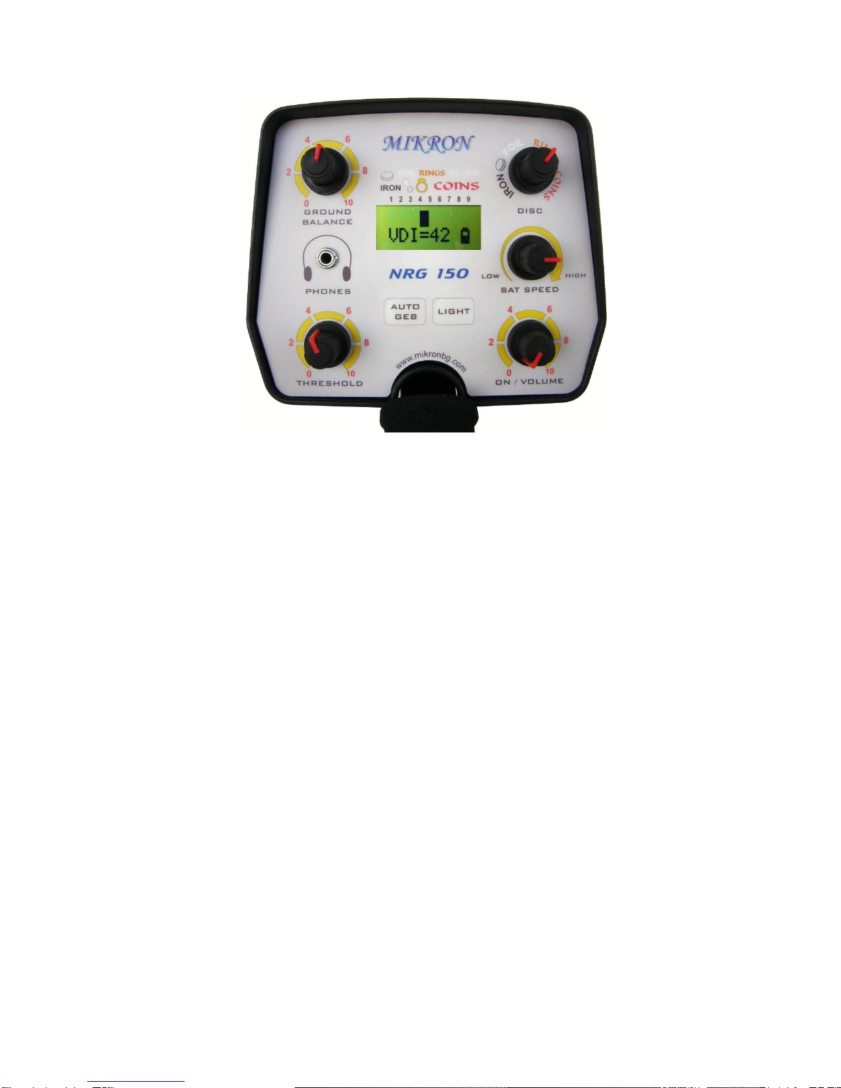
When a metal target is detected,probable target type will be indicated at
the top of the LCD screen. The Upper Scale, where the VDI cursor is
illuminated when hunting, consists of eight (8) graphical segments for more
precise Target ID and discrimination.
-First segment indicates the metal is likely iron or steel, such a nails, steel
bottle cap, or iron relic. At the same time, the sound is low tone (if not switch
on IRON MASK mode). Dig if only iron/steel is of interest.
-Second segment indicates of small foils. However, some very small gold
jewelry can also be indicated by this segment. You may want to dig this target
in areas where small gold jewelries are suspected.
-Third segment indicates small gold coins, rings, medium jewelry, and
small ancient coins. The most desired metal - gold, usually displayed in this
segment. However, large and solid foils can be indicated by this segment too.
-Fourth segment indicates most likely old bronze coins, medium to larger
gold jewelry or gold coins. However, aluminum pull tab can also be indicated
by this segment.

8
-Fifth segment indicates medium copper or zinc coin, or large aluminum
screw caps. Sometimes, a large gold rings or coins can be indicated by this
segment.
-Sixth and seventh segment most often indicates small silver coins, also
big bronze or copper coins.
-Eight segment almost always indicates high purity silver, big silver coins,
but sometimes, old big bronze coins and other items of bronze without impurity.
Each of the 8 segments operates independently. It can't be displayed
simultaneously two or more segments.
Often when detecting very old rusty iron objects and some iron with
impurities of nonferrous metal such as galvanized steel, or iron bottle caps,
indication on the 1-st row jumps from the first to the last segment, and vice
versa. This is always a signal that is detected magnetic object. Such items of
dubious and mixed signals more accurately identified as iron, if you detect with
the edge of a search coil than if you are just below the center of the coil.
Highly mineralized soils have a greater impact on the detector and thus the
accuracy of VDI. In high mineralization detected signals can be changed with
graphical and digital indication, than when tested in air or in low mineralized
or sandy soil. Usually such places VDI is shifted to the left. For example, if one
normal metal object is detected with the "sign" of the fourth or fifth segment, if
buried in such mineralized ground, indication may be the second or third
segment. So whenever in doubt of the display, check the detected object, and so
over time you will learn to some extent to recognize what has detected metal
detector!
When a metal target is detected, аlong with the VDI cursor of the first row,
you can see their common VDI numbers (0-99), on the bottom row on the
screen.“VDI = “.
VDI (Visual Discrimination Indication) is a digital indication which
depends on the metal targets exact alloy, size, and shape. The reference label
below the display provides a comparison of known targets and their common
VDI numbers. Different metal targets may share the same VDI numbers based

9
on their electrical characteristics. VDI numbers from 0 to 99 are available and
cover the entire range of alloys and sizes.
Whenever detection of metal objects, initially concentrate on the sound
signal, so you can better determine the exact location of the object.
3. “DISC” knob is used to eliminate any target that you do not want the
detector to audibly respond to.
If you need to eliminate more ferrous metals over the ground, the “DISC”
control must be set in a position over “ Rings” or “Coins”. If you come upon
non-ferrous metals /gold, silver, copper, bronze/ a high sound can be heard; and
if you come upon ferrous metal a low sound is heard. If the “DISC” control is
in low position - “Iron”, every ferrous object will be signalized with high tone
(like non –ferrous). If the soil is too mineralized we recommend the “ Foil” or
“Iron”position.
Some trash metals such as pieces of lead, tin, cannikin or pot metal will
produce a good sound regardless of the DISC position.
4. IRON MASK modе.
With the trigger on the hand grip in the forward position, you can switch on
IRON MASK mode. Indication that you will see the display - the first segment
will be blacked out with the symbol IRON MASK.
When you switch on this mode, will be disabled low tone on detection of a
magnetic metal. This mode is preferable when working in areas heavily
contaminated with iron trash.
IRON MASK symbol VDI cursor

10
Note: If the potentiometer "DISC" is reduced to a minimum, the detector will
detect ferrous (magnetic) objects with high tones, but will not display an
indication of the type of metal, as it would be the first segment, and in this
mode it is indicated by a symbol for IRON MASK. Therefore it is preferable
when use mode IRON MASK, potentiometer "DISC" to be increased to at least
position FOIL or more.
When switch off mode IRON MASK, i.e. return the trigger in the middle
position, the detector will work again in the Two Tone mode - high tone for
non-ferrous metals and low tone for ferrous metals. At the same time, will
disappear and the symbol for IRON MASK on the first line of the display.
5. Searching:
NRG-150 can work with 2 search coils - 27 cm. and 36 cm. Large 36cm. search
coils are used to detect large and bulky metal objects deeply buried to about 1.2
to 1.5 m maximum, and a small probe is used to detect and precisely locate
single coin depth of about 30-40cm. or a large metal objects at depths up to 1 to
1.20 m (depending on size). Also, smaller coils can be used in bushes, bumpy
and uncomfortable search location where it is impossible to use large coils.
The greater the size of the search coil, the greater will be the depth of
detection, but with the increase of the coil size, will be hard to detect very
small metal objects. The difference in depth of detection using large coils is
appreciable for large metal objects such as a large metal object is, the greater
the difference in depth of detection between large and small search coils! I.e. if
the difference in depth of detection of large and small coils for medium coin is
3-4cm., the difference in depth of detection as metal cup or pot of coins is
about 15 cm. Therefore, the use of large coils makes sense if you look bulky
items and it is important to find the best possible depth. Disadvantage of larger
sensors is their size, require a flat and clean places to look. In contaminated
areas with lots of scrap metal is advisable to use smaller probes.
To test for studying the characteristics of the device, you can make polygon
where buried various metal objects at different depths. Also you can put to the

11
ground sizes metal objects. Move the search coil at different heights above
them and you will learn to evaluate the size and depth of the metal object
depending on the intensity and duration of the sound. After a while you will
learn to recognize objects that lie just below the surface or at depth. For
example, the signal from a small object located near the surface of the earth
will disappear or decrease significantly if you raise the coil, while if the object
is large, even the deep signal it will hardly change if you raise the coil. Also,
note the duration and frequency of the sound mode when plugged PinPoint
(VCO).
6. Pinpointing a Target
A good method for pinpointing is "X-ing" the target with the search coil.
Remember that the target's response sound is always greatest when the target is
directly under the center of the search coil.
To "X" a target, squeeze and hold the trigger
located on the handle and sweep the search coil over the target from side to side
and then from front to back until you can identify the center of the X —the spot
on the ground where the target response sound is the greatest. Use loudest tone,
display level indication –bars on the 1st row, to indicate targets exact center.
Pinpointing a target is probably best done by "X-ing" as well. Remember that
the detector will beep just as the target passes under the center of the search
coil. Slowing the sweep speed down will help you pick out the center of the X,
but remember that the search coil must always be moving slightly for target
detection.

12
Another easy method is to sweep the coil from side to side across the target in
very short sweeps as you slowly move forward and backward across the target.
Slow down the sweep rate and shorten the sweeps until you just barely get a
response at one spot. The target will be directly below the coil center at this
response time –fig.4 Then turn 90 degrees and sweep the coil side to side
noting the center from this new direction. "X" marks the spot that you need to
dig. Where the two loudest beep intersect, is the center of the target. Release
the toggle switch to the center position before continue to search
You can practice with a coin on top of the ground to become acquainted
with this technique.
fig.4
7. The detection depth depends on the following:
-size, shape and location of the object in the soil. The bigger the reflecting
surface of the object the deeper it is to be found;
-soil composition and mineralization level –the drier and more homogeneous
the soil the easier it will be to adapt the device and for the device to detect
deeper. Under stones, dry sand or in clay utensil, metals are easier to be found
than in freshly dug out or damp soil.
-the longer the object has been in the soil the easier it will be to be found as a
result of the good contact with the soil.
-type of detecting coil. The bigger the diameter of the coil the deeper it will be
able to detect metals.
-operator's experience and skills.

13
You can do field tests by yourself using the device if you bury different metal
objects in different depth but you should leave them in the ground for at least
3 months. Thus the test results will be more reliable. You should mind the soil
type and the moisture composition in it. Best results are received when the soil
is dry.
Freshly-buried targets will not produce the normal depth and discrimination
results of targets that have been naturally lost and settled in the ground. It may
take a number of years for freshly-buried targets to respond at true depths and
discriminate accurately.
The best way to determine true detection depth is to use real search conditions.
To reduce false signals when searching in a very trashy ground, scan only a
small area at a time using slow, short overlapping sweeps.
Keep the search coil moving at a comfortable rate. If you walk too fast, you
can’t overlap your s sweeps and you will mi ss a lot of ground. Also if you sweep
too fast, you will lose sensitivity and miss the deep targets
8. Using a headphone
You should always use a headphone whenever you search with your metal
detector. Headphone is especially useful in noisy area, such us the beach and
rear city area. It enhances audio perception by bringing the sound directly to
yo u r to your ears while maski ng “outside” noise interf erences. You shell be
amazed at how much better you can hear the detector signals with the
headphone than you can with the speaker alone. Using head phones also save
battery power.
To connect a headphone to the detector, insert the 3,5mm. headphone jack
into the “ Phones” on the front panel, or 6,3mm. headphone jack into the socket
on the bottom of the box.
NOTE: The detector internal speaker will be disconnected when you
connect a headphone.
9. Charging storage batteries and indications for their status.

14
If a light “Low battery” appears while using the detect or that means you
have to stop using it and recharge the batteries as follows: put the jack of the
charge device into “CHARGE” nest and place the device into electric net of
220V.
The charging is automatic and begins when the device is SWITCHED
OFF and you plug the charger into the charging jack of the back panel of the
device. The jack cage is “-” and the middle terminal is “ +”.
Charging depending on the level of discharge of the batteries. It’s not necessary
to keep eyes on charge device, because it is supplied with automatic turn off
and batteries couldn’t be damaged no ma tter how long the y will sta y in the
charge device. The charging continues till the moment when the batteries reach
their maximum capacity When reaching their full capacity the red light on the
charger will not light any more.
When they are ready pull the device out of the electric net and unplug the jack
out of the “CHARGE”
NOTE: Don’t unplug the charger if charge process is not finished.
Always charge device's storage batteries ONLY with the paired chargers to
it. Thus y ou w ill prevent da mages or confusion between “+” and “ -” because
the use of other chargers or adaptors may lead to irretrievable damages in
the batteries!
10. Possible problems during exploitation of NRG 150:
1.When switching it on you can not hear a sound, no any indication on the
LCD that the device is switched on. It might indicate for:
-storage batteries are dead (usually after a long period of time). Charge the
batteries with the charger. If the problem is not solved contact the service-
station (office) of the company manufacturer or the local distributor.
-the accumulator block consists of 10 elements 1,2V / 2800mAh connected in
series. If just one of them is damaged the connection between them will be
destroyed and practically the device will be left without power supply.

15
2. The working depth is significantly shallower than the normal. It might
indicate for:
-storage batteries could be dead –charge the batteries with the automatic
charger. If you can not solve the problem contact the service-station (office) of
the company manufacturer or the local distributor.
3. During detection the device does not work stable, makes strange sounds
which are not due to a metal detection. It might indicate for:
- irregular electromagnetic external interruptions.
- problems with the aerial cable –disconnected conductor, a shot circuit or bad
connection in the coupling.
It is possible after continuance work and many times of switching on and
off the cable's coupling to the jack box the contact between them to be
destroyed. There are 2 terminals with sight holes in the jack of the back panel
of the device. Put something sharp like a knife or a screwdriver in the sight
holes and make them wider. Thus the coupling will fit better into the jack which
will improve the contact between them. It is possible in the presence of some
kind of dirty like dust or moisture to clean the terminals with cotton-wool and
alcohol. If you can not solve the problem contact the service-station (office) of
the company manufacturer or the local distributor.
4. The device works only with headset and when working with amplifier
you can not hear a sound. Usually that happens when the headset jack is
damaged. In that case contact the service-station (office) of the company
manufacturer or the local distributor to change the jack.
5. Batteries charge quickly and after that during the working process they
go dead quickly. Usually that happens when the batteries are really old and
need replacement. Contact the service-station (office) of the company
manufacturer or the local distributor for change of the storage batteries.
11. GUARANTEE

16
The detector NRG 150 is offered with 36months of guarantee of electronics,
labor and materials used, for harms which are not caused on purpose or
irresponsibly.
The warranty does not cover rechargeable batteries!
We can upkeep your device after period of guarantee if it is necessary.
12. Protecting your investment
Often detectorists are disappointed when their new detector slowly becomes
less and less responsive and seems to have lost some of its original peak
performance. You can help avoid this from happening to your detector by
following these basic care and protection guidelines:
Operate your detector exactly as recommended in this Operator Instruction
Manual.
The search coil cable is hard-wired to the search coil and protected by a
strain relief. It is very important that the strain relief remains intact and should
never be adjusted or tampered with.
Keep cables properly wound around the pole stems and protect them during
use. Floppy, pinched, or cables that become snagged during use may short,
causing erratic noises or unnecessary replacement of the search coil.
Sweep the search coil carefully, especially when using around rocks and
building foundations. Avoid hitting the search coil against hard, solid objects
and surfaces.
Keep your search coil slightly off of the ground during the sweep, especi ally
when using in gravel or hard, rocky dirt.
Remove and clean out scuff covers periodically to avoid buildup of
mineralized dirt particles which will affect performance.
The search coil is waterproof and can be submerged in either fresh or salt
water. After the search coil is used in salt water, rinse it and the lower stem
assembly well with fresh water to prevent corrosion of the metal parts.

17
The search coil is waterproof but the electronics are not, so always prevent
any moisture or water from entering the control housing and never allow the
cable connector to become submerged in water.
If working in or near water, or if there is a possibility of rain, use a
protective weather resistant pouch or plastic bag to cover the control housing.
Make sure it can "breathe" in order to ensure
against condensation buildup inside.
After each use, clean the detector with a soft cloth to remove dust, moisture,
or other contaminants.
When transporting the detector in a car during hot weather, store it on the
floor of the passenger compartment if possible. Using a carry bag gives
additional protection. In any case, never allow the detector to roll around
unprotected in the trunk or back of a pickup truck.
Protect your detector from dust, moisture, and extreme temperatures during
storage.
Treat your detector as you would any sensitive electronic instrument. Though
ruggedly constructed and designed to withstand the demands of normal treasure
hunting, proper care is essential.
The Manufacturer (trader) does not bear any responsibility if you use the device in violation of
the law, on archeological or forbidden for search places as well as on private property without
the knowledge or the permission of the owner.
Protect the environment and always fill back in the holes you have dugged out!
www.mikronbg.com
Other Mikron Metal Detector manuals