Omni-ID CP12035 User manual

Link Network Gateway
User Guide
Omni-ID office locations: US | UK | China | India | Germany DO002996-01

Link Network Gateway User Guide
-1-
CONTENTS
1. Introduction ........................................................................................................................................................................3
About this Document ..............................................................................................................................................................3
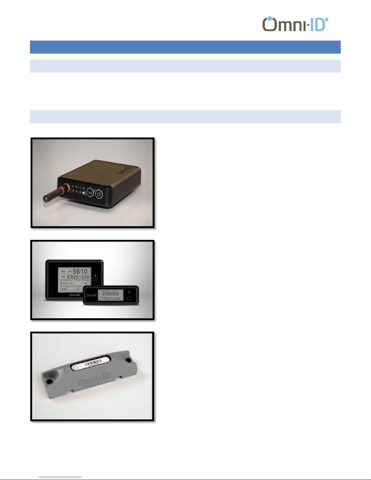
Related Products .....................................................................................................................................................................3
Regulatory Approvals ..............................................................................................................................................................5
Certifications .......................................................................................................................................................................5
Federal Communications Commision Interference Statement ..........................................................................................5
Industry Canada Statement ................................................................................................................................................6
European R&TTE Directive 1999/5/EC Statement ..............................................................................................................6
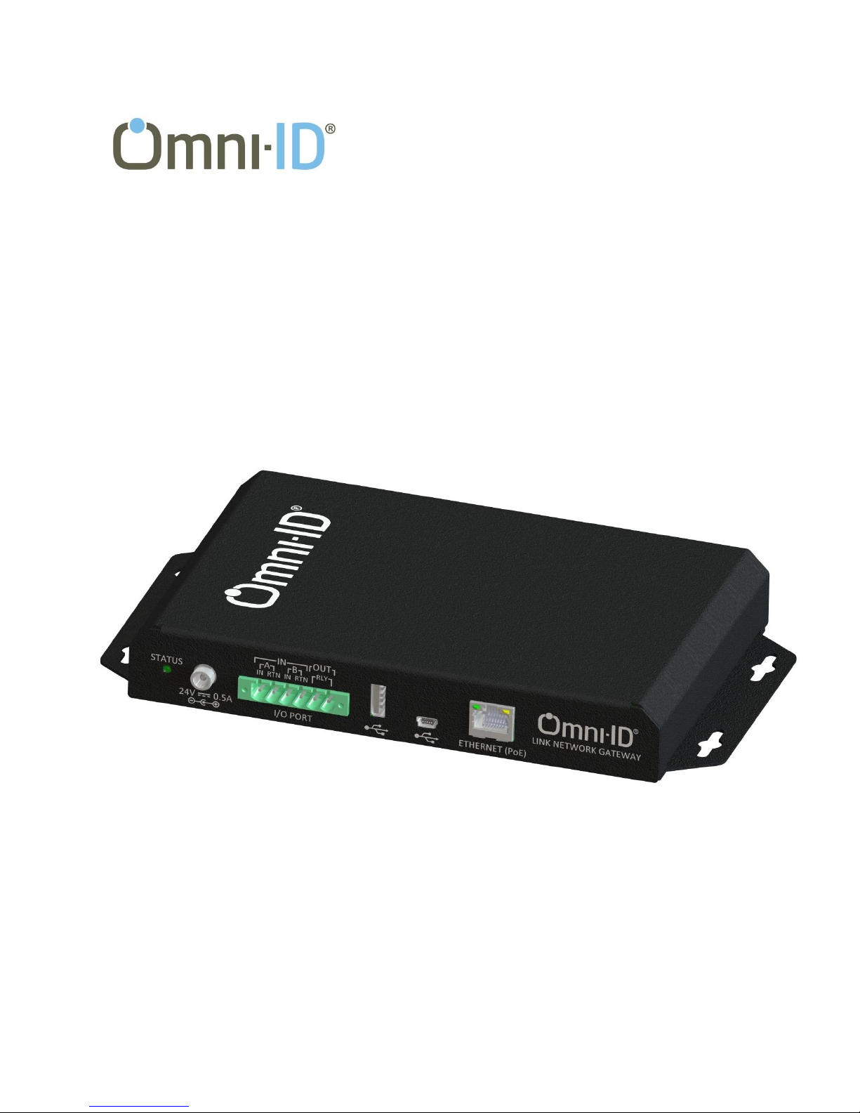
2. The Link Network Gateway .................................................................................................................................................7
Configurations .........................................................................................................................................................................7
Interfaces.................................................................................................................................................................................7
Power ..................................................................................................................................................................................7
I/O Port ...............................................................................................................................................................................7
USB Host..............................................................................................................................................................................8
USB......................................................................................................................................................................................8
Ethernet ..............................................................................................................................................................................8
Radios ......................................................................................................................................................................................8
433MHz Antenna ................................................................................................................................................................9
RFID Antenna ......................................................................................................................................................................9
LED Indicators..........................................................................................................................................................................9
Status ..................................................................................................................................................................................9
Radio Activity ......................................................................................................................................................................9
3. Using the Network gateway..............................................................................................................................................10
Setting the Gateway Address Through the USB Port ............................................................................................................10
Determing the Gateway IP Address Through the Web Server..............................................................................................10
Using the Gateway with TagLab ............................................................................................................................................12

Link Network Gateway User Guide
-2-
4. Specifications ....................................................................................................................................................................15
Physical Specifications...........................................................................................................................................................15
Radio Specifications (RM433V2) ...........................................................................................................................................16
Environmental Specifications ................................................................................................................................................16
5. Customer Support.............................................................................................................................................................17

Link Network Gateway User Guide
-3-
1. INTRODUCTION
ABOUT THIS DOCUMENT
This Guide describes the setup and configuration of the Omni-ID Link Network Gateway and documents its characteristics.
For instructions on using the Gateway with one of Omni-ID’s various software offerings, please refer to the documentation
provided with the specific application.
RELATED PRODUCTS
Link Mobile Gateway
As part of Omni-ID’s ProVIEW and Asset Track system offerings, the
Link Mobile Gateway provides a reliable, portable solution for
communicating with Omni-ID’s families of Power and View tags.
Whether using the simplicity of the USB interface or the wireless
convenience of Bluetooth, the Mobile Gateway can get you up and
running quickly and easily.
View 3 and View 4
As part of Omni-ID’s ProVIEW System Solution, the View 3 and View 4
tags provide an electronic, reusable option to replace paper labels in
cyclic applications. Featuring electrophoretic displays, a rugged form
factor and advanced RF tracking capabilities, these provide an ideal
solution for durable, repetitive labeling in manufacturing and logistics
applications.
Power 400/415
The Omni-ID Power 400 and 415, operating at 433 MHz and 900 MHz,
are rugged active tags capable of tremendous performance while
tracking assets in harsh environments. Overmolded for maximum
durability and providing flexible mounting options, these Power tags
include enough battery capacity for at least 5 years of duty in most
applications. Radio communications penetrate snow/moisture and
provide exceptional distance.

Link Network Gateway User Guide
-4-
Power 60/65
The Power 60 and Power 65 are active tags designed for tracking
personnel and their interactions with tagged assets. Made to be
clipped to clothing or worn around the neck on a lanyard, the Power
60 and 65 are ideal for applications requiring real-time information
about workers.
Power 100/115
The Power 100 and Power 115 are industrial active tags capable of
tremendous performance while tracking for indoor applications.
Constructed of high impact PC/ABS blend including flexible mounting
options, the durability of the Power 100 and 115 includes enough
battery capacity for 4 years of duty in most applications.
Omni-Directional Antenna
The Link Omni-Directional Antenna is the ideal choice for
communicating with Omni-ID’s line of Visual and Power tags. Being
horizontally polarized, it is less susceptible to manmade noise and
able to take advantage of ground reflection gain which
vertical antennas are unable to access.

Link Network Gateway User Guide
-5-
REGULATORY APPROVALS
CERTIFICATIONS
Table 1 - Certifications
Standard
Description
EN55024:2010
Product Family Standard
Immunity
Information Technology Equipment- Immunity
Characteristics-Limits and Methods of Measurement
EN55022:2010 & FCC Part 15
Product Family Standard
Emissions
Information Technology Equipment- Radio Disturbances
Characteristics-Limits and Methods of Measurement
EN55022:2010 & FCC Part 15
Radiated Emissions
EN61000-4-2:2009
Basic test standard
Electrostatic Discharge Immunity
EN61000-4-3:2006+A2:2010
Basic test standard
Radiated Electromagnetic Field Immunity
CAN/CSA- CISPR 22-10/ICES-003
Issue 5
Radiated Emissions
VCCI V3/2012.04 or VCCI-
3/2013.04
Radiated Emissions
CNS:13438:2006
Radiated Emissions
FEDERAL COMMUNICATIONS COMMISION INTERFERENCE STATEMENT
This equipment has been tested and found to comply with the limits for a Class B digital device, pursuant to Part 15 of the
FCC Rules. These limits are designed to provide reasonable protection against harmful interference in a residential
installation. This equipment generates, uses, and can radiate radio frequency energy and, if not installed and used in
accordance with the instructions, may cause harmful interference to radio communications. However, there is no guarantee
that interference will not occur in a particular installation. If this equipment does cause harmful interference to radio or
television reception, which can be determined by turning the equipment off and on, the user is encouraged to try to correct
the interference by one of the following measures:
- Reorient or relocate the receiving antenna.
- Increase the separation between the equipment and receiver.
- Connect the equipment into an outlet on a circuit different from that to which the receiver is connected.
- Consult the dealer or an experienced radio/TV technician for help.

Link Network Gateway User Guide
-6-
This device complies with Part 15 of the FCC Rules. Operation is subject to the following two conditions: (1) This device may
not cause harmful interference, and (2) this device must accept any interference received, including interference that may
cause undesired operation.
FCC Caution: Any changes or modifications not expressly approved by the party responsible for compliance could void the
user's authority to operate this equipment.
INDUSTRY CANADA STATEMENT
This device complies with Industry Canada license-
exempt RSS standard(s). Operation is subject to the
following two conditions: (1) this device may not
cause interference, and (2) this device must accept
any interference, including interference that may
cause undesired operation of the device.
Le présent appareil est conforme aux CNR d'Industrie
Canada applicables aux appareils radio exempts de licence.
L'exploitation est autorisée aux deux conditions suivantes :
(1) l'appareil ne doit pas produire de brouillage, et (2)
l'utilisateur de l'appareil doit accepter tout brouillage
radioélectrique subi, même si le brouillage est susceptible
d'en compromettre le fonctionnement.
To reduce potential radio interference to other users, the antenna type and its gain should be so chosen that the equivalent
isotropic radiated power (e.i.r.p.) is not more than that permitted for successful communication.
EUROPEAN R&TTE DIRECTIVE 1999/5/EC STATEMENT
The radio module enclosed in this product is compliant with ETSI EN 300 328 V1.7.1 (2006-10), EMC, EN 301 489-17 v2.1.1
(2009-02) and the Basic Safety Assessment (BSA) EN 60950-1:2006 (2006-06) and is subject to a Notified Body Opinion. The
modules are approved for use with the antennas listed in the following table.
Table 2 - Approved antennas
Brand
Model Number
Description
Gain (dBi)
COMTELCO
BS450S-B
Vertical Base Station Antenna
4.65
COMTELCO
Y2243-B
YAGI ANTENNA
9.15
Antenna Factor
ANT-433-CW-RH
Helical Whip Antenna
-5.6
Antenna Factor
ANT-433-MHW-SMA
Dipole Antenna
1.2
Omni-ID, Inc.
CP10636
Horizontal Polarized Dipole Antenna
2.15

Link Network Gateway User Guide
-7-
2. THE LINK NETWORK GATEWAY
CONFIGURATIONS
All Network gateways include two radio modules operating at 433 MHz for communication with Omni-ID’s View and Power
Tag families. Additionally, a Gateway can be configured from the factory with an optional RFID reader module capable of
reading any EPC Gen 2 compliant tag as well as the RFID component of the View and Power tags. This enables the device to
become the center of all tag communication with one simple interface and without the cost of additional equipment.
The specific products available are detailed in Table 3 below.
Table 3 –Product Configurations
Part Number
Order Code
Description
CP12035
OMNI-NGW-2
Link Network Gateway, (2) 433 MHz Radio Modules
CP12042
OMNI-NGW-RF-US
Link Network Gateway, (2) 433 MHz Radio Modules, (1) RFID Reader, FCC band
CP12043
OMIN-NGW-RF-EU
Link Network Gateway, (2) 433 MHz Radio Modules, (1) RFID Reader, ETSI band
INTERFACES
Figure 1 - Interface connectors
POWER
The system can operate from any combination of PoE (Power over Ethernet) or DC inputs, and will switch transparently
between them. The DC power input utilizes a 2.5 mm, center pin jack (CUI PJ-066B) which allows for a barrel style connector
for quick attachment or an optional locking ring for more secure connection.
•Mating connector: 2.5 mm ID, 9.5 mm long barrel plug, center positive
•Locking ring thread size: 5/16 - 32 UNEF 2B (e.g. Switchcraft 760K, 765K or equivalent)
The DC supply should be a limited energy source operating at 24V / 0.5A, such as SL Power Electronics model TE10A2403B01.
I/O PORT
The Gateway provides two general purpose inputs and one output, implemented with a TE 796866-6 connector. The pin
assignments are described on the case labeling. Appropriate mating connectors are:
•Right angle –TE 796859-6
•Vertical, left –TE 796861-6
•Vertical, right –TE 796863-6

Link Network Gateway User Guide
-8-
Input
•Two optically isolated inputs
•24V nominal, 50V maximum (protected from
reverse connection)
•Input impedance: 5.2K
•Minimum “on” voltage: 19V @ 4.4mA
•Maximum “off” voltage: TBD
•Response time:
oLow to High transition: 40 sec
oHigh to Low transition: 400 sec
Output
•One output, normally open
•Contacts rated to 2A, 24VDC
•Rated for 10 million operations
•Relay coil: 178 Ohm, 140mW nominal operating power
•Relay coil current consumption at 24VDC input: 7mA
USB HOST
This port is reserved for future expansion.
USB
The USB port is provided for configuring the network settings on the Gateway. Refer to Chapter 3 for details of this interface.
ETHERNET
The Gateway supports 100BaseT ethernet communication using a standard RJ45 jack. This connector includes integrated Link
and Activity status LED’s.
The Gateway can be powered through this connection using an IEEE 802.3af compliant PoE source (44-57VDC).
The Gateway supports both IPv4 and IPv6 addressing.
RADIOS
Figure 3 - Antenna connectors, standard product
Figure 2 - Input circuit diagram

Link Network Gateway User Guide
-9-
Figure 4 - Antenna connectors, RFID equipped product
433MHZ ANTENNA
Each Gateway is equipped with two 433 MHz radio modules, labeled “A” and “B” as shown in Figure 4 above. These utilize
standard SNA connectors.
RFID ANTENNA
For units so equipped, there will be a connector for the embedded RFID reader in the center of the panel as shown in
figure 4.
LED INDICATORS
STATUS
The System Status LED is located immediately to the left of the power connector (refer to Figure 1). This multi-colored
indicator will reflect the overall status of the Gateway as follows:
Color
Function
Red
Solid or flashing indicates an error condition. However, a momentary period of solid
red immediately on power up is normal.
Blue
Flashes at a 50% duty cycle when system is booting up. Blinks in a "heartbeat"
pattern when shutting down or restarting.
Green
Flashes when system is running.
Red/Green
Flashes alternately red and green during firmware upgrade.
RADIO ACTIVITY
Immediately adjacent to each antenna port is a bi-color LED which indicates the RF activity on that channel:
Color
Function
Red
Flashes when a message is transmitted on the 433 MHz radio
Green
Flashes when a message is received on the 433 MHz radio

Link Network Gateway User Guide
-10-
3. USING THE NETWORK GATEWAY
SETTING THE GATEWAY ADDRESS THROUGH THE USB PORT
The first step in using the device is to determine the Gateway’s IP address. This could be a static address that you have
assigned or a dynamic one assigned by a DHCP server. Obtaining or setting this address requires connecting to the Gateway
through its USB port (refer to Figure 1 - Interface connectors). The simplest way is to use a terminal emulation program such
as PuTTY (available for free download at http://sourceforge.net/projects/puttymanager). Configure the terminal to
communicate at a baud rate of 115200 with 8 data bits, 1 stop bit and no parity.
When you receive the login prompt, use customer as both the username and password. The Gateway will then display the
network settings as the example below shows:
From this menu you can configure the IP address for the Gateway by choosing ‘C’ to configure and then ‘I’ for IP address. You
may then choose DHCP (the factory default) or static if you wish to assign an address. Make note of the address and restart
the Gateway if prompted.
DETERMING THE GATEWAY IP ADDRESS THROUGH THE WEB SERVER
In addition to the USB access described above, configuration information about the Gateway can be obtained using its built-
in web server. Simply point any web browser to the Gateway’s hostname and a status page will be displayed. The unit’s
default hostname is link-xx-xx-xx where the xx’s are replaced by the last three bytes of the device’s MAC address. For
example, if the MAC address of a unit is 9C-61-1D-00-00-02, the hostname would be link-00-00-02. Entering link-00-00-
02.local into the browser’s address field will result in the following page being displayed:

Link Network Gateway User Guide
-11-
Clicking on the Network tab, would then display the details of the unit’s IP addressing, both for IPv4 and IPv6 network
configurations.

Link Network Gateway User Guide
-12-
USING THE GATEWAY WITH TAGLAB
TagLab is a development tool which is provide with the ProVIEW Starter Kits, allowing for simple communication with the
Power and View tag families. It provides a quick means for testing and evaluating Omni-ID equipment in a specific
environment for system development is complete.
To connect to the Gateway in the TagLab application, select ‘File | New Network Gateway’. The following screen will be
shown:
Enter the address of the Gateway in the “Gateway IP Addr” field. The Gateway IP Service Port will default to 80. Leave this
value. When you press the Ping button, the application will check to see if there is a device on the network at that address
and then ascertain whether or not the device is an Omni-ID Gateway. When successful, you will see a message like this:

Link Network Gateway User Guide
-13-
Now that you’ve told TagLab the address of the Gateway, you need to configure the Gateway to send data to the PC on which
TagLab is running. This is done by pressing the Auto-Config Gateway Addr button. When successful, the display should look
like the following:
Click OK and the On Screen Detailed View will be displayed (see the upcoming section on TagLab Views for a description). At
the bottom of the screen you should see the address of your Gateway and its status. Both status lights should be green.
If your Gateway is not connected, or is connected but receives no pings or tag reads, you need to ensure that there is no
firewall preventing communication. To easily do this, go to the ‘Tools | Configure Network Gateway’ menu. You will be shown
the address and port that the Gateway should be using (these were already set in the Gateway in the previous step) as well
as more Gateway configuration information. Click on the Check Firewall button at the bottom of this window. If there is no
issue with the firewall, the returned status will state that the firewall is open:
If there is a firewall in the way, you will be given the opportunity to open the firewall for the Service Endpoint Port:

Link Network Gateway User Guide
-14-
After opening the port, you will need to restart TagLab in order for the changes to take effect.
Note: TagLab is only able to detect and open Windows Firewall. If a third-party firewall is installed on your
system, please refer to its documentation for disabling or opening ports.
For a complete description of the features of TagLab, please refer to the ProVIEW Starter Kit User Guide available as part of
the View Starter Kit and the Power Starter Kit.

Link Network Gateway User Guide
-15-
4. SPECIFICATIONS
PHYSICAL SPECIFICATIONS
Material
Galvanized cold-rolled steel
Size (mm)
231 x 131 x 29
Size (in)
9.09 x 5.17 x 1.15
Weight (g)
868
Weight (oz)
31 (1 lb 15 oz)

Link Network Gateway User Guide
-16-
RADIO SPECIFICATIONS (RM433V2)
The Link Network Gateway incorporates Omni-ID’s RM433V2 433 MHz radio module. Its characteristics are described in the
following table:
Typical RF Characteristics
Notes
Rx Sensitivity
-100 dBm
Nominal for .1% BER
Tx Power
+5dBm
433.164 –434.784 MHz
Max. Input Signal
10 dBm
RSSI Range
-100 to -10 dBm
RF Port Impedance
50 ohms
433.164 –434.784 MHz
VSWR (max)
2:1
433.164 –434.784 MHz
ENVIRONMENTAL SPECIFICATIONS
Operating Temperature
-20C to +60C
Ingress Protection
IP50
Warranty
1 year

Link Network Gateway User Guide
-17-
5. CUSTOMER SUPPORT
Information about Omni-ID’s complete line of RFID products can be found on our website: www.omni-id.com.
The contents of this document are subject to change without notice. OMNI-ID, inc. reserves the right to make changes,
without notice, in the products, including circuits and/or software, described or contained therein. Information contained in
this document regarding device applications and the like is intended through suggestion only and may be superseded by
updates. It is your responsibility to ensure that your application meets with your specifications.
102017
This manual suits for next models
2
Table of contents
Popular Gateway manuals by other brands

Nokia
Nokia FastMile 2.1.04 Product overview

Moxa Technologies
Moxa Technologies MGate MB3170 Quick installation guide

Wifx
Wifx Lorix One quick start guide

EuroTech Communication
EuroTech Communication GSM gateway user manual

Juniper
Juniper SRX550 quick start guide

AudioCodes
AudioCodes Mediant 500L MSBR user manual