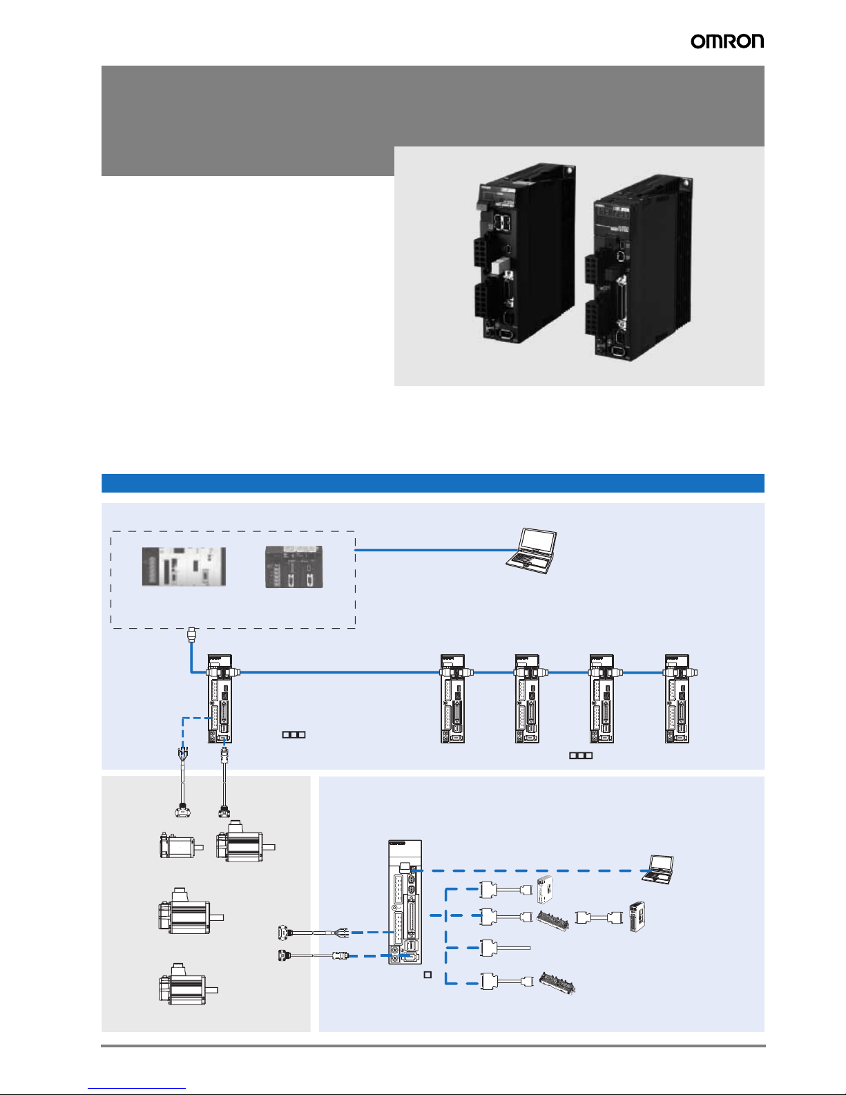
Omron ACCURAX-G5 - 2 User manual

1Accurax G5 servo drive
R88D-KN@@@-ML2, R88D-KT@
Accurax G5 servo drive
Accurate motion control in a compact size
servo drive family. MECHATROLINK-II
motion bus and safety built-in.
• MECHATROLINK-II and Analog/ Pulse servo drive
models
• Safety conforming ISO13849-1 Performance Level
D
• High-response frequency of 2 kHz
• High resolution serial encoder for greater accuracy
provided by 20 bits encoder
• External encoder input for full close loop
• Real time auto-tuning
• Advanced tuning algorithms (Anti-vibration function,
torque feedforward, disturbance observer)
Ratings
• 230 VAC Single-phase 100 W to 1.5 kW (8.59 Nm)
• 400 VAC three-phase 600 W to 5 kW (28.7 Nm)
System configuration
Servo Motor
3000 rpm (50 W-5 kW)
Servo Motor
2000 rpm (400 W-5 kW)
Servo Motor
1000 rpm (900 W-3 kW)
MECHATROLINK-II
Terminator
Personal computer
software: CX-One
Accurax G5 ML-II Servo Drives
MECHATROLINK-II control
Encoder cable
Power cable
Personal computer:
Software CX-One
Te r m i n al block
for Servo drive I/O
general purpose
signals
Unit
Position control unit
Motion control unit
General purpose cable
Open Analog/pulse control
Power cable
Encoder cable
Accurax G5 Analog/pulse
Servo Drive
TJ1-M
C
04
/
1
6
TJ1-M
C
04
/
1
6
C
J1W-M
C
H72
C
J1W-M
C
H72
C
J1W-N
C
F71
C
J1W-N
C
F71
R88D-KT
R88D-KN -ML2
R88D-KN -ML2

2AC servo systems
Servo drive
Servo motor supported
Accurax G5 rotary servo motor Accurax G5 servodrive
Voltage Speed Rated torque Capacity Model MECHATROLINK-II model Analog/Pulse model
230V 400V 230V 400V
230 V 3000 min-1 0.16 Nm 50 W R88M-K05030(H/T)-@R88D-KN01H-ML2 - R88D-KT01H -
0.32 Nm 100 W R88M-K10030(H/T)-@R88D-KN01H-ML2 - R88D-KT01H -
0.64 Nm 200 W R88M-K20030(H/T)-@R88D-KN02H-ML2 - R88D-KT02H -
1.3 Nm 400 W R88M-K40030(H/T)-@R88D-KN04H-ML2 - R88D-KT04H -
2.4 Nm 750 W R88M-K75030(H/T)-@R88D-KN08H-ML2 - R88D-KT08H -
3.18 Nm 1000 W R88M-K1K030(H/T)-@R88D-KN15H-ML2 - R88D-KT15H -
4.77 Nm 1500 W R88M-K1K530(H/T)-@R88D-KN15H-ML2 - R88D-KT15H -
400 V 2.39 Nm 750 W R88M-K75030(F/C)-@- R88D-KN10F-ML2 - R88D-KT10F
3.18 Nm 1000 W R88M-K1K030(F/C)-@- R88D-KN15F-ML2 - R88D-KT15F
4.77 Nm 1500 W R88M-K1K530(F/C)-@- R88D-KN15F-ML2 - R88D-KT15F
6.37 Nm 2000 W R88M-K2K030(F/C)-@- R88D-KN20F-ML2 - R88D-KT20F
9.55 Nm 3000 W R88M-K3K030(F/C)-@- R88D-KN30F-ML2 - R88D-KT30F
12.7 Nm 4000 W R88M-K4K030(F/C)-@- R88D-KN50F-ML2 - R88D-KT50F
15.9 Nm 5000 W R88M-K5K030(F/C)-@- R88D-KN50F-ML2 - R88D-KT50F
230 V 2000 min-1 4.77 Nm 1000 W R88M-K1K020(H/T)-@R88D-KN10H-ML2 - R88D-KT10H -
7.16 Nm 1500 W R88M-K1K520(H/T)-@R88D-KN15H-ML2 - R88D-KT15H -
400 V 1.91 Nm 400 W R88M-K40020(F/C)-@- R88D-KN06F-ML2 - R88D-KT06F
2.86 Nm 600 W R88M-K60020(F/C)-@- R88D-KN06F-ML2 - R88D-KT06F
4.77 Nm 1000 W R88M-K1K020(F/C)-@- R88D-KN10F-ML2 - R88D-KT10F
7.16 Nm 1500 W R88M-K1K520(F/C)-@- R88D-KN15F-ML2 - R88D-KT15F
9.55 Nm 2000 W R88M-K2K020(F/C)-@- R88D-KN20F-ML2 - R88D-KT20F
14.3 Nm 3000 W R88M-K3K020(F/C)-@- R88D-KN30F-ML2 - R88D-KT30F
19.1 Nm 4000 W R88M-K4K020(F/C)-@- R88D-KN50F-ML2 - R88D-KT50F
23.9 Nm 5000 W R88M-K5K020(F/C)-@- R88D-KN50F-ML2 - R88D-KT50F
230 V 1000 min-1 8.59 Nm 900 W R88M-K90010(H/T)-@R88D-KN15H-ML2 - R88D-KT15H -
400 V 8.59 Nm 900 W R88M-K90010(F/C)-@R88D-KN15F-ML2 - R88D-KT15F
19.1 Nm 2000 W R88M-K2K010(F/C)-@R88D-KN30F-ML2 - R88D-KT30F
28.7 Nm 3000 W R88M-K3K010(F/C)-@R88D-KN50F-ML2 - R88D-KT50F
Type designation
Accurax G5 Seriesservo drive
R88D-KN01H-ML2
Drive Type
T: Analog/pulse type
N: Network type
Voltage Code
230 V
Output
Capacity and Voltage
100 W
400 V
01H
02H
04H
08H
10H
15H
06F
10F
15F
20F
30F
50F
400 W
200 W
750 W
1 kW
1.5 kW
600 W
1.0 kW
1.5 kW
2.0 kW
3.0 kW
5.0 kW
Model
Blank: Analog/pulse type
ML2: MECHATROLINK-II comms

Accurax G5 servo drive 3
Single-phase, 230 V
Three-phase, 400 V
Servo drive specifications
Servo drive type R88D-K@01H@02H@04H@08H@10H@15H@
Applicable
servo motor
R88M-K@05030(H/T)@20030(H/T)@ 40030(H/T)@75030(H/T)@1K020(H/T)@ 1K030(H/T)@
10030(H/T)@- - - - 1K530(H/T)@
-----1K520(H/T)@
-----90010(H/T)@
Basic specifications
Max. applicable motor capacity W 100 200 400 750 1000 1500
Continuous output current Arms 1.2 1.6 2.6 4.1 5.9 9.4
Input power Main circuit Single-phase/3-phase, 200 to 240 VAC + 10 to -15% (50/60 Hz)
Supply Control circuit Single-phase, 200 to 240 VAC + 10 to -15% (50/60 Hz)
Control method IGBT-driven PWM method, sinusoidal drive
Feedback Serial encoder (incremental/absolute value)
Conditions
Usage/storage temperature 0 to +55 °C / -20 to 65 °C
Usage/storage humidity 90% RH or less (non-condensing)
Altitude 1000m or less above sea level
Vibration/shock resistance (max.) 5.88 m/s210-60 Hz (Continuous operation at resonance point is not allowed) / 19.6 m/s2
Configuration Base mounted
Approx. weight Kg 0.8 1.1 1.6 1.8
Servo drive type R88D-K@06F-@10F-@15F-@20F-@30F-@50F-@
Applicable
servo motor
R88M-K@40020(F/C)-@75030(F/C)-@1K030(F/C)-@2K030(F/C)-@3K030(F/C)-@4K030(F/C)-@
60020(F/C)-@1K020(F/C)-@1K530(F/C)-@2K020(F/C)-@3K020(F/C)-@5K030(F/C)-@
- - 1K520(F/C)-@-2K010(F/C)-@4K020(F/C)-@
- - 90010(F/C)-@- - 5K020(F/C)-@
- - - - 3K010(F/C)-@
Basic specifications
Max. applicable motor capacity kW 0.6 1.0 1.5 2.0 3.0 5.0
Continuous output current Arms 2.9 4.7 6.7 9.4 16.5
Input power Main circuit 3-phase, 380 to 480 VAC + 10 to -15% (50/60Hz)
Supply Control circuit 24 VDC ±15%
Control method IGBT-driven PWM method, sinusoidal drive
Feedback Serial encoder (incremental/absolute value)
Conditions
Usage/storage temperature 0 to +55 °C / -20 to +65 °C
Usage/storage humidity 90% RH or less (non-condensing)
Altitude 1000 m or less above sea level
Vibration/shock resistance 5.88 m/s210-60 Hz (Continuous operation at resonance point is not allowed) / 19.6 m/s2
Configuration Base mounted
Approx. weight Kg 1.9 2.7 4.7

4AC servo systems
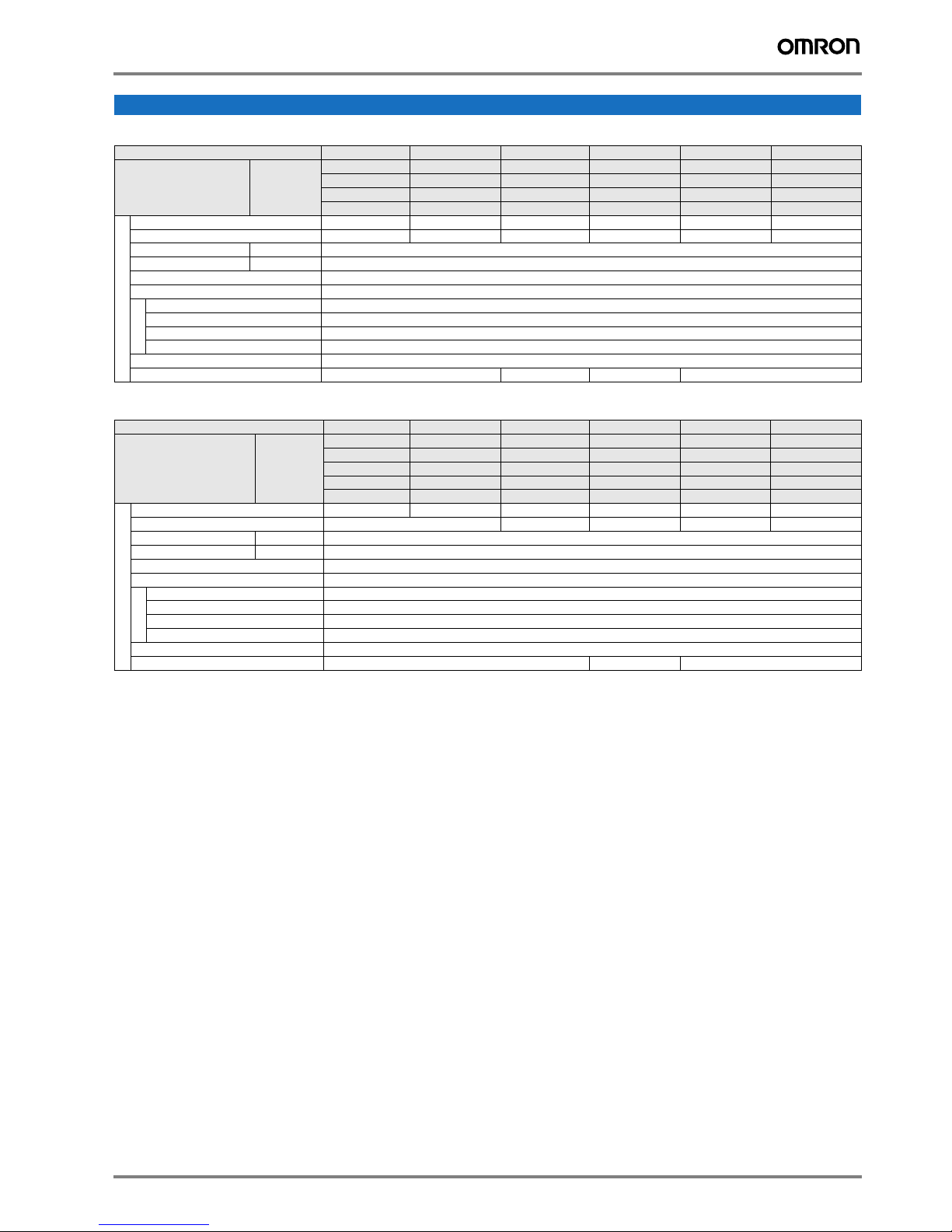
General specifications (for MECHATROLINK-II servo drives)
General specifications (for analog/pulse servo drives)
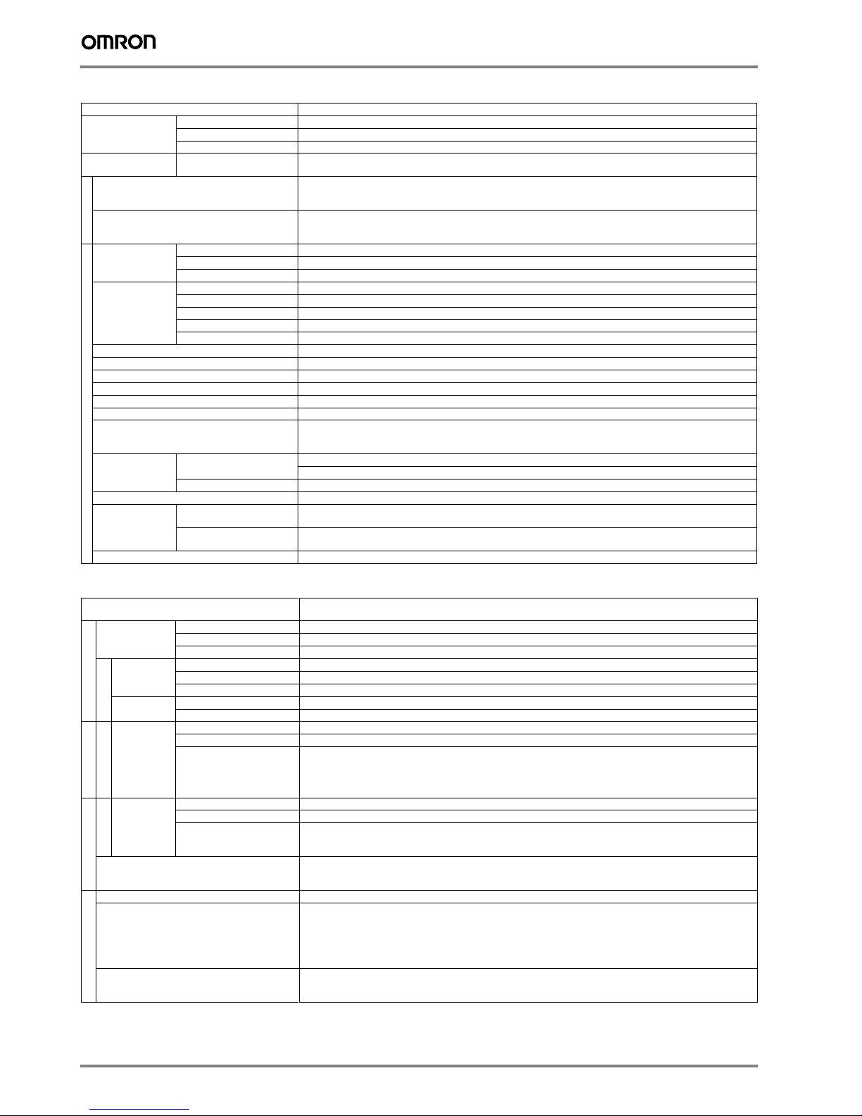
Control mode Position control, velocity control, torque control, full-closed control.
Performance Frequency characteristics 2 kHz
Speed zero clamp Preset velocity command can be clamped to zero by the speed zero clamp input.
soft start time setting 0 to 10 s (acceleration, deceleration can be set separately).
Command input MECHATROLINK-II
communication
MECHATROLINK-II commands (for sequence, motion, data setting/reference, monitor, adjustment and other
commands)
I/O signal
Sequence input signal - Multi-function input x 8 by parameter setting (forward/reverse drive prohibition, emergency stop, external latch,
origin proximity, forward/reverse torque limit, general purpose monitor input).
Sequence output signal It is possible to output three types of signal form incl.: brake release, servo ready, servo alarm, positioning com-
plete, motor rotation speed detection, torque limit detection, zero speed detection, speed coincidence detection,
warning, position command status, speed limit detection, alarm ouput, speed command status.
Integrated functions
USB
Communications
Interface Personal computer/ Connector mini-USB
Communications standard Compliant with USB 2.0 standard
Function Parameter setting and status monitoring
MECHATROLINK-
II communications
Communications protocol MECHATROLINK-II
Station address 41H to 51 FH (max. number of slaves: 30)
Tranmission speed 10 Mbps
Transmission cycle 1, 2 & 4 ms
Data length 17-bytes and 32-bytes
Automatic load inertia detection Automatic motor parameter setting. One parameter rigidity setting.
Dynamic brake (DB) Built-in. Operates during main power OFF, servo alarm, servo OFF or overtravel.
Regenerative processing Internal resistor included in models from 600 W to 5 kW. Regenerative resistor externally mounted (option).
Overtravel (OT) prevention function DB stop, deceleration stop or coast to stop during P-OT, N-OT operation
Encoder divider function Optional division possible
Protective functions Overcurrent, overvoltage, undervoltage, overspeed, overload, encoder error, overheat...
Analog monitor functions for supervision Analog monitor of motor speed, speed reference, torque reference, command following error, analog input...
The monitoring signals to output and their scaling can be specified with parameters.
Number of channels: 2 (Output voltage: ±10V DC)
Panel operator Display functions 2-digit 7-segment LED display shows the drive status, alarm codes, parameters...
MECHATROLINK-II communications status LED indicator (COM)
Switches 2 x rotary switches for setting the MECHATROLINK-II node address
CHARGE lamp Lits when the main circuit power supply is turned ON.
Safety terminal Functions Safety Torque OFF function to cut off the motor current and stop the motor. Output signal for failure monitoring
function.
Conformed standards EN ISO13849-1:2008 (PL- d, Performance Level d), IEC61800-5 -2:2007 (function STO, Safe Torque OFF),
EN61508:2001 (Safety Integrity Level 2, SIL2), EN954-1:1996 (CAT3).
External encoder feedback Serial signal and line-driver A-B-Z encoder for full-close control
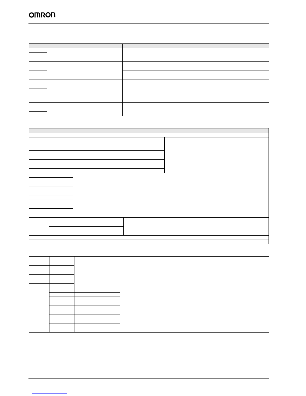
Control mode 7 modes selectables by parameter: (1) position control, (2) velocity control, (3) torque control, (4) position/velocity
control, (5) position/torque control, (6) velocity/torque control and (7) full-closed control.
Speed/torque control
Performance
Frequency characteristics 2 kHz
Speed zero clamp Preset velocity command can be clamped to zero by the speed zero clamp input.
Soft start time setting 0 to 10 s (acceleration, deceleration can be set separately). S-curve acceleration/deceleration is also available.
Input signal
Speed control Speed reference voltage 6 VDC at rated speed: set at delivery (the scale and polarity can be set by parameters)
Torque limit 3 VDC at rated torque (torque can be limited separately in positive/negative direction).
Preset speed control Preset speed is selectable from 8 internal settings by digital inputs.
Torque control Torque reference voltage 3 VDC at rated torque: set at delivery (the scale and polarity can be set by parameters).
Speed limit Speed limit can be set by parameter.
Position control
Input signal
Command
pulse
Input pulse type Sign + pulse train, 90° phase displacement 2-phase pulse (A-phase+ B-phase) or CCW/CW pulse train
Input pulse frequency 4 Mpps max. (200 Kpps max. at open collector).
Command pulse scaling
(Electronic Gear)
Applicable scaling ratio: 1/1000 - 1000
Any value of 1-2020 can be set for numerator (encoder resolution) and denominator (command pulse resolution
per motor revolution). The combination has to be within the range shown above.
Full-closed control
Input signal
Command
pulse
Input pulse type Sign + pulse train, 90° phase displacement 2-phase pulse (A-phase+ B-phase) or CCW/CW pulse train
Input pulse frequency 4 Mpps max. (200 Kpps max. at open collector).
Command pulse scaling
(Electronic Gear)
Applicable scaling ratio: 1/1000 - 1000
Any value of 1-2020 can be set for numerator (encoder resolution) and denominator (command pulse resolution).
The combination has to be within the range shown above.
External encoder scaling Applicable scaling ratio: 1/20 - 160
Any value of 1-2020 can be set for numerator (encoder resolution) and denominator (external encoder resolution
per motor revolution). The combination has to be within the range shown above.
I/O signal
Position signal output A-phase, B.phase, Z-phase line driver output and Z-phase open-collector output.
Sequence input signal - Multi-function input x 10 by parameter setting (servo ON, control mode switching, forward/reverse drive prohi-
bition, vibration filter switching, gain switching, electronic gear switching, error counter reset, pulse prohibition,
alarm reset, internal speed selection, torque limit switching, zero speed, emergency stop, inertia ratio switching,
velocity/torque command sign).
- Dedicated input x 1 (SEN: sensor ON, ABS data request).
Sequence output signal It is possible to output four types of signal form incl.: brake release, servo ready, servo alarm, positioning com-
plete, motor rotation speed detection, torque limit detection, zero speed detection, speed coincidence detection,
warning, position command status, speed limit detection, speed command status.

Accurax G5 servo drive 5
Servo drive part names
Note: the above pictures show 230V servo drives models only. The 400V servo drives have DC power input terminals for control circuit instead of
L1C and L2C terminals.
Integrated functions
USB
Communications
Interface Personal computer/ Connector mini-USB
Communications standard Compliant with USB 2.0 standard
Function Parameter setting and status monitoring
Automatic load inertia detection Automatic motor parameter setting. One parameter rigidity setting.
Dynamic brake (DB) Built-in. Operates during main power OFF, servo alarm, servo OFF or overtravel.
Regenerative processing Internal resistor included in models from 600 W to 5 kW. Regenerative resistor externally mounted (option).
Overtravel (OT) prevention function DB stop, deceleration stop or coast to stop during P-OT, N-OT operation
Encoder divider function Optional division possible
Electronic gearing (Numerator/Denominator) Up to 4 electronic gear numerators by combining with inputs.
Internal speed setting function 8 speeds may be set internally
Protective functions Overcurrent, overvoltage, undervoltage, overspeed, overload, encoder error, overheat...
Analog monitor functions for supervision Analog monitor of motor speed, speed reference, torque reference, command following error, analog input...
The monitoring signals to output and their scaling can be specified by parameters.
Number of channels: 2 (Output voltage: ±10V DC)
Panel operator Display functions 6-digit 7-segment LED display shows the drive status, alarm codes, parameters...
Panel operator keys Used to set/monitor parameters and drive condition (5 key switches).
CHARGE lamp Lits when the main circuit power supply is turned ON.
Safety terminal Functions Safety torque OFF function to cut off the motor current and stop the motor. Output signal for failure monitoring
function.
Conformed standards EN ISO13849-1:2008 (PL- d, Performance Level d), IEC61800-5 -2:2007 (function STO, Safe Torque OFF),
EN61508:2001 (Safety Integrity Level 2, SIL2), EN954-1:1996 (CAT3).
External encoder feedback Serial signal and line-driver A-B-Z encoder for full-close control
Expansion connector Serial bus for option board
Display area
Operation area
USB connector (CN7)
Expansion connector (CN3)
Monitor connector (CN5)
Motor connection
terminals(U, V and W)
Control circuit
power supply terminals
(L1C and L2C)
Main circuit
power supply terminals
(L1, L2, and L3)
External Regeneration
Resistor connection
terminals(B1, B2 and B3)
Protective ground terminals
Control I/O connector (CN1)
- 50 pins-
Safety connector (CN8)
External encoder connector (CN4)
Encoder connector (CN2)
Charge lamp
Display area
Address number switches
MECHATROLINK-II connector (CN6)
Monitor connector (CN5)
Motor connection
terminals(U, V and W)
Control circuit
power supply terminals
(L1C and L2C)
Main circuit
power supply terminals
(L1, L2, and L3)
External Regeneration
Resistor connection
terminals(B1, B2 and B3)
Protective ground terminals
Control I/O connector (CN1)
- 26 pins-
Safety connector (CN8)
External encoder connector (CN4)
Encoder connector (CN2)
Charge lamp
USB connector (CN7)
MECHATROLINK-II servo drivesAnalog/pulse servo drives

6AC servo systems
I/O specifications
Terminals specifications (for all drives)
I/O signals (CN1) - Input signals (for MECHATROLINK-II servo drives)
I/O signals (CN1) - output signals (for MECHATROLINK-II servo drives)
Symbol Name Function
L1 Main power supply input terminal AC power input terminals for the main circuit
Note: for single-phase servo drives connect the power supply input to L1 and L3.
L2
L3
L1C Control power supply input terminal AC power input terminals for the control circuit
(for 200V single/three-phase servo drives only).
L2C
24 V DC power input terminals for the control circuit
(for 400V three-phase servo drives only).
0 V
B1 External regeneration resistor connection terminals Servo drives below 750W: no internal resistor is connected. Leave B2 and B3 open.
Connect an external regenerative resistor between B1 and B2.
Servo drives from 750W to 5 kW: short-circuit in B2 and B3 for internal regenerative resistor. If the
internal regenerative resistor is insufficient, connect an external regenerative resistor between B1 and
B2 and remove the wire between B2 and B3.
B2
B3
U Servo motor connection terminals Terminals for outputs to the servomotor.
V
W
Pin No. Signal name Function
6 I-COM ± pole of external DC power. The power must use 12V-24V (±5%)
5 E-STOP Emergency stop The signal name shows the factory setting. The function can be
changed by parameter setting.
7 P-OT Forward run prohibited
8 N-OT Reverse run prohibited
9 DEC Origin proximity
10 EXT3 External latch input 3
11 EXT2 External latch input 2
12 EXT1 External latch input 1
13 SI-MON0 General purpose monitor input 0
14
BTP-I Connecting pin for the absolute encoder backup battery. Do not connect when a battery is connected to the encoder cable (CN2
connector).
15 BTN-I
17 - Terminals not used. Do not connect.
18 -
19 -
20 -
21 -
22 -
23 -
24 -
- PCL Forward torque limit The function of input signals allocated to pins 5 and 7 to 13 can be changed with these options by
parameters settings.
NCL Reverse torque limit
SI-MON1 General-purpose monitor input 1
SI-MON2 General-purpose monitor input 2
Shell FG Shield ground. Connected to frame ground if the shield wire of the I/O signal cable is connected to the connector shell.
16 GND Signal ground. It is insulated with power supply (I-COM) for the control signal in the servo drive.
Pin No. Signal name Function
1 BRK-OFF+ External brake release signal
2BRK-OFF
25 S-RDY+ Servo ready: ON when there is no servo alarm and control/main circuit power supply is ON
26 S-RDY-
3 ALM+ Servo alarm: Turns OFF when an error is detected
4ALM-
- INP1 Position complete output 1 The function of output signals allocated to pins 1,2, 25 and 26 can be changed with these options by
parameters settings
AT-SPEED Speed complete
T_LIM Torque limit
ZSP Zero speed
V-COIN Speed coincidence
INP2 Position complete output 2
WARN1 Warning 1
WARN2 Warning 2
DEN Origin proximity
V_LIM Speed limit

Accurax G5 servo drive 7
I/O signals (CN1) - Input signals (for analog/pulse servo drives)
Pin No. Control mode Signal name Function
1 Position/
Full close loop
+24 VCW Reference pulse input for line driver and open collector according to parameter setting.
Input mode:
Sign + pulse string
Reverse/forward pulse (CCW/CW pulse)
Two-phase pulse (90° phase differential)
3+CW
4-CW
2 +24 VCW
5+CCW
6 -CCW
44 +CWLD Reference pulse input for line driver only.
Input mode:
Reverse/forward pulse (CCW/CW pulse)
45 -CWLD
46 +CCWLD
47 -CCWLD
14 Speed REF Speed reference input: ±10 V/rated motor speed (input gain can be modified using a parameter).
Torque TREF1 Torque reference input: ±10 V/rated motor torque (input gain can be modified using a parameter).
VLIM Speed limit input: ±10 V/rated motor speed (input gain can be modified using a parameter).
15 - AGND1 Analog signal ground
16 Torque TREF2 Torque reference input: ±10 V/rated motor torque (input gain can be modified using a parameter).
Position/Speed
Full close loop
PCL Forward torque limit input: ±10 V/rated motor torque (input gain can be modified using a parameter).
18 NCL Reverse torque limit input: ±10 V/rated motor torque (input gain can be modified using a parameter).
17 - AGND1 Analog signal ground
7
Common +24 VIN Control power supply input for sequence signals: users must provide the +24 V power supply (12 to 24 V).
29 RUN Servo ON: this turn ON the servo.
26 Position/Full
close loop DFSEL1 Vibration filter switching 1 Enables vibration filter according parameter setting.
27 Common GSEL Gain switching Enables gain value according parameter setting.
28 Position/Full
close loop GESEL1 Electronic gear switching 1 Switches the numerator fro electronic gear ratio.
Speed VSEL3 Internal speed selection 3 Input to select the desired speed setting during internally speed operation.
The speed selecton is combining this input with VSEL1 and VSEL2 inputs.
30 Position/Full
close loop ECRST Error counter reset input. Resets the position error counter.
Speed VSEL2 Internal speed selection 2 Input to select the desired speed setting during internally speed operation.
The speed selecton is combining this input with VSEL1 and VSEL3 inputs.
31 Common RESET Alarm reset input. Release the alarm status. The error counter is reset when the alarm is reset.
32
Position/
Speed/Torque
TVSEL Control mode switching
33
Position IPG Pulse prohibition input. Digital input to inhibit the position reference pulse.
Speed VSEL1 Internal speed selection 1 Input to select the desired speed setting during internally speed operation.
The speed selecton is combining this input with VSEL2 and VSEL3 inputs.
8Coomon NOT Reverse run prohibited Overtravel prohibited: stops servomotor when movable part travels beyond the
allowable range of motion.
9 POT Forward run prohibited
20 Position/
Speed/Torque
SEN Sensor ON input. Initial data request signal when using an absolute encoder.
13 SENGND Sensor ON signal ground.
42
Common
BAT (+) Backup battery connection terminals when the absolute encoder power is interrupted. Do not connect when a absolute
encoder battery cable for backup is used.
43 BATGND (-)
50 FG Frame ground
- - TLSEL Torque limit switch The function of input signals allocated to pins 8,9 and 26 to 33 can be changed with
these options by parameters settings
DFSEL2 Vibration filter switching 2
GESEL2 Electronic gear switching 2
VZERO Zero speed
VSIGN Speed command signal
TSIGN Torque command signal
E-STOP Emergency stop
JSEL Inertia ratio switching
12 - Terminals not used. Do not connect.
40 -
41 -
Position
↔
speed
Position
↔
torque
To r que
↔
speed
Enablescontrol mode switching

8AC servo systems
I/O signals (CN1) - output signals (for analog/pulse servo drives)
Encoder connector (CN2) - (for all servo drives)
External encoder connector (CN4) - (for all servo drives)
Monitor connector (CN5) - (for all servo drives)
Pin No. Control mode Signal name Function
21 Position/
Full close loop
+A Encoder phase A+ Encoder signals (or external scale signals during full closing control) are output according En-
coder Dividing Numerator parameter.
This is the line-driver output (equivalent to R422). The maximum output frequency is 4 Mbps.
Phase Z is output for encoder signals (or external scale signals during full closing control). This
is the line-driver output (equivalent to R422).
22 -A Encoder phase A-
48 +B Encoder phase B+
49 -B Encoder phase B-
23 +Z Encoder phase Z+
24 -Z Encoder phase Z-
19 ZEncoder phase-Z output Phase Z is output for encoder signals (or external scale signals during full closing control).
Open-collector output.
25 ZCOM Encoder phase-Z common
11 Common BKIR Brake release signal output Timing signal for operating the electromagnetic brake on a motor.
10 BKIRCOM
35 READY Servo ready: ON if there is not servo alarm when the control/main circuit power supply is turned ON.
34 READYCOM
37 /ALM Servo alarm: turns OFF when an error is detected.
36 ALMCOM
39 Speed/torque TGON Motor rotation speed detection. This output turns ON when the motor rotation speed reaches the speed set in a parameter.
39 Position/
Full close loop
INP1 Positioning complete output 1: turns ON when position error is equal to setting parameter.
38 INP1COM
- - INP2 Position complete output 2 The function of output signals allocated to pins 11,10, 34 to 39 can be changed with these op-
tions by parameters settings.
P-CMD Position command status
ZSP Zero speed
WARN1 Warning 1
WARN2 Warning 2
ALM-ATB Alarm output
VCMP Speed conformity output
V-CMD speed command status
V-LIMIT Speed limit detection
T-LIMIT Torque limit detection
Pin No. Signal Name Function
1 E5V Encoder power supply + 5 V
2 E0V Encoder power supply ground
3 BAT+ Battery + (used only with absolute encoder)
4 BAT– Battery – (used only with absolute encoder)
5 PS+ Encoder serial signal input (+phase)
6 PS– Encoder serial signal input (-phase)
Shell FG Shield ground
Pin No. Signal Name Function
1 E5V External scale power supply output. Use at 5.2V +/-5% and at or below 250 mA.
2 E0V This is connected to the control circuit ground connected to connector CN1.
3 PS External scale signal I/O (serial signal).
4/PS
5 EXA External scale signal input (Phase A, B, and Z signals). Perfoms the input and output of phase A, B and Z signals.
6 /EXA
7EXB
8 /EXB
9EXZ
10 /EXZ
Shell FG Shield ground
Pin No. Signal Name Function
1 AM1 Analog monitor output 1. Outputs the analog signal for the monitor. Use the parameters setting to select the output
to monitor.
Default setting: Motor rotation speed 1 V/(1000 r/min).
2 AM2 Analog monitor output 2. Outputs the analog signal for the monitor. Use the parameters setting to select the output
to monitor.
Default setting: Motor rotation speed 1 V/(1000 r/min).
3 GND Ground for analog monitors 1,2.
4 - Terminals not used. Do not connect.
5-
6-

Accurax G5 servo drive 9
USB connector (CN7) - (all servo drives)
Safety connector (CN8) - (all servo drives)
Servo Drives
R88D-KT01/02H, R88D-KN01/02H-ML2 (230 V, 100 - 200 W)
R88D-KT04H, R88D-KN04H-ML2 (230 V, 400 W)
Pin No. Signal Name Function
1 VBUS USB signal terminal for computer comunication.
2D-
3 D+ Ground for analog monitors 1,2.
4 - Not used. Do not connect.
5 GND Signal ground.
Pin No. Signal Name Function
1 - Not used. Do not connect.
2-
3 SF1- Safety input 1 & 2. This input turns OFF the power trransistor drive signals in the servo drive to cut off the current
output to the motor.
4SF1+
5SF2-
6SF2+
7 EDM- A monitor signal is output to detect a safety function failure.
8EDM+
Shell FG Frame ground.
Dimensions
130 (for Analog/pulse model)
132 (for ML2 model)
70
40
150
(40)
28±0.5
6
(150)
140±0.5
φ5.2
55
150
(150)
43±0.5
6
(55)
140±0.5
70
φ5.2
130 (for Analog/pulse model)
132 (for ML2 model)

10 AC servo systems
R88D-KT08H, R88D-KN08H-ML2 (230 V, 750 W)
R88D-KT10/15H, R88D-KN10/15H-ML2 (230 V, 1 - 1.5 kW)
R88D-KT06/10/15F, R88D-KN06/10/15F-ML2 (400 V, 600 W - 1.5 kW)
4
65
150
(150)
140±0.5
50±0.5
7.5
(65)
70
φ5.2
170 (for Analog/pulse model)
172 (for ML2 model)
150
4φ5.2
140
±0.5
(150)
70
±0.5
8.5
(85)
70
170 (for Analog/pulse model)
172 (for ML2 model)
85 (for Analog/pulse model)
86 (for ML2 model)
150
4
(150)
140
±0.5
70
±0.5
14.5
70
φ5.2
170 (for Analog/pulse model)
172 (for ML2 model)
91 (for Analog/pulse model)
92 (for ML2 model)

Accurax G5 servo drive 11
R88D-KT20F, R88D-KN20F-ML2 (400 V, 2 kW)
R88D-KT30/50F, R88D-KN30/50F-ML2 (400 V, 3- 5 kW)
Filters
Filter model External dimensions Mount dimensions
H W D M1 M2
R88A-FIK102-RE 190 42 44 180 20
R88A-FIK104-RE 190 57 30 180 30
R88A-FIK107-RE 190 64 35 180 40
R88A-FIK114-RE 190 86 35 180 60
R88A-FIK304-RE 190 86 40 180 60
R88A-FIK306-RE 245 94 40 235 60
R88A-FIK312-RE 290 130 45 280 100
φ5.2
R2.6
R2.6
φ5.2
25
±0.5
188±0.5
50±0.5
(94)
(168)
1.5
94
85
50
17.5
42.5
5.2 5.2
5.2 5.2
50
17.5
168
188
198
70
φ5.2
193.5 (for Analog/pulse model)
195 (for ML2 model)
φ5.2
R2.6
φ5.2
R2.6
100
5.2
5.2
65
15
15
130
100
65
5.2 5.2
220
240
250
50
±0.5
240
±0.5
(220)
(130)
100
±0.5
15
3
70 φ5.2
212 (for Analog/pulse model)
213 (for ML2 model)
H
W
D
drive
mounts
M1
M2
output
flexes

12 AC servo systems
Single-phase, 230 VAC (for MECHATROLINK-II servo drives)
*1 For servo drives from 750 W, B2 and B3 are short-circuited. If the internal regenerative resistor is insufficient, remove the wire between B2 and B3 and connect an
external regenerative resistor between B1 and B2.
*2 For use only with an absolute encoder. If a backup battery is connected to CN1 I/O connector, an encoder cable with a battery is not required.
*3 Wiring diagram example using the G9SX safety unit. If a safety unit is not used, keep the factory safety bypass connector installed in the CN8.
Note: The input function of pins 5 and 7 to 13, and output function of pins 1, 2, 25 and 26, can be changed via parameter settings.
Installation
S14
A2
S24 S34S44 S54
L1 X1 X2
T11A1 T12 T21 T22 T31 T32 T33 Y1 T41 T42
G9SX safety unit *3
Accurax G5
MECHATROLINK-II
Servo drive Optical encoder
Servo motor
B3B2 U
V
W
B1
L1
L3
Noise filter
L1C
L2C
Single-Phase
200 to 230 VAC
Contactor
L1
L2
L3
N
Thermal switch
CN1
*1
Emergency stop
BRK-OFF+
Servo alarm output
BRK-OFF-
1
2
S-RDY+
S-RDY-
ALM-
25
26
ALM+
3
4
12
11
10
9
8
7
5
6
I-COM
External
latch 1
External
latch 2
External
latch 3
Origin
proximity
Reverse run
prohibited
Forward run
prohibited
12 to 24 VDC
External power supply 12 to 24 VDC
Maximum
service voltage: 30 VDC
Maximum
output current: 50 mADC
13
General-purpose
monitor input 0
Frame ground
GND
16
BTP-I
BTN-I
Backup battery*2
(3.6 V)
14
15
(Maximum service voltage: 30 VDC or less
Maximum output current: 50 mADC)
Connect shield to
connector shell
SF1+
SF1-
4
31kW
4kW
8EDM+
EDM-
FG
7
10
SF2+
SF2-
6
51kW
4kW
CN8
+24 V
EDM output: Monitor signal to detect asafety function failure
S1
+24 V +24 V
+24 V +24 V
POT
E-STOP
NOT
DEC
EXT3
EXT2
EXT1
SI-MON0
Brake release
signal output
Servo ready
completed output
4.7kΩ
1kΩ
4.7kΩ
1kΩ
4.7kΩ
1kΩ
4.7kΩ
1kΩ
4.7kΩ
1kΩ
4.7kΩ
1kΩ
4.7kΩ
1kΩ
4.7kΩ
1kΩ
CNB
CNA CN2

Accurax G5 servo drive 13
Three-phase, 400 VAC (for MECHATROLINK-II servo drives)
*1 Normally B2 and B3 are short-circuited. If the internal regenerative resistor is insufficient, remove the wire between B2 and B3 and connect an external regenerative
resistor between B1 and B2.
*2 For use only with an absolute encoder. If a backup battery is connected to CN1 I/O connector, an encoder cable with a battery is not required.
*3 Wiring diagram example using the G9SX safety unit. If a safety unit is not used, keep the factory safety bypass connector installed in the CN8.
Note: The input function of pins 5 and 7 to 13, and output function of pins 1, 2, 25 and 26, can be changed via parameter settings.
S14
A2
S24 S34S44 S54
L1 X1 X2
T11A1 T12 T21 T22 T31 T32 T33 Y1 T41 T42
G9SX safety unit *3
Accurax G5
MECHATROLINK-II
Servo drive
Optical encoder
Servo motor
B3B2 U
V
W
B1
CN1
*1
BRK-OFF+
Servo alarm output
BRK-OFF-
1
2
S-RDY+
S-RDY-
ALM-
25
26
ALM+
3
4
12
11
10
9
8
7
5
6
I-COM
12 to 24 VDC
External power supply 12 to 24 VDC
Maximum
service voltage: 30 VDC
Maximum
output current: 50 mADC
13
Frame ground
GND
16
BTP-I
BTN-I
Backup battery *2
(3.6 V)
14
15
(Maximum service voltage: 30 VDC or less
Maximum output current: 50 mADC)
Connect shield to
connector shell
SF1+
SF1-
4
31kW
4kW
8EDM+
EDM-
FG
7
10
SF2+
SF2-
6
51kW
4kW
CN8
+24 V
EDM output: Monitor signal to detect asafety function failure
S1
+24 V +24 V
+24 V +24 V
Brake release
signal output
Servo ready
completed output
4.7kΩ
1kΩ
4.7kΩ
1kΩ
4.7kΩ
1kΩ
4.7kΩ
1kΩ
4.7kΩ
1kΩ
4.7kΩ
1kΩ
4.7kΩ
1kΩ
4.7kΩ
1kΩ
CNB
CNA CN2
L1
L2
24 V
0 V
Noise filter
Power supply
24 VDC +/-15%
Contactor
Thermal switch
Three-Phase
400 VAC
L3
Emergency stop
External
latch 1
External
latch 2
External
latch 3
Origin
proximity
Reverse run
prohibited
Forward run
prohibited
General-purpose
monitor input 0
POT
E-STOP
NOT
DEC
EXT3
EXT2
EXT1
SI-MON0

14 AC servo systems
Single-phase, 230 VAC(for analog/pulse servo drives)
*1 For servo drives from 750 W, B2 and B3 are short-circuited. If the internal regenerative resistor is insufficient, remove the wire between B2 and B3 and connect an
external regenerative resistor between B1 and B2.
*2 For use only with an absolute encoder. If a backup battery is connected to CN1 I/O connector, an encoder cable with a battery is not required.
*3 Only available in Position control mode.
*4 The input function depends on control mode used (Position, speed or torque control).
*5 Wiring diagram example using the G9SX safety unit. If a safety unit is not used, keep the factory safety bypass connector installed in the CN8.
Note: The input function of pins 8,9 and 26 to 33, and output function of pins 10, 11, 34, 35, 38 and 39, can be changed via parameter settings.
S14
A2
S24 S34S44 S54
L1 X1 X2
T11A1 T12 T21 T22 T31 T32 T33 Y1 T41 T42
G9SX safety unit *5
Accurax G5
Analog/Pulse
Servo drive Optical encoder
Servo motor
B3B2 U
V
W
B1
L1
L3
L1C
L2C
Noise filter
Single-Phase
200 to 230 VAC
Contactor
L1
L2
L3
N
Thermal switch
CN1
*1
3kΩ
110 Ω
43kΩ
3k Ω
220 Ω
5
2
6
Servo ON
44
45
+CW
-CW
+CCW
-CCW
+CWLD
-CWLD
Reverse pulse
Forward pulse
BKIR
Brake release signal output
Alarm output
BKIRCOM
11
10
READY
READYCOM
ALMCOM
35
34
/ALM37
36
INPCOM
INP39
38
32TVSEL
31RESET
30ECRST
28GESEL1
27
GSEL
26
DFSEL1
29RUN
7+24 VIN
Control mode
switching
Alarm reset
Deviation counter reset
Electronic gear
switching
Gain switching
Vibration filter
switching
12 to 24 VDC
External power supply 12 to 24 VDC
Maximum
service voltage: 30 VDC
Maximum
output current: 50 mADC
Reverse pulse
46
47
110 Ω
43kΩ
33IPG
Pulse prohibition
500 kppsmax.
2 Mppsmax.
8NOT
Reverse run
prohibited
9POT
Forward run
prohibited
ZCOM
ZPhase-Z output
(open-collector output)
18
10 kΩ
3.83 kΩ
PCL/TREF2
NCL
AGND1
Reverse torque limit
3.83 kΩ
16
17
10 kΩ
19
25
Frame ground
FG
50
4.7 kΩ
4.7 kΩ
4.7 kΩ
4.7 kΩ
43kΩ
3kΩ
+CCWLD
-CCWLD
Forward pulse
+A
Encoder phase-A output
Encoder phase-B output
Encoder phase-Z output
21
-A22
+B49
-B48
+Z23
-Z24
Line-driver output corresponding
with the EIA RS-422A communications
method (load resistance 120 W min.)
220 Ω
3
1
4
43kΩ
3k Ω
4.7 kΩ
4.7 kΩ
4.7 kΩ
4.7 kΩ
4.7 kΩ
4.7 kΩ
+24 VCW 2.2 kΩ
+24 VCCW 2.2 kΩ
20
100Ω
4.7 kΩ
1 µF
SEN
SENGND
13
Sensor ON
BAT
BATGND Backup battery *2
(3.6 V)
42
43
Position reference
*3
REF/TREF1/VLIM
AGND
3.83 kΩ
14
15
20 kΩ
Forward torque limit/Torque command *4
(±12 V/rated speed or torque)
Reverse torque limit *4
(±12 V/rated speed or torque)
Speed/Torque command or Speed limit *4
(±10 V/rated speed or torque)
Shell
SF1+
SF1-
4
31kW
4kW
8EDM+
EDM-
FG
7
10
SF2+
SF2-
6
51kW
4kW
CN8
+24 V
S1
+24 V +24 V
+24 V +24 V
CNB
CNA CN2
EDM output: monitor signal to detect asafety
function failure
(Maximum service voltage: 30 VDC or less
Maximum output current: 50 mADC)
Servo ready output
Positioning completed output

Accurax G5 servo drive 15
Three-phase, 400 VAC (for analog/pulse servo drives)
*1 Normally B2 and B3 are short-circuited. If the internal regenerative resistor is insufficient, remove the wire between B2 and B3 and connect an external regenerative
resistor between B1 and B2.
*2 For use only with an absolute encoder. If a backup battery is connected to CN1 I/O connector, an encoder cable with a battery is not required.
*3 Only available in Position control mode.
*4 The input function depends on control mode used (Position, speed or torque control).
*5 Wiring diagram example using the G9SX safety unit. If a safety unit is not used, keep the factory safety bypass connector installed in the CN8.
Note: The input function of pins 8,9 and 26 to 33, and output function of pins 10, 11, 34, 35, 38 and 39, can be changed via parameter settings.
S14
A2
S24 S34S44 S54
L1 X1 X2
T11A1 T12 T21 T22 T31 T32 T33 Y1 T41 T42
G9SX safety unit *5
Accurax G5
Analog/Pulse
Servo drive
Optical encoder
Servo motor
B3B2 U
V
W
B1
CN1
*1
3kΩ
110 Ω
43kΩ
3k Ω
220 Ω
5
2
6
Servo ON
44
45
+CW
-CW
+CCW
-CCW
+CWLD
-CWLD
Reverse pulse
Forward pulse
BKIR
Brake release signal output
Alarm output
BKIRCOM
11
10
READY
READYCOM
ALMCOM
35
34
/ALM37
36
INPCOM
INP39
38
32TVSEL
31RESET
30ECRST
28GESEL1
27
GSEL
26
DFSEL1
29RUN
7+24 VIN
Control mode
switching
Alarm reset
Deviation counter reset
Electronic gear
switching
Gain switching
Vibration filter
switching
12 to 24 VDC
External power supply 12 to 24 VDC
Maximum
service voltage: 30 VDC
Maximum
output current: 50 mADC
Reverse pulse
46
47
110 Ω
43kΩ
33IPG
Pulse prohibition
500 kppsmax.
2 Mppsmax.
8NOT
Reverse run
prohibited
9POT
Forward run
prohibited
ZCOM
ZPhase-Z output
(open-collector output)
18
10 kΩ
3.83 kΩ
PCL/TREF2
NCL
AGND1
3.83 kΩ
16
17
10 kΩ
19
25
Frame ground
FG
50
4.7 kΩ
4.7 kΩ
4.7 kΩ
4.7 kΩ
43kΩ
3kΩ
+CCWLD
-CCWLD
Forward pulse
+A
Encoder phase-A output
Encoder phase-B output
Encoder phase-Z output
21
-A22
+B49
-B48
+Z23
-Z24
Line-driver output corresponding
with the EIA RS-422A communications
method (load resistance 120 W min.)
220 Ω
3
1
4
43kΩ
3k Ω
4.7 kΩ
4.7 kΩ
4.7 kΩ
4.7 kΩ
4.7 kΩ
4.7 kΩ
+24 VCW 2.2 kΩ
+24 VCCW 2.2 kΩ
20
100Ω
4.7 kΩ
1 µF
SEN
SENGND
13
Sensor ON
BAT
BATGND Backup battery *2
(3.6 V)
42
43
Position reference *3
REF/TREF1/VLIM
AGND
3.83 kΩ
14
15
20 kΩ
Forward torque limit/Torque command *4
(±12 V/rated speed or torque)
Reverse torque limit*4
(±12 V/rated speed or torque)
Speed/Torque command or Speed limit *4
(±10 V/rated speed or torque)
Shell
SF1+
SF1-
4
31kW
4kW
8EDM+
EDM-
FG
7
10
SF2+
SF2-
6
51kW
4kW
CN8
+24 V
S1
+24 V +24 V
+24 V +24 V
L1
L2
24 V
0 V
Noise filter
Power supply
24 VDC +/-15%
Contactor
Thermal switch
Three-Phase
400 VAC
L3
CNB
CNA CN2
Servo ready output
Positioning completed output
EDM output: monitor signal to detect asafety
function failure
(Maximum service voltage: 30 VDC or less
Maximum output current: 50 mADC)

16 AC servo systems
Accurax G5 series MECHATROLINK-II Reference configuration
Note: The symbols ABCDE... show the recommended sequence to select the components in Accurax G5 servo system
Servo motors, power & encoder cables
Note: AB Refer to the Accurax G5 servo motor chapter for servomotor, motor cables or connectors selection
Servo drives
Ordering information
Symbol Specifications Servo drive model A Compatible G5 series rotary servo motors
C1 phase 230 VAC 100 W R88D-KN01H-ML2 R88M-K05030(H/T)-@
R88M-K10030(H/T)-@
200 W R88D-KN02H-ML2 R88M-K20030(H/T)-@
400 W R88D-KN04H-ML2 R88M-K40030(H/T)-@
750 W R88D-KN08H-ML2 R88M-K75030(H/T)-@
1.0 kW R88D-KN10H-ML2 R88M-K1K020(H/T)-@
1.5 kW R88D-KN15H-ML2 R88M-K1K030(H/T)-@
R88M-K1K530(H/T)-@
R88M-K1K520(H/T)-@
R88M-K90010(H/T)-@
3 phase 400 VAC 600 W R88D-KN06F-ML2 R88M-K40020(F/C)-@
R88M-K60020(F/C)-@
1.0 kW R88D-KN10F-ML2 R88M-K75030(F/C)-@
R88M-K1K020(F/C)-@
1.5 kW R88D-KN15F-ML2 R88M-K1K030(F/C)-@
R88M-K1K530(F/C)-@
R88M-K1K520(F/C)-@
R88M-K90010(F/C)-@
2.0 kW R88D-KN20F-ML2 R88M-K2K030(F/C)-@
R88M-K2K020(F/C)-@
3.0 kW R88D-KN30F-ML2 R88M-K3K030(F/C)-@
R88M-K3K020(F/C)-@
R88M-K2K010(F/C)-@
5.0 kW R88D-KN50F-ML2 R88M-K4K030(F/C)-@
R88M-K5K030(F/C)-@
R88M-K4K020(F/C)-@
R88M-K5K020(F/C)-@
R88M-K3K010(F/C)-@
CN6
CN1
Accurax G5 seriesMECHATROLINK-II
Servo Drive
Cables
B
C
E
F
Personal computer:
Software CX-One
Terminal block
for Servo drive I/O
signals
Unit
Servo drive I/O signalsconnector
G
H
MECHATROLINK-II cables
I
MECHATROLINK-II
Motion controllers
J
Filter
D
Analog monitor cable
CN5
CN7 USB mini connector cable
K
External
regenerative
resistor
CN2
CN4
CN8
CJ
1W-M
C
H7
2CJ
1W-M
C
H7
2
CJ
1W-N
C
F71
CJ
1W-N
C
F71
A
A
A
Servo Motor
3000 rpm (50 W-5 kW)
Servo Motor
2000 rpm (400 W-5 kW)
Servo Motor
1000 rpm (900 W-3 kW)
TJ1-M
C
04
/
1
6
TJ1-M
C
04
/
1
6
L
R88D-KN -ML2

Accurax G5 servo drive 17
Control cables (for CN1)
Analog monitor (for CN5)
MECHATROLINK-II cables (for CN6)
USB personal computer cable (for CN7)
MECHATROLINK-II Motion controllers
External regenerative resistor
Filters
Connectors
Computer software
Symbol Description Connect to Model
DI/O connector kit (26 pins) For I/O general purpose - R88A-CNW01C
ETerminal block cable For I/O general purpose 1 m XW2Z-100J-B34
2 m XW2Z-200J-B34
FTerminal block (M3 screw and for pin terminals) - XW2B-20G4
Terminal block (M3.5 screw and for fork/round terminals) - XW2B-20G5
Terminal block (M3 screw and for fork/round terminals) - XW2D-20G6
Symbol Name Model
GAnalog monitor cable 1m R88A-CMK001S
Symbol Specifications Length Model
HMECHATROLINK-II
Terminator resistor
- JEPMC-W6022-E
MECHATROLINK-II cables 0.5 m JEPMC-W6003-A5-E
1 m JEPMC-W6003-01-E
3 m JEPMC-W6003-03-E
5 m JEPMC-W6003-05-E
10 m JEPMC-W6003-10-E
20 m JEPMC-W6003-20-E
30 m JEPMC-W6003-30-E
Symbol Name Model
IUSB mini-connector cable 2m AX-CUSBM002-E
Symbol Name Model
JTrajexia stand-alone motion controller TJ1-MC04 (4 axes)
TJ1-MC16 (16 axes)
Trajexia-PLC motion controller CJ1W-MCH72
Position Controller Unit for CJ1 PLC CJ1W-NCF71 (16 axes)
CJ1W-NC471 (4 axes)
CJ1W-NC271 (2 axes)
Position Controller Unit for CS1 PLC CS1W-NCF71 (16 axes)
CS1W-NC471 (4 axes)
CS1W-NC271 (2 axes)
Symbol Regenerative resistor unit model Specifications
KR88A-RR08050S 50 Ω, 80 W
R88A-RR080100S 100 Ω, 80 W
R88A-RR22047S 47 Ω, 220 W
R88A-RR50020S 20 Ω, 500 W
Symbol Applicable servodrive Filter model Rated current Leakage current Rated voltage
LR88D-KN01H-ML2, R88D-KN02H-ML2 R88A-FIK102-RE 2.4 A 3.5 mA 250 VAC single-phase
R88D-KN04H-ML2 R88A-FIK104-RE 4.1 A 3.5 mA
R88D-KN08H-ML2 R88A-FIK107-RE 6.6 A 3.5 mA
R88D-KN10H-ML2, R88D-KN15H-ML2 R88A-FIK114-RE 14.2 A 3.5 mA
R88D-KN06F-ML2, R88D-KN10F-ML2, R88D-KN15F-ML2 R88A-FIK304-RE 4 A 0.3 mA / 32 mA1
1. Momentary peak leakage current for the filter at switch-on/off.
400 VAC three-phase
R88D-KN20F-ML2 R88A-FIK306-RE 6 A 0.3 mA / 32 mA1
R88D-KN30F-ML2, R88D-KN50F-ML2 R88A-FIK312-RE 12.1 A 0.3 mA / 32 mA1
Specifications Model
External encoder connector (for CN4) R88A-CNK41L
Safety I/O signal connector (for CN8) R88A-CNK81S
Specifications Model
Configuration and monitoring software tool for servo drives and inverters. (CX-drive version 1.91 or higher) CX-drive

18 AC servo systems
Accurax G5 series Analog/pulse Reference configuration
Note: The symbols ABCDE... show the recommended sequence to select the components in Accurax G5 servo system
Servo motors, power & encoder cables
Note: AB Refer to the Accurax G5 servo motor chapter for servomotor, motor cables or connectors selection
Servo drives
Ordering information
Symbol Specifications Servo drive model A Compatible Accurax G5 series rotary servo motors
C1 phase 230 VAC 100 W R88D-KT01H R88M-K05030(H/T)-@
R88M-K10030(H/T)-@
200 W R88D-KT02H R88M-K20030(H/T)-@
400 W R88D-KT04H R88M-K40030(H/T)-@
750 W R88D-KT08H R88M-K75030(H/T)-@
1.0 kW R88D-KT10H R88M-K1K020(H/T)-@
1.5 kW R88D-KT15H R88M-K1K030(H/T)-@
R88M-K1K530(H/T)-@
R88M-K1K520(H/T)-@
R88M-K90010(H/T)-@
3 phase 400 VAC 600 W R88D-KT06F R88M-K40020(F/C)-@
R88M-K60020(F/C)-@
1.0 kW R88D-KT10F R88M-K75030(F/C)-@
R88M-K1K020(F/C)-@
1.5 kW R88D-KT15F R88M-K1K030(F/C)-@
R88M-K1K530(F/C)-@
R88M-K1K520(F/C)-@
R88M-K90010(F/C)-@
2.0 kW R88D-KT20F R88M-K2K030(F/C)-@
R88M-K2K020(F/C)-@
3.0 kW R88D-KT30F R88M-K3K030(F/C)-@
R88M-K3K020(F/C)-@
R88M-K2K010(F/C)-@
5.0 kW R88D-KT50F R88M-K4K030(F/C)-@
R88M-K5K030(F/C)-@
R88M-K4K020(F/C)-@
R88M-K5K020(F/C)-@
R88M-K3K010(F/C)-@
Accurax G5 series
Analog/Pulse servo drive
Personal computer:
Software CX-One
CN1
USB mini connector cable
Analog monitor cable
A
A
A
B
Cables
C
M
CN2
CN4
CN5
CN7
CN8
D
Motion control unit
Filter
N
O
Te r m i n al block for Servo drive
I/O general purpose signals
Position control unit
HJ
K
L
E
I
General purpose cable
External
regenerative
resistor
Servo Motor
3000 rpm (50 W-5 kW)
Servo Motor
2000 rpm (400 W-5 kW)
Servo Motor
1000 rpm (900 W-3 kW)
P
Position control unit
-High-speed type-
Q
Te r m i n al block
for external signals
F
G
R88D-KT

Accurax G5 servo drive 19
Control cables (for CN1)
Symbol Description Connect to Model
DControl cable
(1 axis)
Motion control units
CS1W-MC221
CS1W-MC421
1 m R88A-CPG001M1
2 m R88A-CPG002M1
3 m R88A-CPG003M1
5 m R88A-CPG005M1
Control cable
(2 axis)
Motion control units
CS1W-MC221
CS1W-MC421
1 m R88A-CPG001M2
2 m R88A-CPG002M2
3 m R88A-CPG003M2
5 m R88A-CPG005M2
EControl cable
(line-driver output for 1 axis)
Position control units (high-speed type)
CJ1W-NC234
CJ1W-NC434
1 m XW2Z-100J-G9
5 m XW2Z-500J-G9
10 m XW2Z-10MJ-G9
Control cable
(open-collector output for 1 axis)
Position control units (high-speed type)
CJ1W-NC214
CJ1W-NC414
1 m XW2Z-100J-G13
3 m XW2Z-300J-G13
Control cable
(line-driver output for 2 axis)
Position control units (high-speed type)
CJ1W-NC234
CJ1W-NC434
1 m XW2Z-100J-G1
5 m XW2Z-500J-G1
10 m XW2Z-10MJ-G1
Control cable
(open-collector output for 2 axis)
Position control units (high-speed type)
CJ1W-NC214
CJ1W-NC414
1 m XW2Z-100J-G5
3 m XW2Z-300J-G5
FTerminal block cable for external signals
(for input common, forward/reverse run prohibited inputs,
emergency stop input, origin proximity input and interrupt in-
put)
Position control units (high-speed type)
CJ1W-NC234
CJ1W-NC434
CJ1W-NC214
CJ1W-NC414
0.5 m XW2Z-C50X
1 m XW2Z-100X
2 m XW2Z-200X
3 m XW2Z-300X
5 m XW2Z-500X
10 m XW2Z-010X
GTerminal block for external signals (M3 screw, pin terminals) - XW2B-20G4
Terminal block for ext. signals (M3.5 screw, fork/round terminals) - XW2B-20G5
Terminal block for ext. signals (M3 screw, fork/round terminals) - XW2D-20G6
HCable from servo relay unit to servo drive CS1W-NC1@3, CJ1W-NC1@3, C200HW-NC113,
CS1W-NC2@3/4@3, CJ1W-NC2@3/4@3,
C200HW-NC213/413, CQM1H-PLB21 or CQM1-CPU43
1 m XW2Z-100J-B25
2 m XW2Z-200J-B25
CJ1M-CPU21/22/23 1 m XW2Z-100J-B31
2 m XW2Z-200J-B31
IServo relay unit Position control units
CS1W-NC1@3, CJ1W-NC1@3 or C200HW-NC113
- XW2B-20J6-1B (1 axis)
P o s i t i o n c o n t r o l u n i t s
CS1W-NC2@3/4@3, CJ1W-NC2@3/4@3 or
C200HW-NC213/413
- XW2B-40J6-2B (2 axes)
CQM1H-PLB21 or CQM1-CPU43 - XW2B-20J6-3B (1 axis)
CJ1M-CPU21/22/23 - XW2B-20J6-8A (1 axis)
XW2B-40J6-9A (2 axes)
JPosition control unit
connecting cable
CQM1H-PLB21 0.5 m XW2Z-050J-A3
1 m XW2Z-100J-A3
CS1W-NC113 or C200HW-NC113 0.5 m XW2Z-050J-A6
1 m XW2Z-100J-A6
CS1W-NC213/413 or C200HW-NC213/413 0.5 m XW2Z-050J-A7
1 m XW2Z-100J-A7
CS1W-NC133 0.5 m XW2Z-050J-A10
1 m XW2Z-100J-A10
CS1W-NC233/433 0.5 m XW2Z-050J-A11
1 m XW2Z-100J-A11
CJ1W-NC113 0.5 m XW2Z-050J-A14
1 m XW2Z-100J-A14
CJ1W-NC213/413 0.5 m XW2Z-050J-A15
1 m XW2Z-100J-A15
CJ1W-NC133 0.5 m XW2Z-050J-A18
1 m XW2Z-100J-A18
CJ1W-NC233/433 0.5 m XW2Z-050J-A19
1 m XW2Z-100J-A19
CJ1M-CPU21/22/23 0.5 m XW2Z-050J-A33
1 m XW2Z-100J-A33
KGeneral purpose cable For general purpose controllers 1 m R88A-CPG001S
2 m R88A-CPG002S
LTerminal block cable For general purpose controllers 1 m XW2Z-100J-B24
2 m XW2Z-200J-B24
MTerminal block (M3 screw and for pin terminals) - XW2B-50G4
Terminal block (M3.5 screw and for fork/round terminals) - XW2B-50G5
Terminal block (M3 screw and for fork/round terminals) - XW2D-50G6

20 AC servo systems
Analog monitor (for CN5)
USB personal computer cable (for CN7)
External regenerative resistor
Filters
Connectors
Computer software
Symbol Name Model
NAnalog monitor cable 1m R88A-CMK001S
Symbol Name Model
OUSB mini-connector cable 2m AX-CUSBM002-E
Symbol Regenerative resistor
unit model
Specifications
PR88A-RR08050S 50 Ω, 80 W
R88A-RR080100S 100 Ω, 80 W
R88A-RR22047S 47 Ω, 220 W
R88A-RR50020S 20 Ω, 500 W
Symbol Applicable servodrive Filter model Rated current Leakage current Rated
voltage
QR88D-KT01H, R88D-KT02H R88A-FIK102-RE 2.4 A 3.5 mA 250 VAC single-phase
R88D-KT04H R88A-FIK104-RE 4.1 A 3.5 mA
R88D-KT08H R88A-FIK107-RE 6.6 A 3.5 mA
R88D-KT10H, R88D-KT15H R88A-FIK114-RE 14.2 A 3.5 mA
R88D-KT06F, R88D-KT10F, R88D-KT15F R88A-FIK304-RE 4 A 0.3 mA / 32 mA1
1. Momentary peak leakage current for the filter at switch-on/off.
400 VAC three-phase
R88D-KT20F R88A-FIK306-RE 6 A 0.3 mA / 32 mA1
R88D-KT30F, R88D-KT50F R88A-FIK312-RE 12.1 A 0.3 mA / 32 mA1
Specifications Model
I/O connector kit -50 pins-(for CN1) R88A-CNU11C
External encoder connector (for CN4) R88A-CNK41L
Safety I/O signal connector (for CN8) R88A-CNK81S
Specifications Model
Configuration and monitoring software tool for servo drives and inverters. (CX-drive version 1.90 or higher) CX-drive
In the interest of product improvement, specifications are subject to change without notice.
ALL DIMENSIONS SHOWN ARE IN MILLIMETERS.
To convert millimeters into inches, multiply by 0.03937. To convert grams into ounces, multiply by 0.03527.
Cat. No. I101E-EN-01
This manual suits for next models
25
Table of contents
Other Omron Desktop manuals