manuals.online logo
Brands
  1. Home
  2. •
  3. Brands
  4. •
  5. Omron
  6. •
  7. Indoor Furnishing
  8. •
  9. Omron F3S-B Series User manual

Omron F3S-B Series User manual

Other manuals for F3S-B Series

2

This manual suits for next models

30

Other Omron Indoor Furnishing manuals

Omron F3S-B Series User manual

Omron

Omron F3S-B Series User manual

Omron F3S-B Series User manual

Omron

Omron F3S-B Series User manual

Popular Indoor Furnishing manuals by other brands

Regency LWMS3015 Assembly instructions

Regency

Regency LWMS3015 Assembly instructions

Furniture of America CM7751C Assembly instructions

Furniture of America

Furniture of America CM7751C Assembly instructions

Safavieh Furniture Estella CNS5731 manual

Safavieh Furniture

Safavieh Furniture Estella CNS5731 manual

PLACES OF STYLE Ovalfuss Assembly instruction

PLACES OF STYLE

PLACES OF STYLE Ovalfuss Assembly instruction

Trasman 1138 Bo1 Assembly manual

Trasman

Trasman 1138 Bo1 Assembly manual

Costway JV10856 manual

Costway

Costway JV10856 manual

moss DESIGN Caisson Credenza Assembly instructions

moss DESIGN

moss DESIGN Caisson Credenza Assembly instructions

Aquaglide FULL DECK 15.0 owner's manual

Aquaglide

Aquaglide FULL DECK 15.0 owner's manual

AREBOS AR-HE-SW30 user manual

AREBOS

AREBOS AR-HE-SW30 user manual

Till-Hilft Fulda 87005.330 Assembly instructions

Till-Hilft

Till-Hilft Fulda 87005.330 Assembly instructions

Twoey Outside 2010 quick start guide

Twoey Outside

Twoey Outside 2010 quick start guide

Hettich Easys 200 operating instructions

Hettich

Hettich Easys 200 operating instructions

The bedboss RELAX 404 Series owner's manual

The bedboss

The bedboss RELAX 404 Series owner's manual

Oeseder Möbelindustrie Bern 991 720 Assembly instructions

Oeseder Möbelindustrie

Oeseder Möbelindustrie Bern 991 720 Assembly instructions

Costway HW68469 user manual

Costway

Costway HW68469 user manual

Next ALIX A27743 Assembly instructions

Next

Next ALIX A27743 Assembly instructions

BROSA Hans Assembly guide

BROSA

BROSA Hans Assembly guide

Prodigg MINIKA PBA015T-FUR installation manual

Prodigg

Prodigg MINIKA PBA015T-FUR installation manual

manuals.online logo
manuals.online logoBrands
  • About & Mission
  • Contact us
  • Privacy Policy
  • Terms and Conditions

Copyright 2025 Manuals.Online. All Rights Reserved.

G-31F3S-B
F3S-B
Safety Light Curtain
F3S-B
Suitable for
Detecting Human
Bodies in a
Dangerous Area
Safety Design for Category 2.
Features
• The F3S-B is a type 2 Safety Light curtain intended to be
used as or with the safety related parts of the control system
of a machine to category 2, 1 or B as defined in the Europe-
an standard EN954-1.
• Compliance with IEC 61496-2, EN 61496-1 standards and
machine and EMC directive.
• Received certificates from Notified Bodies as Type 2 ESPE
(Electro-Sensitive-Protective-Equipment).
• UL/CSA approved.
• Pursuing safety with high level of safety design and FMEA.
• Series configuration of two units is possible.
• Units available with an axis pitch of 25 mm (hand protec-
tion), 50 mm (arm protection) or 75 mm (body protection) in
protective height ranging from 300 mm to 1650 mm.
• Human body detection system without a dedicated control
box.
• M12 Connector
F502-EN2-04.book Seite 31 Dienstag, 26. Juli 2005 5:48 17
G-32 Safety Sensors / Components
Ordering Information
Stand-alone Master unit Slave unit Optical
resolution
No. of
optical axes
Protective height Weight (without
accessories)
F3S-B122P F3S-BM122P
##
F3S-BS122 30 mm 12 300 mm 0.9 kg
F3S-B182P F3S-BM182P
##
F3S-BS182 18 450 mm 1.2 kg
F3S-B242P F3S-BM242P
##
F3S-BS242 24 600 mm 1.5 kg
F3S-B302P F3S-BM302P
##
F3S-BS302 30 750 mm 1.8 kg
F3S-B362P F3S-BM362P
##
- 36 900 mm 2.1 kg
F3S-B422P F3S-BM422P
##
- 42 1,050 mm 2.5 kg
F3S-B482P F3S-BM482P
##
- 48 1,200 mm 2.8 kg
F3S-B542P F3S-BM542P
##
- 54 1,350 mm 3.1 kg
F3S-B602P F3S-BM602P
##
- 60 1,500 mm 3.4 kg
F3S-B662P F3S-BM662P
##
- 66 1,650 mm 3.7 kg
F3S-B065P F3S-BM065P
##
F3S-BS065 55 mm 6 300 mm 0.9 kg
F3S-B095P F3S-BM095P
##
F3S-BS095 9 450 mm 1.2 kg
F3S-B125P F3S-BM125P
##
F3S-BS125 12 600 mm 1.5 kg
F3S-B155P F3S-BM155P
##
F3S-BS155 15 750 mm 1.8 kg
F3S-B185P F3S-BM185P
##
- 18 900 mm 2.1 kg
F3S-B215P F3S-BM215P
##
- 21 1,050 mm 2.5 kg
F3S-B245P F3S-BM245P
##
- 24 1,200 mm 2.8 kg
F3S-B275P F3S-BM275P
##
- 27 1,350 mm 3.1 kg
F3S-B305P F3S-BM305P
##
- 30 1,500 mm 3.4 kg
F3S-B335P F3S-BM335P
##
- 33 1,650 mm 3.7 kg
F3S-B047P F3S-BM047P
##
F3S-BS047 80 mm 4 300 mm 0.9 kg
F3S-B067P F3S-BM067P
##
F3S-BS067 6 450 mm 1.2 kg
F3S-B087P F3S-BM087P
##
F3S-BS087 8 600 mm 1.5 kg
F3S-B107P F3S-BM107P
##
F3S-BS107 10 750 mm 1.8 kg
F3S-B127P F3S-BM127P
##
- 12 900 mm 2.1 kg
F3S-B147P F3S-BM147P
##
- 14 1,050 mm 2.5 kg
F3S-B167P F3S-BM167P
##
- 16 1,200 mm 2.8 kg
F3S-B187P F3S-BM187P
##
- 18 1,350 mm 3.1 kg
F3S-B207P F3S-BM207P
##
- 20 1,500 mm 3.4 kg
F3S-B227P F3S-BM227P
##
- 22 1,650 mm 3.7 kg
blank Stand-alone
M Master unit for series connection
S Slave unit for series connection
36 No. of optical axis (4-66)
2 25 mm optical pitch
5 50 mm optical pitch
7 75 mm optical pitch
blank Slave unit
P PNP outputs
F3S-B M 36 2 P 12 - L
blank Complete set of emitter and receiver
L Emitter unit only
D Receiver unit only
blank Stand-alone or slave unit
12 No. of optical axis of the connected slave unit
for 25 mm optical pitch type: 12, 18, 24, or 30
for 50 mm optical pitch type: 06, 09, 12, or 15
for 75 mm optical pitch type: 04, 06, 08, or 10
F502-EN2-04.book Seite 32 Dienstag, 26. Juli 2005 5:48 17
G-33F3S-B
F3S-B
Nomenclature
Protective height
The F3S-B can detect in the area indicated by ”Protective
height” in the figure below. The protective height is from ”the
Optical-axis line mark above the indicator area” to ”the end of
the yellow metal case”.
Optical-axis line mark
The center line for optical axes is indicated by the triangle
mark. This position is a reference line for measuring safety
distance.
Stand-alone type
This is the most common configuration, and it is used to pro-
tect a hazardous part of a machine when approached from
one direction only.
Series connection types
When your application requires an additional protective zone,
for example, to prevent someone from staying behind a pri-
mary detection zone, the F3S-B may be connected in series.
The system consists of a master unit, a slave unit, and a se-
ries connection cable, type F39-JB1B.
The series connection allows up to 96 axes and 2.4 m of pro-
tective height in total.
Series connection types have the same characteristics as a
stand-alone types. When the detection zone of the master
unit or that of the slave unit is interrupted, the outputs of the
master unit go to the OFF-state.
Note: Slave unit does not have indicators.
Master unit and slave unit need to be ordered separately.
1
2
n-1
n
Optical resolution
No.ofopticalaxes
Protective
height
Limit position
for detection
Detection distance
Receiver
Emitter
Optical- axis
pitch
Optical- axis
line mark
Receiver
Emitter
Indicator area
Extension cable
Protective
height
Slave unit
Protective
height
Protective
height
Master unit
Series connection cable
Indicator area
Extension cable
F502-EN2-04.book Seite 33 Dienstag, 26. Juli 2005 5:48 17
G-34 Safety Sensors / Components
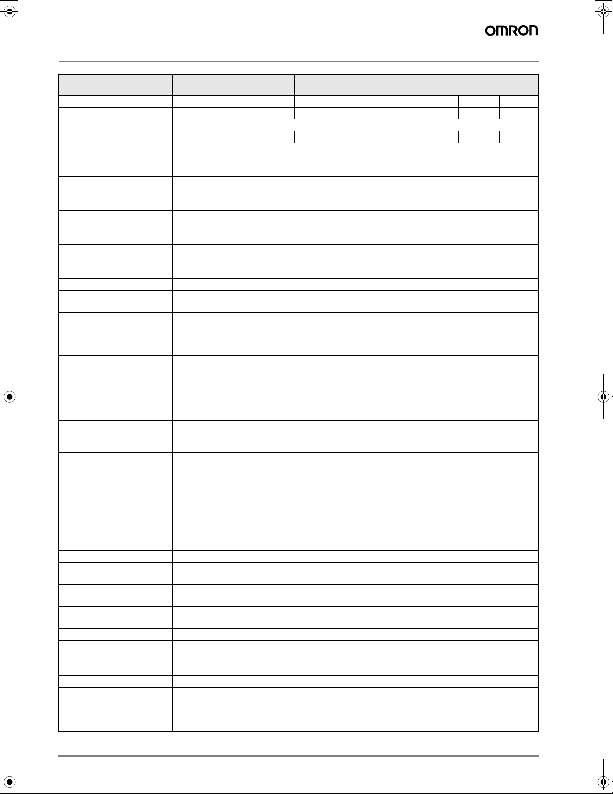
Rating and Performance
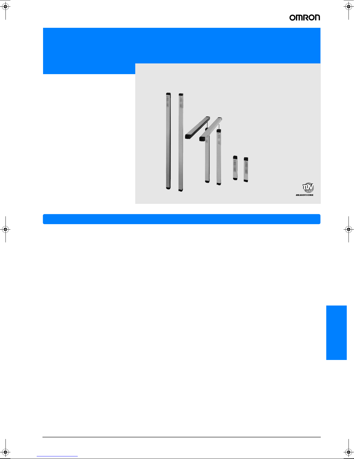
Type F3S-B
###
P*1
Stand-alone
F3S-BM
###
P
##
*1
Master unit for series connection
F3S-BS
###
*1
Slave unit for series connection
No. of optical axes 12 to 66 6 to 33 4 to 22 12 to 66 6 to 33 4 to 22 12 to 30 6 to 15 4 to10
Optical-axis pitch 25 mm 50 mm 75 mm 25 mm 50 mm 75 mm 25 mm 50 mm 75 mm
Optical resolution
(Detection capability)
Non-transparent: in diameter
30 mm 55 mm 80 mm 30 mm 55 mm 80 mm 30 mm 55 mm 80 mm
Protective height 300 / 450 / 600 / 750 / 900 / 1,050 / 1,200 / 1,350 / 1,500 /
1,650 mm
300 / 450 / 600 / 750 mm
Detection distance 0.3 to 5.0 m, up to 8 m on request
Response time ON to OFF: See table “Response Time”
OFF to ON*2: Default 100 ms (selectable with F39-U1E, 80 to 400 ms)
Startup waiting time 2 s max.
Supply voltage: Vs 24 VDC ± 20% (including 5 Vp-p ripple)
Current
consumption
400 mA max. (under no-load conditions)
Light source Infrared LED (880 nm wavelength). Lifetime: 50,000 hrs. at 25 °C.
Effective aperture angle Within ± 5° for the emitter and receiver at a detection distance of at least 3 m according to IEC
61496-2
Operating mode Light ON
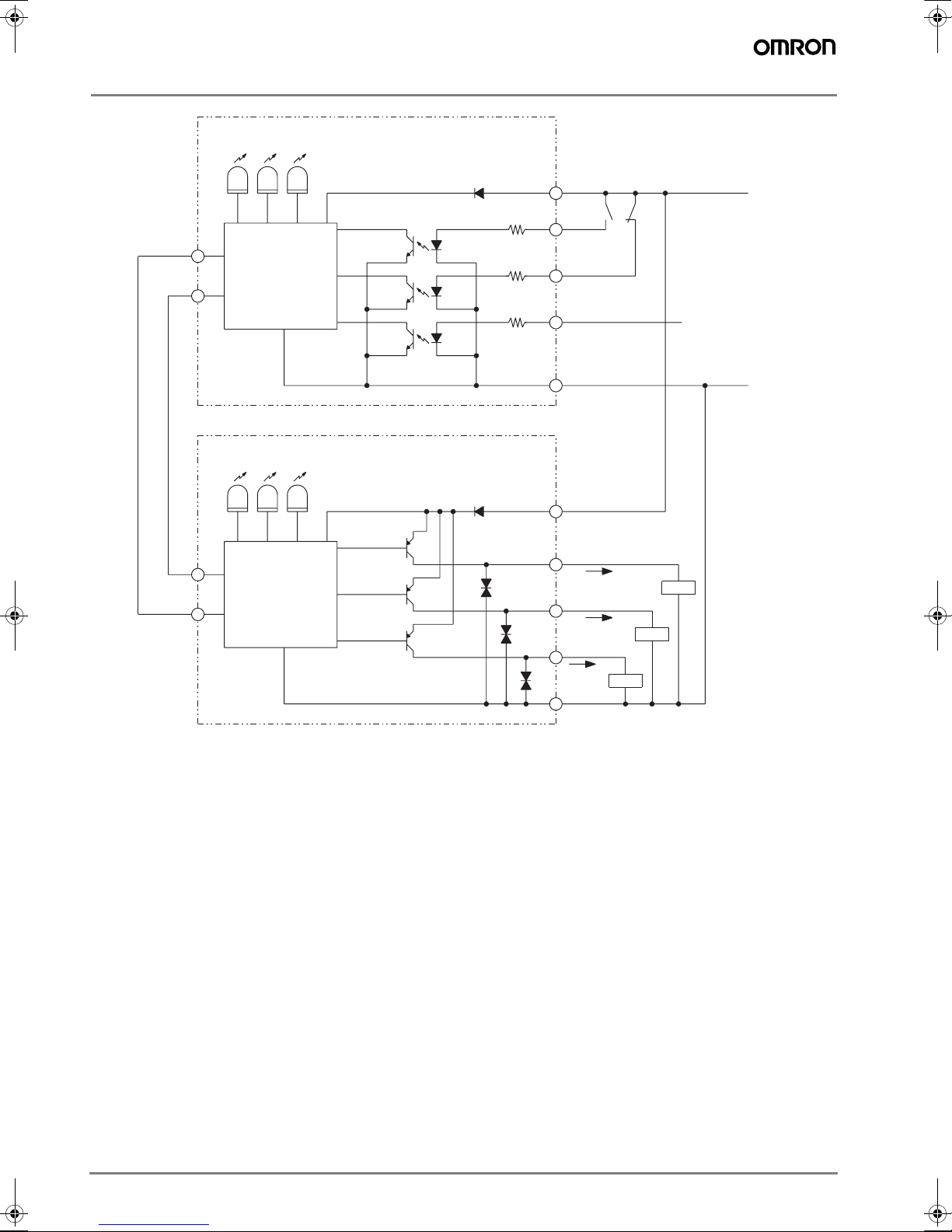
Control output Two PNP transistor outputs, load current 200 mA max., residual voltage 2 V max. (except for volt-
age drop due to cable extension)
Instability output PNP transistor output (not safety-related control output),
activated during an insufficient light detection, failure detection and connection with F39-E1,
load current 100 mA max., residual voltage 2 V max. (except for voltage drop due to cable exten-
sion)
Protection circuit Output short-circuit protection, power supply reverse connection protection
Start/restart
interlock function
Mode selection before power ON by connecting ”Interlock selection input” line to:
Active: No connection or 0 to 2.5 VDC, 3 mA max.
Inactive: Instability output line
Reset of start/restart interlock by connecting ”Interlock selection input” line to:
Interlock reset: 17 VDC to Vs, 20 mA max. Duration time 15 to 2,500 ms
External test function Mode selection by connecting ”External test input” line to:
Active: 17 VDC to Vs, 10 mA max. Duration time at least 15 ms
Inactive: No connection or 0 to 2.5 VDC, 2 mA max.
Relay monitoring
function (optional)
Default inactive, selectable with F39-U1E
Relay monitoring input line with NC contact connected,
Available level: 17 VDC to Vs, 10 mA max.
Allowed relay delay time*3: Selectable between 20 and 300 ms
Termination when not selected: No connection or 0 to 2.5 VDC, 2 mA max.
Start interlock function
(optional)
Default inactive, selectable with F39-U1E
Blanking function
(optional)
Default inactive, selectable with F39-U1E
Indicator See ”Indicators” No indicators
Connection method For Extension cable: 8 pins, M12 connector
For Series connection cable: 6 pins, M12 connector
Ambient temperature During operation: –10 to 55 °C (with no freezing)
During storage: –25 to 70 °C
Ambient humidity During operation: 35 to 85 %RH (with no condensation)
During storage: 35 to 95 %RH
Insulation resistance 20 MΩmin. (at 500 VDC)
Dielectric strength voltage 1,000 VAC 50/60 Hz for 1 min
Degree of protection IEC60529 IP65
Vibration resistance Normal operation: 10 to 55 Hz, double-amplitude: 0.7mm, X, Y and Z directions 20 sweeps
Shock resistance Normal operation: 100 m/s2[10 G], X, Y and Z directions: 1000 times
Materials Case: Aluminum
Front cover: PMMA (acrylic resin)
End caps: PA6
Size (cross section) 30 x 40 mm
F502-EN2-04.book Seite 34 Dienstag, 26. Juli 2005 5:48 17
G-35F3S-B
F3S-B
Note: 1 .For detailed type names and optical specifications, see „Type Naming Rule“
2 .Nominal value (set time). The accuracy is -0 ... +70% of the ON to OFF response time.
3 .Only with F3S-B
###
2P and BM
###
2P
##
.
4 .For the 1,050 mm protective height and longer types.
5 .Only with F3S-B
###
P
#
and BM
##
2P
##
.
Indicators
Accessories Test rod*3, mounting brackets (top and bottom), mounting brackets (intermediate)*4, mounting
plates*5, Instruction manual*5
Applicable standard IEC(EN)61496-1 TYPE 2 ESPE (Electro-Sensitive Protective Equipment)
IEC 61496-2 TYPE 2 AOPD (Active Opto-electronic Protective Devices)
Emitter IR-power indicator: Lit when emitting.
Interlock indicator: Lit during start/restart interlock or start interlock.
External test/ blanking indicator: Lit during external test. / Flashing when using blanking function.
Receiver ON-state indicator: Lit when receiving light.
OFF-state indicator: Lit with interrupted light.
Flashing during connection with F39-E1 or with failure.
Instability indicator: Lit with an insufficient light reception or failure.
Flashing during connection with F39-E1.
Type F3S-B
###
P*1
Stand-alone
F3S-BM
###
P
##
*1
Master unit for series connection
F3S-BS
###
*1
Slave unit for series connection
ON
OFF
UNSTAB
POWER
INTER-
LOCK
EXT.TEST
BLANKING
Instability indicator
External test /
blanking indicator
<Emitter Indicators> <Receiver Indicators>
(Green) (Orange)
Optical- axis
line mark
ON-state indicator
(Green)
IR-power indicator
(Orange)
Interlock indicator
(Yellow) OFF-state indicator
(Red)
F502-EN2-04.book Seite 35 Dienstag, 26. Juli 2005 5:48 17
G-36 Safety Sensors / Components
Table of Response Time
Stand-alone type
Series connection types
The following chart shows the response time of combinations of a master unit and a slave unit connected in series. For example,
the response time of the combination of F3S-BM122P30 and F3S-BS302 is 30 ms.
Response time [ms ] Response time [ms ] Response time [ms ]
F3S-B122P 20 F3S-B065P 20 F3S-B047P 20
F3S-B182P 20 F3S-B095P 20 F3S-B067P 20
F3S-B242P 20 F3S-B125P 20 F3S-B087P 20
F3S-B302P 23 F3S-B155P 20 F3S-B107P 20
F3S-B362P 27 F3S-B185P 20 F3S-B127P 20
F3S-B422P 30 F3S-B215P 21 F3S-B147P 20
F3S-B482P 34 F3S-B245P 22 F3S-B167P 20
F3S-B542P 37 F3S-B275P 24 F3S-B187P 20
F3S-B602P 41 F3S-B305P 26 F3S-B207P 20
F3S-B662P 45 F3S-B335P 28 F3S-B227P 21
Response time [ms]
Slave unit F3S-
Master unit
BS122 BS182 BS242 BS302
F3S-BM122P
##
20 23 27 30
F3S-BM182P
##
23 27 30 34
F3S-BM242P
##
27 30 34 37
F3S-BM302P
##
30 34 37 41
F3S-BM362P
##
34 37 41 45
F3S-BM422P
##
37 41 45 49
F3S-BM482P
##
41 45 49 54
F3S-BM542P
##
45 49 54 57
F3S-BM602P
##
49 54 57 61
F3S-BM662P
##
54 57 61 65
Response time [ms]
Slave unit F3S-
Master unit
BS065 BS095 BS125 BS155
F3S-BM065P
##
20 20 20 21
F3S-BM095P
##
20 20 21 22
F3S-BM125P
##
20 21 22 24
F3S-BM155P
##
21 22 24 26
F3S-BM185P
##
22 24 26 28
F3S-BM215P
##
24 26 28 30
F3S-BM245P
##
26 28 30 32
F3S-BM275P
##
28 30 32 34
F3S-BM305P
##
30 32 34 35
F3S-BM335P
##
32 34 35 37
Response time [ms]
Slave unit F3S-
Master unit
BS047 BS067 BS087 BS107
F3S-BM047P
##
20 20 20 20
F3S-BM067P
##
20 20 20 20
F3S-BM087P
##
20 20 20 20
F3S-BM107P
##
20 20 20 20
F3S-BM127P
##
20 20 20 21
F3S-BM147P
##
20 20 21 23
F3S-BM167P
##
20 21 23 24
F3S-BM187P
##
21 23 24 25
F3S-BM207P
##
23 24 25 26
F3S-BM227P
##
24 25 26 27
F502-EN2-04.book Seite 36 Dienstag, 26. Juli 2005 5:48 17
F3S-B
G-37F3S-B
Characteristic data
Operating Range
F3S-B122P
Parapendicular to Center Line of Lenses Parallel to Center Line of Lenses
F3S-B662P
Parapendicular to Center Line of Lenses Parallel to Center Line of Lenses
Distance Y (mm)
Distance X (m)
-300
-200
-100
0
100
200
300
0 2 4 6 8
Y
X
Distance X (m)
-300
-200
-100
0
100
200
300
0 2 4 6 8
Y
X
Distance Y (mm)
Distance Y (mm)
Distance X (m)
-300
-200
-100
0
100
200
300
0 2 4 6 8
Y
X
Distance X (m)
Distance Y (mm)
-300
-200
-100
0
100
200
300
0 2 4 6 8
Y
X
F502-EN2-04.book Seite 37 Dienstag, 26. Juli 2005 5:48 17
G-38 Safety Sensors / Components
I/O Circuit Diagram
IR-light
indicator
2
3
1
4
7
OFF-state
indicator
ON-state
indicator
2
7
Instability
indicator
3
1
4
5
6
6
5
Green
Brown
White
Yellow
Blue
Brown
Green
White
Yellow
Pink
Grey
Pink
Grey
+24 V
0 V
Load
Load
Load
Instability
Blue
output
RS-485(A)
RS-485(B)
Interlock
indicator Ext. test/blanking
indicator
External test
input
Interlock selection
input
Relay monitoring
input
Main emitter
circuit
Main receiver
circuit
Control output 1
Control output 2
F502-EN2-04.book Seite 38 Dienstag, 26. Juli 2005 5:48 17
F3S-B
G-39F3S-B
Dimensions
Safety Light Curtain
F3S-B
Note:All units are in Millimeters unless otherwise indicated.
Accessoires
Type A
Protective
height
B
Full length
F3S-B122, -B065, -B047 300 343
F3S-B182, -B095, -B067 450 493
F3S-B242, -B125, -B087 600 643
F3S-B302, -B155, -B107 750 793
F3S-B362, -B185, -B127 900 943
F3S-B422, -B215, -B147 1050 1093
F3S-B482, -B245, -B167 1200 1243
F3S-B542, -B275, -B187 1350 1393
F3S-B602, -B305, -B207 1500 1543
F3S-B662, -B335, -B227 1650 1693
Mounting Bracket (Top and Bottom) Mounting Plate
Only supplied with types which have a protective height of 1050 mm or longer (Including inter-
mediate brackets). Only needed for rear mounting
M12 connector
Master unit
M12 connector
A (Protective height)
B
40.3
3
34
10.5
30
3
9.5
36
R1.75
20
5.5
R2.75
R4.5
Ø 25.5
3.5
20˚
35˚
46
2
22 16 12
30
42.74
36.5
20
7
5
12
5.5 R2.75
6.25
3
22.5 28.74
4
F502-EN2-04.book Seite 39 Dienstag, 26. Juli 2005 5:48 17
G-40 Safety Sensors / Components
Options (Order Separately)
Extension Cable
(Set of 2: Emitter > gray, Receiver > black)
F39-JB1A (L = 3 m)
F39-JB2A (L = 7 m)
F39-JB3A (L = 10 m)
Series Connection Cable
(Set of 2: Emitter > gray, Receiver > black)
F39-JB1B
Optional Function Kit
F39-EU1E
Intermediate Mounting Bracket
Only needed for types which have a protective height of 1050 mm or longer
L-shaped intermediate bracket
Fixing screw for bracket (M4x10)
U-shaped intermediate bracket
Mounting screw for sensor (M6x8)
Flat intermediate bracket
Rubber
42 L
M12 Round vinyl-insulated cord
5.7 mm dia. (32/0.1 mm dia.) 8 cores
Unit: mm
Ø 15
M12
48.5 300
Unit: mm
Ø 15
This set includes the following items:
· F39-U1E OptionalFunction Software
· F39-E1 Interface Unit
· F39-JB1C Interface Cable
The F39-U1E Optional Function Software is the WINDOWS®
-based software for use with the F39-E1 Interface Unit to pro-
gram the F3S-B Safety Light Curtain, and provided with one
3.5 inch floppy disk. This software has the following features:
· Set the following functions to the F3S-B
- Start interlock function
- Relay monitoring function
- Blanking function
·
Display each axis and each input line condition of the F3S-B
· Change the ON delay time
Note: The F3S-B is not in normal operation during connection with the F39-E1.
The control outputs are held in their OFF-state. For detailed information
please refer to “Details of F39-EU1E” in this data sheet.
!WARNING
After setting the blanking function, check that the F3S-B detects a test
rod at any position in the F3S-B detection zone through which a per-
son reaches the hazardous part of the machine. If any positions are
found by check above, install protective structures to there to prevent
intrusion which F3S-B can not detect. Failure to do so may result in
serious injury.
Perform the installation check and the periodical inspection described
in the F3S-B manual.
Disconnect the outputs of the F3S-B from the load when program-
ming it using the F39-U1E software and with F39-E1 interface unit.
Failure to do so may result in serious injury.
Do not connect the F39-E1 to a power supply with a voltage higher than
24 VDC +20 %. Do not connect the F39-E1 to an AC power supply.
F502-EN2-04.book Seite 40 Dienstag, 26. Juli 2005 5:48 17