Onatco Super-Efficiency SE-199-80 User manual

Recognize this symbol as an indication of
important Safety Information!
Do Not Destroy this Manual. Please read carefully
and keep in a safe place for Future Reference.
NO
TICE
This water heater is designed for use in a commercial application. The installation and maintenance of it
should be performed by qualified, licensed service personnel.
W
ARNING
Read and review this entire manual with special emphasis on the Venting and Operation Sections prior to
any installation work.
CALIFORNIA PROPOSITION
65
W
ARNING
This product contains chemicals known to the State of California to cause cancer, birth defects and other
reproductive harm.
W
ARNING
If the information in these instructions are not followed exactly, a fire or explosion may result causing
property damage, personal injury or death.
FOR YOUR SAFETY!
— Do not store or use gasoline or other flammable
vapors or liquids or other combustible materials in
the vicinity of this or any other appliance. To do so
may result in an explosion or fire
— WHAT TO DO IF YOU SMELL GAS
•
Do not try to light any appliance.
•
Do not touch any electrical switch; do not use any
phone in your building.
•
Immediatelycallyourgassupplierfromaneighbor’s
phone. Follow the gas supplier’s instructions.
•
If you cannot reach your gas supplier, call the fire
department.
•
Do not return to your building until authorized by
the gas supplier or fire department.
— Improper installation, adjustment, alteration, service
or maintenance can cause injury, property damage
or death. Refer to this manual. Installation and
service must be performed by a qualified installer,
service agency or gas supplier.
Printed in the USA 1 AP15135 (5/09)
Installation,OperationManual,andServiceManualforSuper‐E
SP(Spark)High‐EfficiencyWaterHeaterModels:
SE‐199‐80
SE‐199‐119
NationalCombustionCo.,Inc.
104‐11180thStreet
Jamaica,NY11433
Ph:718‐291‐8400Fx:718‐291‐6870
www.nationalcombustion.com

DIMENSIONAL INFORMATION
All dimensions shown in English and Metric
MODEL
NUMBER UNITS HEIGHT WIDTH DEPTH VENT
W
A
TER CONNECTIONS APPROX
SHIPPING WT.
INLET OUTLET
HE80-199 inches 72 23 1/2 32 3* 1-1/2 1-1/2 235 lbs.
mm 1854 597 813 76 38 38 106 kgs
HE119-199 inches 73 27 36 3* 1-1/2 1-1/2 405 lbs.
mm 1854 686 914 76 38 38 184 kgs
SPECIFICATIONS
RECOVERY CAPACITIES
Recovery in U.S. Gallons/Hr. (GPH) and Liters/Hr. (LPH) at Various Temperature Rises
MODEL
NUMBER INPUT (BTU/HR)
NAT. & LP THERMAL
EFFICIENCY UNITS 40°F
(22.2°C) 50°F
(27.8°C) 60°F
(33.3°C) 70°F
(38.9°C) 80°F
(44.4°C) 90°F
(50.0°C) 100°F
(55.6°C) 110°F
(61.1°C) 120°F
(66.7°C)
SE199-80
SE199-119 199,000 95% GPH 573 458 382 327 286 255 229 208 191
LPH 2169 1735 1446 1239 1084 964 867 789 723
Recovery rating is based on thermal efficiencies obtained in Intertek testing laboratory.
All models exceed the minimum energy efficiency requirements of current ASHRAE 90.1 requirements.
MAXIMUM DELIVERY
In U.S. Gallons and Liters (Includes useable storage and recovery for indicated times)
MODEL
NUMBER GALLONS/
LITERS MAX
SETPOINT INPUT (BTU/HR)
NAT. & LP TEMP.
RISE UNITS 5
MIN. 10
MIN. 15
MIN. 20
MIN. 30
MIN. 45
MIN. 1
HR. 2
HR. 3
HR. MIN. TO RECOVER
CONTENTS
SE199-80 80
303 160º
71ºC 199,000 100°F GAL. 75 94 113 132 171 228 285 514 743 21
37.7°C LTR. 284 357 429 501 646 863 1079 1947 2814
SE199-119 119
450 160º
71ºC 199,000 100°F GAL. 102 121 141 160 198 255 312 542 771 31
37.7°C LTR. 338 460 532 604 749 966 1183 2050 2918
All models have a maximum setpoint of 160°F with the exception of the HE55-160 and HE55-199 booster models. The HE55-160 and HE55-199 have a maximum setpoint of 180°F.
* NOTE: The 180º F models are shipped with all necessary components for an approved installation (see Booster Installation Kit for component list on Page 7.)
0" CLEARANCE
TO
COMBUSTIBLES ON ALL
SUPER-E SP
UNITS, HOWEVER, A 24"
(61 cm) CONTROL PANEL
SERVICE CLEARANCE IS
RECOMMENDED.
All models require a 120V power source.

TABLE OF CONTENTS ______________________
Part1:GeneralSafetyPrecautions ___________________________________4-5
Part2: Installation _______________________________________________6-10
Local Installation Regulations ____________________________________ 6
Location_____________________________________________________ 6
Temperature and Pressure Relief Valve ____________________________ 6
Expansion Tank_______________________________________________ 6
Potable Water Connections______________________________________ 7
Lighting and Operating Instructions________________________________ 8
Electrical Connection___________________________________________ 9
Gas Connection_____________________________________________9-10
Part3:Venting,CombustionAir&Condensate Removal ________________11-17
General ____________________________________________________ 11
Approved Materials for Exhaust Vent and Intake Air__________________ 11
Exhaust Vent and Intake Air Vent Pipe Locations_________________ 11-13
Exhaust Vent and Intake Air Vent Sizing___________________________ 14
Longer Vent Runs ____________________________________________ 14
Exhaust Vent and Intake Air Pipe Installation ____________________ 14-15
VeryImportant Set-up Instructions________________________________ 15
Concentric Vent______________________________________________ 16
Vent Length Maximum Reference Chart ___________________________ 17
Part4:Operation ______________________________________________18-20
Overall Appliance and Control Operation __________________________ 18
Status Mode_________________________________________________ 18
Test Mode _______________________________________________ 18-19
Operating Instructions _________________________________________ 20
Shutdown Procedure__________________________________________ 20
Prevent Combustion Air Contamination____________________________ 20
Corrosive Contaminants and Source Products to Avoid _______________ 21
Condensate _________________________________________________ 21
Part5 :ComponentsandWiring ___________________________________22-23
Components Diagram _________________________________________ 22
Wiring Diagram ______________________________________________ 23
Part6:Troubleshooting _________________________________________24-25
Part7:Howto Get YourSuper-EServiced _____________________________ 26
Part8:StandardPipingDiagrams ___________________________________ 27
1 Unit, Standard______________________________________________ 27
2 Units without Recirculator_____________________________________ 28
2 Units with Recirculator _______________________________________ 29
Part9: Warranty _________________________________________________ 30
3

D A N G E
R
F
L
A
MM
A
B
L
E
S
Flammable
V
a
p
o
r
s
V
a
p
o
r
s
f
r
o
m
flammable
W
a
t
e
r
h
e
a
t
e
r
h
a
s
a
m
a
i
n
li
qu
i
d
s
will
e
x
p
l
o
d
e
and
bu
r
n
e
r
and
pilot flame.
c
a
t
c
h
f
i
r
e
c
a
u
s
i
n
g
death
o
r
T
h
e
pilot flame:
s
e
v
e
r
e
bu
r
n
s
.
1.
whichcan come on
at
Do not
use
o
r
s
t
o
r
e
flammable
any
time
and
p
r
o
du
c
t
s
s
u
c
h
as
g
a
s
o
li
n
e
,
2. will
ignite flammable
s
o
l
v
e
n
t
s
o
r
a
dh
e
s
i
v
e
s
in
the
va
p
o
r
s
.
s
a
m
e
r
oo
m
o
r
a
r
e
a
n
e
a
r
the
V
a
p
o
r
s
:
w
a
t
e
r
h
e
a
t
e
r
.
1.
cannot be
seen,
K
ee
p
flammable p
r
o
du
c
t
s
:
2.
a
r
e
h
e
av
i
e
r
than air,
1. far away
f
r
o
m
h
e
a
t
e
r
,
3.
go
a
long
way
on the
f
l
oo
r
and
2. in
a
pp
r
o
v
e
d
c
o
n
t
a
i
n
e
r
s
,
4.
can be
c
a
rr
i
e
d
f
r
o
m
3.
tightly
c
l
o
s
e
d
and
o
t
h
e
r
r
oo
m
s
to the pilot
4.
out of
c
h
il
d
r
e
n
'
s
r
e
a
c
h
.
flame
by air
c
u
rr
e
n
t
s
.
I
n
s
t
a
ll
a
t
i
o
n
:
a
r
e
at
l
e
a
s
t
18"
above the
Do not
i
n
s
t
a
ll
w
a
t
e
r
h
e
a
t
e
r
f
l
oo
r
.
T
h
i
s
will
r
e
du
ce
,
but
not
w
h
e
r
e
flammable p
r
o
du
c
t
s
will
eliminate,the
r
i
s
k
of
va
p
o
r
s
be
s
t
o
r
e
d
o
r
u
s
e
d
un
l
e
ss
the
being ignited
by
the
main
main
bu
r
n
e
r
and
pilot
f
l
a
m
e
s
bu
r
n
e
r
o
r
pilot flame.
Read
and
follow
w
a
t
e
r
h
e
a
t
e
r
w
a
r
n
i
n
g
s
and
i
n
s
t
r
u
c
t
i
o
n
s
.
I
f
o
w
n
e
r
s
manual
i
s
m
i
ss
i
n
g
,
c
o
n
t
a
c
t
the
r
e
t
a
il
e
r
o
r
m
a
nu
f
a
c
t
u
r
e
r
.
PART 1: GENERAL SAFETY PRECAUTIONS
Be sure to read and understand the entire Use & Care Manual before attempting to install or operate this water heater.
Pay particular attention to the following General Safety Precautions. Failure to follow these warnings could result in a fire
or explosion, causing property damage, bodily injury or death. Should you have any problems understanding the instruc-
tions in this manual, STOP, and get help from a qualified installer or service technician or the gas supplier.
W
ARNING
Gasoline, as well as other flammable materials and
liquids (adhesives, solvents, etc.), and the vapors
they produce, are extremely dangerous. DO NOT
handle, use or store gasoline or other flammable
or combustible materials anywhere near or in the
vicinity of a water heater. Be sure to read and follow
the warning label pictured below and other labels on
the water heater, as well as the warnings printed in
this manual. Failure to do so can result in property
damage, bodily injury, or death.
D
ANGER
Failure to install and properly vent the water heater
to the outdoors as outlined in the Venting Section
of this manual can result in unsafe operation of the
water heater. To avoid the risk of fire, explosion, or
asphyxiation from carbon monoxide, never operate
this water heater unless it is properly vented and has
an adequate air supply for proper operation. Be sure
to inspect the vent system for proper installation at
initial start-up and at least annually thereafter. Refer
to maintenance section of this manual for more
information regarding vent system inspections.
D
ANGER
LIQUEFIED PETROLEUM MODELS
-Propane, or LPgas, must be used with greatcaution.
· It is heavier than air and will collect first in lower
areas making it hard to detect at nose level.
· Make sure to look and smell for LP leaks before
attempting to light appliance. Use a soapy solution
to check all gas fittings and connections. Bubbling at
a connection indicates a leak that must be corrected.
When smelling to detect an LP leak, be sure to sniff
near the floor.
· Gas detectors are recommended in LP applications
and their installation should be in accordance with
the manufacturer’s recommendations and/or local
laws, rules, regulations or customs.
· It is recommended that more than one method be
used to detect leaks in LP applications.
IF LP GAS IS PRESENT OR SUSPECTED:
· DO NOT attempt to find the cause yourself;
· DO NOT try to light any appliance;
· DO NOT touch any electrical switch;
· DO NOT use any phone in your building.
· Leave the house immediately and make sure your
family and pets leave also.
· Leave the doors open for ventilation and contact
the gas supplier, a qualified service agency or the
fire department.
· Keep the area clear until the service call has been
made, the leak is corrected, and a qualified agency
has determined the area to be safe.
W
ARNING
Both LP and natural gas have an odorant added to
help detection. Some people may not physically be
able to smell or recognize this odorant. If unsure
or unfamiliar about the smell associated with LP or
natural gas, ask the gas supplier. Other conditions,
such as “Odorant Fade”, which causes the odorant
to “fade”, or diminish in intensity can also hide or
camouflage a gas leak.
D
ANGER
Water heaters utilizing Liquefied Petroleum gas (LP)
are different from natural gas models. A natural gas
heater will not function safely on LP gas and vice
versa. No attempt should ever be made to convert a
heater from natural gas to LP gas. To avoid possible
equipment damage, personal injury or fire: DO
NOT connect this water heater to a fuel type not in
accordance with unit rating plate. Propane gas for
propane units. Natural gas for natural gas units.
These units are not certified for any other type fuel.
4

Temperature Time to Produce Serious Burn
120°F (49°C) More than 5 minutes
125°F (52°C) 1½ to 2 minutes
130°F (54°C) About 30 seconds
135°F (57°C) About 10 seconds
140°F (60°C) Less than 5 seconds
145°F (63°C) Less than 3 seconds
150°F (66°C) About 1½ seconds
155°F (68°C) About 1 second
PART 1: GENERAL SAFETY PRECAUTIONS cont’d
WARNING
LP appliances should not be installed below-grade
(for example, in a basement) if such installation is
prohibited by federal, state and/or local laws, rules,
regulations, or customs.
To meet commercial water use needs, the thermo-
stat on this water heater is adjustable up to 160°F
(71°C).However,watertemperaturesover
125°F (52°C) can cause severe burns instantly or
death from scalds. This is the preferred starting
point for setting the controls for supplying gen-
eral purpose hot water.
Safety and energy conservation are factors to be
considered when setting the water temperature
on the thermostat. The most energy efficient
operation will result when the temperature setting
is the lowest that satisfies the needs consistent
with the application.
Maximum water temperatures occur just after burner has
shut off. To find temperature of the water being deliv-
ered, turn on a hot water faucet and place a thermome-
ter in the hot water stream and read the thermometer.
The following chart details the relationship of water tem-
perature and time with regard to scald injury and may be
used as a guide in determining the safest water temper-
ature for your applications.
TIME / TEMPERATURE RELATIONSHIPS IN SCALDS
Table courtesy of Shrines Burn
Institute
The temperature of the water in the heater can be regu-
lated by setting the temperature on the electronic ther-
mostat. To comply with safety regulations, the thermostat
was set at its lowest setting before the water heater was
shipped from the factory. See the section titled SET
POINT ADJUSTMENT PROCEDURE to set the electron-
ic thermostat.
D
ANGER
There is a Hot Water SCALD Potential if the
thermostat is set too high.
NOTE: When this water heater is supplying
general purpose hot water requirements for use by
individuals, a thermostatically controlled mixing
valve for reducing point of use water temperatures
is recommended to reduce the risk of scald injury.
Contact a licensed plumber or the local plumbing
authority for further information.
5

PART 2: INSTALLATION
W
ARNING
Read and review this entire manual with special
emphasis on the Venting Sections and Operation
Sections prior to any installation work.
A. LOCAL INSTALLATION REGULATIONS
This water heater must be installed in accordance with
these instructions, local codes, utility company require-
ments, and/or in the absence of local codes, the latest
edition of the National Fuel Gas Code ANSI 223.1 in the
United States or CAN/CSA B149.1 installation code in
Canada.
The water heater must be located or protected so it is
not subject to physical damage, for example, by moving
objects, area flooding, etc.
CA
UTION
The water heater should not be located in an area
where leakage of the tank or connections will result in
damage to the area adjacent to it or to lower floors of
the structure. When such areas cannot be avoided, it
is recommended that a suitable catch pan, adequately
drained, be installed under the water heater.
NOTE: Auxiliary catch pan installation MUST con-
form to the applicable local codes
B. LOCATION
Choose a location for your water heater centralized to
the piping system, along with consideration to vent pipe
length. As the length of vent pipe increases, the firing
rate of the appliance decreases. You must also locate
the Super-E SP where it will not be exposed to below
freezing temperatures. Additionally, you will need to
place the water heater so that the controls, drain, inlet/
outlet, and gas valve are easily accessed. This appliance
must not be installed outdoors, as it is certified as an
indoor appliance, and must be kept vertical and on a
level surface. Also, care must be exercised when
choosing the location of this appliance where leakage
from the relief valve, leakage from related piping, or leak-
age from the tank or connections, will not result in dam-
age to the surrounding areas or to the lower floors of the
building. A water heater should always be located in
an area with a floor drain or installed in an adequate-
ly drained catch pan suitable for water heaters.
Proper clearance must be provided around the
Super-E SP as follows: Sides, bottom, top, and back
are 0" (zero clearance). Front of the appliance needs 24"
(61cm) service clearance minimum. This front service
may be achieved by a non-rated or combustible door or
access panel; providing the 24" (61cm) service clearance
is achieved when the door is opened or panel is
removed. This water heater must not be located near
flammable liquids such as gasoline, adhesives,
solvents, paint thinners, butane, liquefied propane,
etc. as the controls of this appliance could ignite
those vapors, causing an explosion.
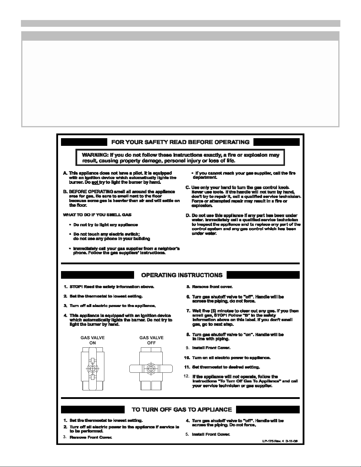
C. TEMPERATUREAND PRESSURERELIEF VALVE
A new combination temperature and pressure relief valve,
complying with the Standard for Relief Valves and
Automatic Gas Shutoff Devices for Hot Water Supply
Systems, ANSI Z21.22 or Standard CSA 4.4, must be
installed in the opening provided on the water heater at
the time of installation. No valve is to be placed between
the relief valve and the water heater. For circulating tank
installation, the separate storage tank(s) must have
similar protection. The pressure rating of the relief valve
must not exceed the maximum working pressure as
marked on the front of the water heater. The Btu/h rating
of the relief valve must equal or exceed the Btu/h input of
the water heater as noted on its rating plate. Connect the
outlet of the relief valve to a suitable open drain. The
discharge line must pitch downward from the valve to
allow complete draining (by gravity) of the relief valve and
discharge line, and must be no smaller than the outlet of
the relief valve. The end of the discharge line should not
be threaded or concealed and should be protected from
freezing. No valve of any type, restriction or reducer
coupling should be installed in the discharge line. In the
U.S., local codes shall govern the installation of relief
valves. In Canada, use CAN/CSAB149.1.
D. EXPANSION TANK
A potable hot water expansion tank may be required to
offset the water expansion as the water is heated. In
most city plumbing systems, the water meter has a no
return or back flow device built into the system to prevent
back flowing of water back into city mains. Back flow pre-
venters may be found on all incoming water supplies.
Under these circumstances, you will need a hot water
expansion tank listed for potable water use. The expan-
sion tank should be located on the cold inlet piping close
to the water heater. The expansion tank must be suit-
able for hot potable water.
WARNING
The manufacturer’s warranty does not cover any
damage or defect caused by installation or attach-
ment or use of any special attachments such as ener-
gy saving devices (other than those authorized by the
manufacturer) into, onto, or in conjunction with the
waterheater.Theuseof suchunauthorizeddevicesmay
shorten the life of the water heater and may endanger
life and property. The manufacturer disclaims any
responsibility for such loss or injury resulting from
the use of such unauthorized devices.
6

E. DOMESTIC WATER CONNECTIONS
The water connections must be installed in accor-
dance with all national and local plumbing codes, or
any prevailing standard. NEVER USE DIELECTRIC
UNIONS OR GALVANIZED STEEL FITTINGS ON
SUPER-E SP CONNECTIONS. The inlet and out- let
connections are 1" on the 55 gallon models and 1-
1/2" on the 80 and 119 gallon models. On the cold inlet,
install a 1" brass tee on the 55 gallon models, or a 1-1/2"
brass tee on the 80 and 119 gallon models. On the run
of the 1" brass tee install, with pipe sealant, compound a
1" brass drain cock or it’s equivalent (not supplied). Into
the branch of the 1" or 1-1/2" brass tee install a copper
male adapter to match with the copper plumbing system.
For convenience, you may install a shut off valve and a
union in the cold inlet piping to ease servicing in the fu-
ture. Ifthereisabackflowpreventer,oranytypeofa check
valveinthesystem,thenyoumustinstallanaddi- tional tee for
asuitablepotablethermalexpansiontank. (See section on
Expansion Tank.) In the hot outlet con- nection, (top
left), install a suitable adapter to match the copper
tubing of the plumbing system. A thermal trap or heat
trap loop may be installed here to provide additional
energy savings and prevent thermal siphoning of domes-
tic hot water. If required, a domestic hot water temper-
ing/anti-scald valve should be installed into the hot water
line to prevent the maximum outlet water temperature
from exceeding 125°F (52°C) to prevent scald injury.
7

G. LIGHTING AND OPERATING INSTRUCTIONS
W
ARNING
If the information in this manual is not followed
exactly, a fire or explosion may result causing
property damage, personal injury or loss of life.
Do not store or use gasoline or other flammable
vapors and liquids in the vicinity of this or any other
appliance.
WHAT TO DO IF YOU SMELL GAS
• Do not try to light any appliance.
• Do not touch any electrical switch: do not
use any phone in your building.
• Immediately call your gas supplier from a
neighbor’s phone. Follow the gas
supplier’s instructions.
• If you cannot reach your gas supplier,
call the fire department. Installation and
service must be performed by a qualified
installer, service agency or the gas
supplier.
8

3/4
.824
278
190
152
130
115
105
1
1.049
520
350
285
245
215
195
1 1/4
1.380
1,050
730
590
500
440
400
1 1/2
1.610
1,600
1,100
890
760
670
610
3/4
.824
90
84
79
72
64
1
1.049
170
160
150
130
120
1 1/4
1.380
350
320
305
275
250
1 1/2
1.610
530
490
460
410
380
}
225
210
}
W
ARNING
Tank MUST be full of water before power is turned
on. Heat exchanger coil WILL BE DAMAGED if ener-
gized even for a short time while the tank is dry. The
water heater’s warranty does not cover damage or
failure resulting from operation with an empty or par-
tially empty tank. (Reference is made to the limited
warranty for complete terms and conditions)
H. ELECTRICAL CONNECTION
The electrical connection for the Super-E SP is on the left
side of the combustion shroud. There is a 1/2" knock- out
location for electrical connection. All electrical wiring
must be performed by a qualified licensed electrician,
and in accordance with National Electrical Code and
Canadian Electrical Code, or to the applicable local
codes and standards. The electrical requirements are
for standard 120 volts, 60 Hz., 10 amp service. It is
recommended that an electrical disconnect switch be
placed near the water heater, and that the connection to
the Super-E SP be made using 3/8" extra-flex, or 3/8"
greenfield (or equivalent). This unit must be wired with
#14 AWG, and fused for no more than 15 amps. Itis
of extreme importance that this unit be properly
grounded and be connected with proper polarity!
Ground the water heater by connecting the green wire in
the electrical access compartment directly to the main
building ground system. It is very important that the
building system ground is inspected by a qualified
electrician prior to making this connection. Once all
connections have been made, the electrical access may
be closed. It is very important that the electrical power is
not turned on until gas and venting connections are
completed and the tank is full of water.
I. GAS CONNECTION
Refer to the below table to size the supply piping to
minimize pressure drop between meter or regulator
and unit. In Canada, use table found in CAN/CSA
B149.1
Maximum Capacity of Pipe in Cubic Feet of Gas per
Hour for Gas Pressures of 0.5 psi or Less and a
Pressure Drop of 0.3 Inch water Column
Gas Table
(Nominal
Iron Pipe Internal
Length of Pipe (Feet)
Size
Diameter
(inches)
(inches)
10
20
30
40
50
60
70
96
BTU’S
180
PER
370
HOUR
560
x1,000
(Nominal
Iron Pipe Internal
Length of Pipe (Feet)
Size
Diameter
(inches)
(inches)
80
90 100
125
150 175
200
59
55
BTU’S
110
100
PER
HOUR
It is recommended that a soapy solution be used to detect
leaks. Bubbles will appear on the pipe to indicate a leak is
present. The gas piping must be sized for the proper flow
and length of pipe, to avoid excessive pressure drop. Both
the gas meter and the gas regulator must be properly
sized for the total gas load. If you experience a pressure
drop greater than 1” WC, the meter, regulator or gas
line is undersized or in need of service. You can attach
a manometer to the incoming gas drip leg, by removing
the cap and installing the manometer. The gas pressure
must remain between 3.5” WC and 14” WC during stand-
by (static) mode and while in operating (dynamic) mode
at full output. If an in-line regulator is used, it must be
a minimum of 10 feet from the Super-E SP. It is
very important that the gas line is properly purged by
the installer, gas supplier or utility. Failure to properly
purge the lines or improper line sizing, will result in
ignition failure. This problem is especially noticeable in
NEW LP installations and also in empty tank situations.
This can also occur when a utility company shuts off
service to an area to provide maintenance to their lines.
The gas valve must not be replaced with a conventional
gas valve under any circumstances. As an additional
safety feature in the Super-E SP water heater, the gas
valve in this appliance has a flanged connection to the
swirl plate and blower.
Gas supply shall not exceed a maximum inlet pressure
of 14" water column (350 mm), 1/2 pound pressure (3.4
kPa), between 3.5” WC and 14” WC (natural and
propane). The entire piping system, gas meter, and reg-
ulator must be sized properly to prevent a pressure drop
greater than 0.5" of water column as stated in the
National Fuel Gas Code. Gas pressure information is
listed on the rating plate. It is very important that you
are connected only to the type of gas noted on the
rating plate; “LP” or propane gas or “Nat” natural
gas. All gas connections must be approved by the local
gas supplier or utility in addition to the governing
authority prior to turning the gas supply on. The nipple
provided for the inlet gas connection is 1/2", and it is
mandatory that a 3/4" to 1/2" reducing bushing (provided)
is used, threaded into the branch of a 3/4" tee, and a drip
leg fabricated, as per the National Fuel Gas Code and in
Canada refer to CAN/CSAB149.1.
You must ensure that the entire gas line to the reduc-
ing bushing connection at the Super-E SP is no
smaller than 3/4".
CAUTION
THE USE OF FLEXIBLE GAS CONNECTORS IS
NOT RECOMMENDED. HOWEVER, IF USED, IT IS
IMPERATIVE THAT THEY ARE SIZED
CORRECTLY.
FLEXIBLE
GAS
CONNECTORS
MUSTHAVEAMINIMUM
IDOF3/4".A
MINIMUM
3/4"IDMUSTBE
MAINTAINED
TO
AVOID
RESTRICTION
OF GASFLOW!NEVERREDUCE
THE GAS SUPPLYLINE BELOW 3/4"! In Canada, refer
to CAN/CSAB149.1for approvedconnections.
350
320
x1,000
9

Once all the inspections have been performed, the piping
system must be leak tested. If the leak test pressure is
higher than the maximum permissible inlet pressure, you
must isolate the Super-E SP from the gas line before
testing. In order to do this, you must disconnect the
union and cap the inlet gas line. In the event the gas
valve is exposed to a pressure greater than 1/2 PSI, 14"
water column, the gas valve must be replaced.
Failure to follow all precautions could result in fire,
explosion or death! It is recommended that a soapy
solution be used to detect leaks. Bubbles will appear and
indicate a leak is present. The gas piping must be sized
for the proper flow and length of pipe to avoid unaccept-
able pressure drop. Both the gas meter and the gas reg-
ulator must be properly sized for the total gas load. If you
experience a pressure drop greater than 1" W.C., the
meter or regulator or gas line may be undersized or in
need of service. On the inlet side of the gas valve, there
is a 1/8" NPT plug. This plug can be removed to attach a
manometer. You can attach a meter to the incoming gas
drip leg by removing the cap and installing the meter. The
gas pressure must remain between 3.5" and 14" of water
column during stand-by and unit running heat cycle. If
anin-lineregulator isused,itmustbeaminimumof 10 feet
fromtheSuper-E SP. It is very important that the gas
line is properly purged by the installer, gas supplier
or utility. Failure to properly purge the lines
or improper line sizing, will result in ignition failure
of the Super-E SP. The gas valve is a special
gas valve which has a Pressure Augmented Regulator
feature, as well as negative outlet pressure. This valve
must not be replaced with a conventional valve under any
circumstances. Make sure valve is in the “OFF” position
prior to turning gas supply on. As an additional safety
feature, this valve has a left hand thread on the outlet end,
and a special tamper resistant electrical connector.
W
ARNING
Never use open flame to test for gas leaks, as
bodily injury or property damage could result.
W
ARNING
DO NOT exceed input shown on water heater
rating label.
10

APPROVED PIPE CEMENTAND PRIMER FOR PLASTIC PIPE
MATERIAL STANDARDS FOR INSTALLATION IN:
CEMENT AND PRIMER UNITED STATES CANADA
CPVC ANSI/ASTM F493 ULC-S636 approved
primer and adhesive
system, for ULC-S636
pipe and fittings
PVC ANSI/ASTM D2564
APPROVED PLASTIC EXHAUST VENTING MATERIAL
MATERIAL STANDARDS FOR INSTALLATION IN:
UNITED STATES CANADA
PVC SCHEDULE 40 / 80 ANSI /ASTM D1785 ULC-S636
PVC -DWV ANSI /ASTM D2665 ULC-S636
CPVC SCHEDULE 40 / 80 ANSI /ASTM F441 ULC-S636
*Note: Cellular Foam Core Pipe
can only be used on INTAKE
piping.
APPROVED PLASTIC INTAKE VENTING MATERIAL
MATERIAL STANDARDS FOR INSTALLATION IN:
UNITED STATES AND CANADA
PVC SCHEDULE 40 / 80 ANSI /ASTM D1785
CPVC SCHEDULE 40 / 80 ANSI /ASTM F441
PVC DWV ANSI /ASTM D2665
PVC-CELLULAR FOAM
CORE* U.L. LISTED
*Note: Cellular Foam Core Pipe
can only be used on INTAKE
piping.
APPROVED PLASTIC CONDENSATE PIPING MATERIAL
MATERIAL STANDARDS FOR INSTALLATION IN:
UNITED STATES AND CANADA
PVC SCHEDULE 40 / 80 ANSI /ASTM D1785
PART 3: VENTING, COMBUSTION AIR & CONDENSATE REMOVAL
WARNING
This vent system will operate with a positive pressure
in the flue gas vent pipe. Do not connect vent
connectors serving appliances vented by natural
draft into any portion of mechanical draft systems
operating under positive pressure.
Follow the venting instructions below carefully.
Failure to do so may result in severe personal injury,
death, or substantial property damage.
A. GENERAL
Table 3-4
WARNING
1. Install the water heater venting system in accordance
with these instructions and with the National Fuel
Gas Code, ANSI Z223.1/NFPA 54, CAN/CGA B149.1,
and/or applicable provisions of local building codes.
2. This water heater is a direct vent appliance and is
listed as a Category IV appliance with Underwriters
Laboratories, Inc. VENTAND INTAKE AIR VENT
B. APPROVED MATERIALS FOR EXHAUST VENT
AND INTAKE AIR VENT
Table 3-1
Do not use Foam Core Pipe in any portion of the
exhaust piping from this water heater. Use of Foam
Core Pipe may result in severe personal injury, death,
or substantial property damage.
C. EXHAUST VENT AND INTAKE AIR VENT PIPE
LOCATION
1. Determine exhaust vent location:
WARNING
Both exhaust and intake air vents must exit from the
same side of the building to assure correct appliance
operation.
Table 3-2
Table 3-3
a. The vent piping for this water heater is approved
for zero clearance to combustible construction.
b. See illustration within this section of clearances
for location of exit terminals of direct-vent venting
systems.
c. This water heater vent system shall terminate at
least 3 feet (0.9 m) above any forced air intake
located within 10 ft (3 m). Note: this does not
apply to the combustion air intake of this direct-
vent appliance.
d. Provide a minimum of 1 foot distance from any
door, operable window, or gravity intake into any
building.
e. Provide a minimum of 1 foot clearance from the
bottom of the exhaust above the expected snow
accumulation level. Snow removal may be
necessary to maintain clearance.
f. Provide 4 feet horizontal clearance from
electrical meters, gas meters, gas regulators,
relief equipment, exhaust fans and inlets. In no
case shall the exit terminal be above or below
the aforementioned equipment unless the 4 foot
horizontal distance is maintained.
g. When adjacent to a public walkway, locate exit
terminal at least 7 feet above grade.
h. Do not locate the exhaust directly under roof
overhangs to prevent icicles from forming.
11

i. Provide 4 feet clearance from the inside corner
of vertical walls, chimneys, etc., as well as
horizontal corners created by roof overhangs.
2. Determine air intake vent location.
a. Provide 1 foot clearance from the bottom of the
intake air vent and the level of maximum snow
accumulation. Snow removal may be necessary
to maintain clearances.
b. Do not locate intake air vent in a parking area
where machinery may damage the pipe.
c. When venting with a two pipe system, maximum
distance between intake air vent and exhaust
vent is 6 feet (1.8 m). Minimum distance between
exhaust vent and intake air vent on single water
heater is 8” (0.2 m) center-to-center. Minimum
distance between exhaust vents and intake air
vents on multiple water heaters is 8” (0.2 m)
center-to-center.
d. You must place support brackets on vent piping.
The first bracket must be within 1 foot of the
appliance and the balance at 4 foot intervals on
the vent pipe.
12

Location of exit terminals of mechanical draft and direct-vent venting systems.
(Reference: National Fuel Gas Code ANSI Z223.1/NFPA 54 2002). In Canada, refer to CAN/CSA B149.1 for vent terminal location
Fig. 3-1 Multiple Vents
Fig. 3-2 Multiple Vent Spacing*
*Note: Exhaust must extend out 1 foot. There should be no more than 2 vents and 2 intakes then a space of 36" to the next set of vents.
*Note: There must be a minimum of 36" spacing between every 2 kit grouping.
Multiple Series Vents
Fig. 3-3 Multiple Stainless Steel Horizontal Vent Kit Installation – Front View
13

FRICTION LOSS EQUIVALENT IN PIPING AND FITTINGS
FITTINGS OR PIPING EQUIVALENT FEET
3" (7.6cm) 4" (10cm)
90 DEGREE ELBOW* 5' (1.5m) 3' (.92m)
45 DEGREE ELBOW 3' (.92m) 1' (.31m)
COUPLING 0' 0'
AIR INLET TEE 0’ 0’
STRAIGHTPIPE 1' (.31m) 1' (.31m)
CONCENTRIC VENTKIT SP12161 3' (.92m) N/A
V1100 3" VENT KIT SP12162 1' (.31m) N/A
Vent
Connection Reducing
Coupling Vent
Transition
3" (7.6cm) 4"×3" (10cm×7.6cm) 4" (10cm)
Transition
Point
(ft from water
heater)
TEL of
Standard
2” Vent
Pipe (ft)
TEL of
Oversized
2”, 3” or 4”
Vent Pipe (ft)
Maximum TEL
V of all (ft)
15 (4.58m) 30 (9.1m) 95 (29m) 125 (38m)
20 (6m) 40 (12.2m) 77-1/2 (23.6m) 117-1/2 (35.9m)
25 (7.6m) 50 (15.2m) 60-1/2 (18.4m) 110-1/2 (33.7m)
30 (9.1m) 60 (18.2m) 43 (13.1m) 103 (31.4m)
35 (10.7m) 70 (21.3m) 26 (7.92m) 96 (29.2m)
40 (12.2m) 80 (24.3m) 8-1/2 (2.6m) 88-1/2 (27m)
None 85 (27m) 085 (26m)
D. EXHAUST VENT AND INTAKE AIR VENT SIZING
1. The exhaust and intake vent size is 3" for all
SE199’s.
2. The total combined equivalent length of exhaust vent
and intake air pipe should not exceed 85 feet.
a. The equivalent length of elbows, tees, and other
fittings are listed in the Friction Loss Table 3-5.
Table 3-5
E. LONGER VENT RUNS
1. The maximum combined equivalent length can be
extended by increasing the diameter of both exhaust
vent and intake air vent pipe equally. However, the
transitions should begin a minimum of 15 equivalent
feet from the water heater.
a. The maximum equivalent length for the
increased diameter vent pipes is 125 feet.
b. Transitions should always be made in vertical
sections of pipe to prevent the condensate from
pooling in the vent pipe.
Table 3-6: Vent Run Transition
*Friction loss for long radius elbow is 1 foot less
b. For example: If the exhaust vent has two 90°
elbows and 10 feet of PVC pipe we will calculate:
Exhaust Vent Pipe Equivalent Length = (2×5)+10=20 feet
(.61m×1.5m)+3m=6.1m
Further, if the intake air vent pipe has two 90°
elbows, one 45° elbow and 10 feet of PVC pipe,
the following calculation applies:
IntakeAirVentPipe
Equivalent
Length=
(2×5)+3+10=23
feet
(.61m×1.5m)+.92m+3m=7m
Finally, if a concentric vent kit is used we find:
Total Combined Equivalent Length = 20+23+3=46 feet
.61m+7m+.92m=14m
Therefore, the total combined equivalent length
is 46 feet which is well below the maximum of 85
feet.
c. The intake air vent pipe and the exhaust vent are
intended to penetrate the same wall or roof of the
building.
d. Effort should be made to keep a minimum
difference in equivalent length between the
intake air vent pipe and the exhaust vent.
3. The minimum combined equivalent length is 16
equivalent feet.
c. If the transition occurs at a distance greater than
15 equivalent feet from the water heater, the
maximum equivalent length will be reduced. See
Table 3-7.
Table 3-7: Vent Termination Kits
ent Pipe
TEL = Total Equivalent Length
F. EXHAUST VENT AND INTAKE AIR PIPE
INSTALLATION
1. Use only solid PVC or CPVC for exhaust vent pipe.
FOAM CORE PIPING, as well as PVC and CPVC,
can be used for the intake vent pipe. Refer to chart
Section 3B, Page 11.
2. Remove all burrs and debris from joints and fittings.
3. All joints must be properly cleaned, primed, and
cemented. Use only cement and primer approved
for use with the pipe material. Cement must conform
to ASTM D2564 for PVC and ASTM F493 for CPVC
pipe.
W
ARNING
All joints of positive pressure vent systems must be
sealed completely to prevent leakage of flue products
into the living space.
14

COMBUSTION SETTINGS
HIGH FIRING RATES AND LOW FIRING RATES ON
ALL MODELS
Natural Gas Propane LP
low high low high
Carbon
Monoxide
(CO%) 0–10
ppm
0 ppm–
20 ppm
0–10
ppm 0 ppm–
20 ppm
Carbon
Dioxide
(CO2%) 8½% –
9½%
8½% –
9½%
9½% –
10½% 9½% –
10½%
FAN SPEED
BTU IGNITION MIN MAX
199,000 3000 2000 8500
4. Horizontal lengths of exhaust vent must slope back
towards the water heater not less than ¼” per foot
to allow condensate to drain from the vent pipe. If
the exhaust pipe must be piped around an obstacle
that results in the creation of a low point, condensate
will collect in this low point and form a blockage. This
condensate must be drained away using a field-
installed condensate drain assembly as shown. (See
page 19)
5. All piping must be fully supported. Use pipe hangers
at a minimum of 4 foot (1.2m) intervals to prevent
sagging of the pipe where condensate may form.
6. Do not use the water heater to support any piping.
7. Ascreenedstraightcoupling isprovidedwith the water
heater for use as an outside exhaust termination.
G. VERY IMPORTANT SET-UP INSTRUCTIONS!
IF YOU HAVE A COMBUSTION ANALYZER, THE FOL-
LOWING RATINGS WILL BE VERY HELPFUL IN SET-
TING UP YOUR SUPER-E SP:
15

16
H. CONCENTRIC VENT
Note:
Spacing for multiple series of concentric vents should be the same as Multiple Vertical Vent in Fig. 3-3, P. 13. LP-301-L Rev. 3/30/09

VENTING EXAMPLES (NOTE: SHOWN AS INTAKE & EXHAUST PIPE AND FITTINGS ADDED TOGETHER)
* = MINIMUM VENT LENGTH ** = MAXIMUM VENT LENGTH
TOTAL EQUIVALENT GRAND TOTAL
COMBINED FRICTION TOTAL VENT LENGTH
VENT LENGTH LOSS FRICTION (FEET)
(FEET) QTY. (FEET) LOSS WITH FITTING
INTAKE & OF 90° FOR EACH FOR FRICTION
EXHAUST ELBOWS ELBOW ELBOWS LOSS ADDED
*12 2 5 10 22
20 2 5 10 30
20 3 5 15 35
20 4 5 20 40
20 5 5 25 45
20 6 5 30 50
20 7 5 35 55
20 8 5 40 60
20 9 5 45 65
20 10 5 50 70
20 11 5 55 75
20 12 5 60 80
20** 13 5 65 85**
30 3 5 15 45
30 4 5 20 50
30 5 5 25 55
30 6 5 30 60
30 7 5 35 65
30 8 5 40 70
30 9 5 45 75
30 10 5 50 80
30** 11 5 55 85**
40 3 5 15 55
40 4 5 20 60
40 5 5 25 65
40 6 5 30 70
40 7 5 35 75
40 8 5 40 80
40** 9 5 45 85**
50 3 5 15 65
50 4 5 20 70
50 5 5 25 75
50 6 5 30 80
50** 7 5 35 85**
60 3 5 15 75
60 4 5 20 80
60** 5 5 25 85
70** 3 5 15 85
FRICTION LOSS EQUIVALENCE TABLES
AFTER THE FIRST 10’ OF 3"
3" VENTED MODELS ONLY 4" EQUIVALENT TABLE
EQUIVALENT EQUIVALENT
FITTING FEET FITTING FEET
DESC. OF PIPE DESC. OF PIPE
3” 90 5’ 4” 90 3’
3” 45 3’ 4” 45 1’
3” Coupling 0’ 4” Coupling 0’
3” Tee 0’ 4” Pipe 1’ = 1’
3” Pipe 1’ = 1’ 4” Tee 0’
3” Concentric vent kit 3’
3” V1000 vent kit 0’
G. VENT LENGTH CROSS REFERENCE TABLE
17

d7 —Actual Ionization current read from Flame
Rectification probe
d8 —
|
0
|
(Not used)
d9 —
|
1
|
(Not used)
d1
0
—Actual Status bus communication
|
c
o
|
= connected,
|
n
c
|
= not connected
d11—
|
32
|
(Not used)
d1
2
—Power On Hours (Example:Hours x 1000
Ex. 0.1 = 100 hrs. or 1.0 = 1000 hrs.
d1
3
—Total Water Heating Hours (TW – Hrs. x 1000)
d1
4
—
|
0
|
(Not used)
d1
5
—Passed Ignition Attempts (Passed ignition x
1000)
d1 —
A
ctual
T
emperature from upper tank sensor
d2 —Actual Temperature from lower tank sensor
d3 —
0
(Not used)
d4 —
308
(Not used)
d5 —
n
c
(Not used)
d6 —Actual Fan speed multiplied by 10
(Example: If fan speed displayed is
410
RPM x 10 = 4100 actual fan speed)
PART 4: OPERATION
A. OVERALL APPLIANCE AND CONTROL
OPERATION Function Value
C. TEST MODE
To adjust temperature of the stored water press and hold
{
S
3
}
for 2 seconds. The first item is:
|
D
U
|
: Water
Temperature Set Point – factory set at 119ºF, adjustable
down by pressing
{
S
1
}
key to 70ºF and adjustable up by
pressing the
{
S
2
}
key up to 159ºF. The
{
S
3
}
key is then
pressed again momentarily to display
|
DH
|
, the differential
which is factory set at 7ºF and adjustable down to 1ºF by
pressing the
{
S
1
}
key and up to 18ºF by pressing the
{
S
2
}
key. The
{
S
3
}
key is pressed again momentarily to display
the choice of Fahrenheit “F” factory default or Celcius by
pressing the
{
S
1
}
key. When finished, press the
{
S
3
}
key
one final time to place unit back into operation. The
control automatically re-starts if no key is pressed for 2
minutes.
B. STATUS MENU
Installers are also able to check the current status of the
Super-E SP parameters by pressing
S
4
/
R
E
S
ET
key for
3 seconds. Once activated, the display will show
d
1
alternating value of the actual upper supply tank
temperature. Actual values are displayed for each
function. To view the next value simply press the
S
/
4
}
key
to go to the next displayed value. Listed below are the
values which can be displayed. These values cannot be
changed. To exit this menu, simply press
{
S
3
/
P
r
o
g
r
a
m
}
key to resume normal operation.
Function Value
This function is intended to simplify the gas valve
adjustment if needed. Listed below are the recommended
limits on each Water Heater and the Combustion
Settings. Automatic modulation does not take place
when the controller is in Test mode, only temperature
limitation based on the Super-E SP set point. The
user will be allowed to increase or decrease the fan
speed by pressing in either the
{
S
1
/
–
}
or
{
S
2
/
+
}
keys.
To activate the Test mode simply press the
{
S
2
/
+
}
and
{
S
3
/
P
r
o
g
r
a
m
}
key together for 1 second. Once
activated, you will see in the display
|
S
e
r
|
and the actual
fan speed. The measurement of the combustion
levels should always be taken at the highest and
lowest fan speed. After 10 minutes, the Test mode
stops automatically. To exit Test Mode press
{
S
1
/
–
}
and
{
S
2
/
+
}
key together for 1 second.
FOR YOUR OWN SAFETY READ
BEFORE OPERATING
1. This appliance does not have pilot. It is equipped
with an ignition device which automatically lights the
burner. Do not try to light the burner by hand.
2. BEFORE OPERATING smell all around the appliance
area for gas. Be sure tosmell next to the floorbecause
some gas is heavier than air and will settle on the
floor.
WHAT TO DO IF YOU SMELL GAS
• Do not try to light any appliance.
• Do not touch any electric switch; do not use any
phone in your building.
• Immediately call your gas supplier from a
neighbor’s phone. Follow the gas suppliers’
instructions.
• If you cannot reach your gas supplier, call the fire
department.
18

3. Turn on gas shutoff valve (located inside of the down
near burner) so that the handle is aligned with the gas
pipe. If the handle will not turn by hand, don’t try to
repair it, call a qualified service technician. Force or
attempted repair may result in a fire or explosion.
4. Do not use this appliance if any part has been under
water. Immediately call a qualified service technician
to inspect the appliance and to replace any part of the
control system and any gas control which has been
under water.
5. The Super-E SP shall be installed so the gas
ignition system components are protected from
water (dripping, spraying, rain, etc.) during appliance
operation and service (circulator replacement,
condensate trap, control replacement, etc.)
D. OPERATING INSTRUCTIONS
If you smell gas,
ST
OP
.
Follow listed safety instructions
above. If you do not smell gas, follow the next steps.
1. Turn on all electric power to appliance. Make sure
tank is full with cold water and purge all piping. To
assure adequate purging, open all hot water faucets.
2. Adjust the temperature setpoint of the appliance if
desired. The factory default setting is 119° (48°C). If
changes are ncessary follow “Overall Appliance and
Control Operation” in this section.
3. If the appliance fails to start, refer to the Trouble-
shooting section in the back of this manual.
W
ARNING
When this water heater is supplying general purpose
hot water requirements for individuals, a thermostat-
ically controlled mixing valve for reducing point of
use water temperature is recommended. Contact a
licensed plumber or the local plumbing authority for
further instructions.
The three digit LED display will illustrate actual water
temperature within the tank under normal operating con-
ditions. However, this display is also used to indicate the
temperature set point when in the programming mode.
The controller has a temperature set point range of 70°F
(21°C) to 159°F (70.5°C) (Booster models have a
maximum set point of 180°F [82°C]), with a factory
setting of 120°F (49°C).
NOTE: Power must be applied to the controller prior
to any programming operations.
The control system requires no periodic maintenance
under normal conditions. However, in unusually dirty or
dusty conditions, periodic vacuuming of the cover to
maintain visibility of the display and indicators is recom-
mended.
E. SHUTDOWN PROCEDURE
If the burner is operating, lower the set point value to
70°F (21°C) and wait for the burner to shut off. Continue
to wait for the combustion blower to stop so all latent
combustion gases are purged from the system. This
should take a maximum of 40 to 90 seconds, then
W
ARNING
Should overheating occur or the gas supply fail to
shut off, turn off the manual gas control valve to
the appliance.
W
ARNING
DO NOT use this appliance if any part has been under
water. Immediately call a qualified service technician
to inspect the appliance and to replace the water
heater if the control system or any gas control which
has been under water.
disconnect the electrical supply. If the burner is not oper-
ating, disconnect the electrical supply.
F. PREVENT COMBUSTION AIR CONTAMINATION
Install intake air piping for the Super-E SP Water
W
ARNING
You must pipe outside air to the water heater air
intake. Ensure that the intake air will not contain
any of the contaminants below. Contaminated air
will damage the water heater, resulting in possible
severe personal injury, death or substantial property
damage. For example, do not pipe intake air vent
near a swimming pool. Also avoid areas subject to
exhaust fumes from laundry facilities. These areas
will always contain contaminants.
Heater as described in the Venting section. Do not
terminate exhaust in locations that can allow
contamination of intake air.
CAUTION
In unusually dirty or dusty conditions, care must be
taken to keep appliance door in place. Failure to do
so VOIDS WARRANTY!
19

PRODUCTS TO AVOID
Spray cans containing fluorocarbons
Permanent wave solutions
Chlorinated waxes/cleaners
Chlorine-based swimming pool chemicals
Calcium chloride used for thawing
Sodium chloride used for water softening
Refrigerant leaks
Paint or varnish removers
Hydrochloric acid/muriatic acid
Cements and glues
Antistatic fabric softeners used in clothes dryers
Chlorine-type bleaches, detergents, and cleaning solvents
found in household laundr
y
rooms
Adhesives
used to
fasten building
products and other
similar
p
roducts
AREAS LIKELY TO HAVE CONTAMINANTS
Dry cleaning/laundry areas and establishments
Swimming pools
Metal fabrication plants
Beauty shops
Refrigeration repair shops
Photo processing plants
Auto body shops
Plastic manufacturing plants
Furniture refinishing areas and establishments
New building construction
Remodeling areas
Garages and workshops
G. CORROSIVE CONTAMINANTS AND SOURCES
DANGER
Do not install the Super-E SP into a common
vent with any other appliance. This will cause flue
gas spillage or appliance malfunction, resulting in
possible severe personal injury, death or substantial
property damage.
H. CONDENSATE
This is a condensing high efficiency appliance, therefore
this unit has a condensate removal system. Condensate
is nothing more than water vapor, derived from the com-
bustion products, similar to an automobile when it is ini-
tially started. This condensate does have a low pH and
should be treated with a condensate filter. This filter con-
tains either lime crystals or marble crystals, which will
neutralize the condensate. The outlet of the filter is sized
for 5/8" (1.6cm) ID (inside diameter) plastic tubing. It is
very important that the condensate line is sloped away
from and down to a suitable inside drain. If the
condensate outlet on the Super-E SP is lower than the
drain, you must use a condensate removal pump. It is
also very important that the condensate line is not
exposed to freezing temperatures, or any other type of
blockage. Plastic tubing should be the only material used
for the condensate line. Steel, brass, copper, or other
metals will be subject to corrosion and deterioration. A
second vent may be necessary to prevent condensate
line vacuum lock if a long horizontal run is used. Also an
increase to 1" (2.5cm) tubing may be necessary.
NOTE: Always check local codes for proper
evacuation of condensate.
Notes:
1. CONDENSATE LINE MUST BE PITCHED AT LEAST 1/4" PER FOOT (0.64cm per 0.3m)TO PROPERLY DRAIN. IF THIS CANNOT BE DONE ORA VERY LONG LENGTH OF
CONDENSATE HOSE IS USED YOU MUST INCREASE THE CONDENSATE LINE TO A MINIMUM OF 1" (2.5CM) ID AND PLACE A TEE IN THE LINE AFTER THE
CONDENSATE NEUTRALIZER TO PROPERLY REDUCE VACUUM LOCK IN THE DRAIN LINE.
2. PLASTIC PIPE SHOULD BE THE ONLY MATERIAL USED FOR THE CONDENSATE LINE. STEEL, BRASS, COPPER OR OTHERS WILL BE SUBJECT TO CORROSION OR
DETERIORATION.
3. IT ISALSO VERY IMPORTANT THAT THE CONDENSATE LINE IS NOT EXPOSED TO FREEZING TEMPERATURES, ORANY OTHER TYPE OF BLOCKAGE.
20
FROM SUPER-E
This manual suits for next models
1
Table of contents
Popular Water Heater manuals by other brands

Ariston
Ariston VELIS TECH INOX PW ABSE 50 Assembly and operation instructions

MEGAFLO
MEGAFLO Eco Plus Solar Product guide

Winston
Winston WSW1-80L-WM Operation & installation manual

Rinnai
Rinnai Infinity XR26ia installation guide

Interline
Interline SOLAR CURVE HEATER instruction manual

STIEBEL ELTRON
STIEBEL ELTRON IS 35 E Operation and installation instructions

evenes
evenes PPE1 Series Assembly and user's manual

Ariston
Ariston FAST EVO X ONT User instructions

Webasto
Webasto Thermo Top C installation instructions

Lochinvar
Lochinvar Hot Water Generator Installation and operation manual

Rheem
Rheem TM012 Service instructions

Hitachi
Hitachi WEH-6E Installation and operation manual