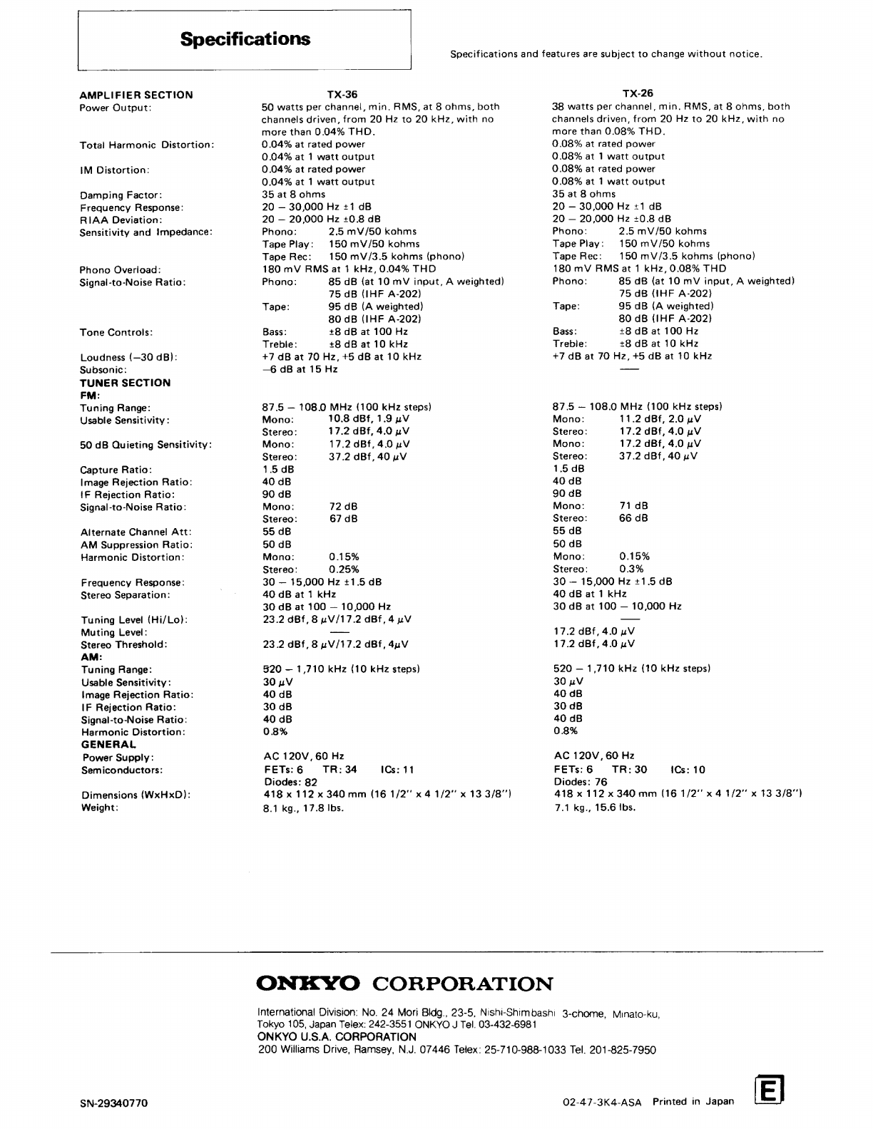
Onkyo TX-26 User manual

Artistry
in
Sound
ONKYVO
***
WARNING
***
TO
PREVENT
FIRE
OR
SHOCK
HAZARD,
DO
NOT
EXPOSE
THIS
UNIT
TO
RAIN
OR
MOISTURE.
e
THE
CABINET
COMPOSITION
OF
THIS
UNIT
IS
VINYL
LAMINATED
STEEL
SHEET.
#
The
serial
number
is
written
on
the
rear
panel
of
this
unit.
Copy
the
serial
number
and
mode!
number
onto
your
warranty
card
and
keep
it
in
a
safe
place.
@
This
apparatus
complies
with
FCC
requirements
part
15
subpart
C,
X-26/3
Quartz
Synthesized
Tuner
Amplifier
Instruction
Manual
ONKYO.
=»
CAUTION
e
The
lightning
flash
with
arrowhead
symbol
within
an
equi-
.
ateral
triangle
is
intended
to
alert
the
user
to
the
presence
o
TO
REDUCE
THE
RISK
OF
ELECTRIC
an
uningulated
‘dangerous
voltage’
within
the
product's
SHOC
K,
DO
NOT
REMOVE
COVER.
enclosure
that
may
be
of
sufficient
magnitude
to
constitute
a
NO
USER-SERVICEABLE
PARTS
INSIDE.
risk
of
electric
shock
to
persons.
REFER
SERVICING
TO
QUALIFIED
e
The
exclamation
point
within
an
equilateral
triangle
is
in-
SERVICE
PERSONNEL.
tended
to
alert
the
user
to
the
presence
of
important
operating
and
maintenance
instructions
in
the
literature
accompanying
the
unit.
CAUTION
RISK
OF
ELECTRIC
SHOCK
DO
NOT
OPEN
—
A

For
Safety
Read
these
safety
precautions
carefuily
before
using
this
unit.
1.
2.
11.
12.
15.
16.
Read
Instructions
—
Ali
the
safety
and
operating
instructions
should
be
read
before
the
unit
is
operated.
Retain
Instructions
—
The
safety
and
operating
instructions
should
be
retained
for
future
reference.
Head
Warnings
—
All
warnings
on
the
unit
and
in
the
operating
instructions
should
be
adhered
to.
Follow
Instructions
—
Ail
operating
and
use
instructions
should
be
followed.
Water
and
Moisture
—
The
unit
should
not
be
used
near
water
—
for
example,
near
a
bathtub,
washbowl,
kitchen
sink,
in
a
wet
basement,
or
near
a
swimming
pool.
Carts
and
Stands
—
The
unit
should
be
used
only
with
a
cart
or
stand
that
is
recommended
by
the
manufacturer.
Wall
or
Ceiling
Mounting
—
The
unit
should
be
mounted
to
a
wall
or
ceiling
only
as
recommended
by
the
manufacturer.
Ventilation
—
The
unit
should
be
situated
so
that
its
location
or
position
does
not
interfere
with
its
proper
ventilation.
For
example,
the
unit
should
not
be
situated
on
a
bed,
sofa,
rug,
or
similar
surface
that
may
biock
the
ventilation
apenings
Or
placed
in
a
built-in
installation,
such
as
a
bookcase
or
cabinet,
that
may
impede
the
flow
of
air
through
the
ventilation
openings.
Heat
—
The
unit
should
be
situated
away
from
heat
sources
such
as
radiators,
heat
registers,
or
other
appliances
(includ-
ing
amplifiers)
that
produce
heat.
Power
Sources
—
The
unit
should
be
connected
to
a
power
supply
only
of
the
type
described
in
the
operating
instructions
or
as
marked
on
the
unit.
Grounding
or
Polarization
—
The
unit
should
be
property
grounded
and
correct
polarization
observed.
Power-Cord
Protection
—
Power-supply
cords
should
be
routed
so
that
they
are
not
likely
to
be
waiked
on
or
pinched
by
items
placed
upon
or
against
them,
paying
particular
attention
to
cords
at
plugs,
convenience
receptacies,
and
the
point
where
they
exit
from
the
unit.
Cleaning
—
The
unit
should
be
cleaned
only
as
recommended
by
the
manufacturer.
Cleaning
of
internal
parts
must
be
performed
only
by
qualified
service
personnel.
Removing
the
cabinet
exposes
you
to
the
danger
of
receiving
an
electric
shock
and
can
even
cause
the
unit
to
malfunction.
From
time
to
time
you
should
wipe
off
the
front
and
rear
panels
and
the
cabinet
with
a
silicon
or
other
soft
cloth.
For
heavier
dirt,
dampen
a
soft
cloth
in
a
weak
solution
of
mild
detergent
and
water,
wring
it
out
dry,
and
wipe
away
the
dirt.
Following
this,
dry
immediately
with
a
clean
cloth.
Do
not
use
rough
material,
thinner,
alcohol,
or
other
chemical
solvents
or
cloths,
since
these
may
damage
the
finish
or
remove
the
panei
lettering.
Power
Lines
—
An
outdoor
antenna
should
be
located
away
from
power
lines.
Outdoor
Antenna
Grounding
—
if
an
outdoor
antenna
is
connected
to
the
receiver,
be
sure
the
antenna
system
is
grounded
so
as
to
provide
some
protection
against
vol
tage
surges
and
built
up
static
charges.
Section
810
of
the
National
Electrical
Code
ANSI/NFPA
No.
70—1981,
provides
information
with
respect
to
proper
grounding
of
the
mast
and
supporting
structure,
grounding
of
the
lead-in
wire
to
an
antenna
discharge
unit,
size
of
grounding
conductors,
location
of
antenna-discharge
unit,
connection
to
grounding
electrodes,
and
requirements
for
the
grounding
electrode.
See
Figure
1.
Periods
of
Nonuse
—
The
power
cord
of
the
unit
should
be
unplugged
from
the
outlet
when
left
unused
for
a
long
period
of
time.
Damage
Requiring
Service
—
The
unit
should
be
serviced
by
qualified
service
personnel
when:
A.
The
power
supply
cord
or
the
plug
has
been
damaged;
or
B.
Objects
have
falien,
or
liquid
has
been
spilled
into
the
unit;
or
C.
The
unit
has
been
exposed
to
rain;
or
D.
The
unit
does
not
appear
to
operate
normally
or
exhibits
a
marked
change
in
performance;
or
E.
The
unit
has
been
dropped,
or
the
enclosure
damaged.
FIGURE
1
EXAMPLE
OF
ANTENNA
GROUNDING
AS
PER
NATIONAL
ELECTRICAL
CODE
INSTRUCTIONS
GROUND
CLAMP
DOWNLEAD
OR
'
LEAD-IN
WIRE
?:
MAST
GROUND
a.b
WIRE
ANTENNA
DISCHARGE
C
TO
RECEIVER
UNIT
“®
GROUND
WIRE
GROUND
CLAMPS
'
SUITABLE
GROUNDING
*;}
ELECTRODE
ORIVEN
“
8
INTO
THE
EARTH
5B1682
(2.44
METERS)
Use
no.
10
AWG
copper
or
No.
8
AWG
aluminum
or
No.
17
AWG
copper-clad
steel
or
bronze
wire,
or
larger
as
ground
wires
for
both
mast
and
lead-in.
Secure
lead-in
wire
from
antenna
to
antenna
discharge
unit
and
mast
ground
wire
to
house
with
stand-off
insulators,
spaced
from
4
feet
(1.22
meters)
to
6
feet
(1.83
meters)
apart.
Mount
antenna
discharge
unit
as
closely
as
possible
to
where
lead-in
enters
house.
18.
Servicing
—
The
user
should
not
attempt
to
service
this
unit
beyond
that
described
in
the
operating
instructions.
All
other
servicing
should
be
referred
to
qualified
service
personne!.
AC
Fuse
and
Speaker
Protection
Fuse
The
fuses
are
located
inside
the
chassis
and
are
not
user
serviceable.
|f
power
does
not
come
on,
contact
your
Onkyo
dealer.
Memory
Preservation
This
unit
does
not
require
memory
preservation
batteries.
A
built-
in
memory
power
back-up
system
preserves
the
contents
of
the
memory
during
power
failures
and
even
when
the
unit
is
unplugged.
The
unit
must
be
plugged
in
and
the
power
switch
turned
on
and
off
once
in
order
to
charge
the
back-up
system.
Note
that
since
this
is
NOt
a
permanent
memory,
the
power
switch
must
be
turned
on
and
off
a
few
times
each
month
to
keep
the
back-up
system
operable.
The
period
of
time
during
which
memory
contents
are
preserved
after
power
has
last
been
turned
off
varies
depending
on
climate
and
the
location
and
placement
of
the
unit.
On
the
average,
memory
contents
are
protected
over
a
period
of
3
to
4
weeks
{a
minimum
of
2
weeks)
after
the
last
time
power
has
been
turned
off.
This
period
is
shorter
when
the
unit
is
exposed
to
very
high
humidity
or
used
in
an
area
with
an
extremely
humid
climate.

Trouble-shooting
Guide
[er
|
Trouble
|
Cause
Remedy
b-
4
|
No
power.
@
AC
fuse
blown.
e
Contact
Onkyo
dealer.
|
L
a
’
Power
but
no
sound.
@
Tape
monitor
on.
@
Switch
to
off.
@
Bad
connections.
-
@
Check
input
leads,
speaker
leads,
pin
plugs,
etc.
e
Speaker
protection
fuse
blown
—
i
@
Contact
Onkyo
dealer.
short-circuit
in
speaker
connections.
|
'
Hum,
low
frequency
noise.
@
Poor
or
no
input
ground.
|
@
Check
outer
conductor
of
input
plugs.
|
:
@
Poor
or
no
phono
motor
ground.
/
@
Check
for
proper
ground
connection,
e
Power
source
hum.
@
Try
reversing
power
plug
in
socket.
——.
_
_
——--—
———-—_—_--—_—__—_<_
Howling
when
the
volume
ts
e
Turntable
and
speakers
are
too
e
Move
them
farther
apart.
turned
up.
close
together.
——
_
oe
oo
im
ee
___.
.
_
——
Rough
or
scratchy
sound.
e
Stylus
of
pick-up
is
worn,
@
Replace.
|
High
range
is
not
clear.
@
Stylus
tip
is
dirty.
i
@
Clean.
e
Treble
control
too
high.
'@
Turn
treble
contro!
down,
jp_
}
-
4
Buzzing
noise
on
AM
|
@
Noise
from
electrical
apparatus
such
e
Move
unit
to
different
position.
|
(particularly
conspicuous
|
as
fluorescent
lamp.
'@Set
up
outdoor
AM
antenna.
|
'
at
night
or
with
weak
stations).
i
eee.
+
ee
ee
ee
--
-
=
+
a
_.
_
——a—
ot
_High
pitched
noise.
;
®
Noise
from
TV.
@
Move
unit
away
from
TV
set.
|
'
Crackling
noise
on
AM
and
FM.
|
e
Noise
caused
by
turning
fluorescent
e
Move
antenna
as
far
as
possible
from
the
;
damp
on
and
off.
fluorescent
lamp.
|
:
@
Noise
from
automobile
ignition.
@
Install
an
FM
outdoor
antenna
as
far
as
possible
from
the
road.
@
Change
the
position
or
direction
of
the
outdoor
antenna.
_——
-
ee
a
_
_
;
|
Signal
strength
indicator
|
@
Station
is
too
strong.
#
Change
to
T-shaped
antenna.
|
(only
TX-36)
increases
e
Multiple
reflection
of
the
radio
@
Use
antenna
which
has
better
directivity
and
select
sufficientiy
but
the
sound
is
waves
because
of
tall
buildings
or
a
point
where
the
distortion
is
least.
distorted
and
the
separation
mountains.
is
bad,
Signal
strength
indicator
_@
Station
is
too
weak.
@
Install
an
outdoor
FM
antenna.
(only
TX-36)
varies
unsteadily.
_®
Stereophonic
FM
broadcasts
e
Change
the
position
or
direction
of
the
Hiss
on
FM.
|
cover
only
about
half
the
outdoor
antenna.
distance
of
an
ordinary
!
broadcast.
be
—_—_--—___-.
-
-
_—___
-
No
station
is
recalled
when
_®
The
power
switch
has
not
been
e
The
memory
contents
are
lost
if
the
power
is
not
a
preset
key
is
pressed.
'
turned
on
for
a
long
time
or
the
turned
on
and
off
a
few
times
each
month.
Store
power
cord
has
been
unplugged
all
stations
in
the
memory
again
and
remember
to
|
far
a
long
time.
turn
power
on
and
off
a
few
times
each
month.
The
tuning
steps
by
which
the
tuned
frequency
decreases
and
increases
on
each
band
have
been
set
at
the
factory
to
the
proper
value
for
the
country
where
each
unit
is
to
be
sold.
If
you
use
the
unit
in
a
country
where
a
different
tuning
step
is
required
or
if
the
broadcast
frequencies
in
your
country
change
so
that
you
can
not
tune
in
radio-stations
precisely,
take
this
unit
to
an
authorized
Onkyo
Service
Center.

=|
|
Front
Panel
Facilities
rn!
@
The
front
panel
design
for
the
TX-36
and
TX-26
differs
slightly
according
to
the
areas
for
which
each
unit
was
manufactured.
For
example,
some
units
have
silver
panels
and
others
are
black.
@
The
features
and
specifications
for
the
TX-36
and
T
X-26
are
slightly
different.
Read
this
manual
carefully
to
operate
the
model
you
have
purchased
correctly.
19
18
5
10)
16
pos
spoof
ute
Aweuie
a
esas
--
-PRISET
STATION»
°
co)
ices
|co
=
-
-
-
a
oo
Db
te
FOTN
TIDY
Svyrios
SE
STATIS
BD
Bravws
F
co
o
[3]
4
5
(6)
7/8)
|}
12)
(13)
(14)
15
Power
Switch
(POWER)
Press
once
to
turn
power
on
and
again
to
turn
power
off.
APR
Indicator
Note:
The
DX/LOCAL
indicator
is
only
on
the
TX-36,
Auto/Manual
Indicator
Preset
Tuning
Indicators
(PRESET
STATION)
Auto/Manual
Tuning
Switches
(TUNING)
AUTO:
Press
to
perform
automatic
tuning.
MANUAL:
Press
to
perform
manual
tuning.
Tuning
Selector
(TUNING)
Press
the
UP
selector
to
raise
the
reception
frequency
and
the
DOWN
selector
to
lower
the
reception
frequency.
Using
the
Tuning
Selector
(Manual
Mode)
First,
press
the
MANUAL
tuning
switch[5)
to
use
the
manual
tuning
mode.
Now,
when
either
side
of
the
tuning
selector
is
held
down,
the
tuned
frequency
will
increase
or
decrease
continuously.
To
tune
ina
station,
press
either
the
UP
or
DOWN
tuning
selector
until
you
are
near
the
frequency
of
the
desired
station.
Then,
after
releasing
the
tuning
selector,
press
again
to
change
the
frequency
in
single
steps
until
the
desired
station
is
precisely
tuned.
Pressing
once
changes
the
frequency
by
100kHz
in
the
FM
band
and
by
10kHz
itn
the
AM
band.
Using
the
Tuning
Selector
(Auto
Mode)
Press
the
AUTO
tuning
switch
[5]
to
use
the
auto
tuning
mode.
Then
press
the
UP
or
DOWN
tuning
selector;
there
is
no
need
to
keep
the
selector
depressed
as
in
the
manual
tuning
mode.
The
tuned
frequency
will
continue
to
increase
or
decrease
unti!
a
broadcast
of
sufficient
strength
is
reached.
To
move
on
to
the
next
broadcast,
press
the
UP
or
DOWN
tuning
selector
again.
When
the
upper
or
lower
end
of
the
frequency
range
\s
reached,
the
displayed
frequency
will
begin
moving
in
the
opposite
direction.
For
example,
when
the
DOWN
tuning
selector
is
pressed,
the
frequency
will
decrease
until
the
lowest
frequency
is
reached
and
then
start
increasing
again
toward
the
highest
frequency
even
though
the
DOWN
tuning
selector
is
not
still
being
held
down.
-~¥—_—
Frequency
range
——+|
Lower
limit
Upper
limit
1.
When
the
DOWN
tuning
selector
is
pressed,
the
frequency
will
decrease
until
the
lower
limit
is
reached.
2.
At
this
point,
the
frequency
will
automatically
begin
increasing
for
as
tong
as
the
DOWN
side
of
the
tuning
selector
is
not
held
down,
Scanning
will
not
stop
for
broadcasts
weak
enough
to
be
suppressed
by
the
muting
circuit.
To
receive
a
weak
FM
broadcast,
set
the
FM
mute/mode
switch
[14]
to
the
OFF
(MONO}
position
and
tune
in
the
FM
broadcast
using
the
manual
tuning
mode.
On
the
TX-36,
an
FM
tuning
evel
switch
[15]
permits
the
muting
level
to
be
switched
between
high
and
low.
In
the
high
position,
scanning
during
automatic
tuning
will
only
stop
for
stations
having
a
high
signal
strength.
To
tune
in
weaker
stations
in
the
automatic
tuning
mode,
set
the
tuning
level
switch
to
the
low
position.
For
even
weaker
stations,
set
the
FM
mute/mode
switch
14]
to
the
OFF
(MONO}
position
(in
which
case
even
stereo
broadcasts
will
be
heard
in
mono).
[7]
FM/AM
Preset
Keys
(PRESET
STATION)
Use
these
keys
to
recall
an
FM
or
AM
station
or
to
store
a
station
in
the
memory.
The
preset
indicator
will
light
to
show
which
key
has
been
used.
Refer
to
the
Memory
Function
section
for
details.
[8]
Tape
Monitor
Switches
and
Indicators
These
switches
permit
two
different
tape
decks
to
be
used
for
recording,
playback
and
dubbing.
Press
once
to
turn
on
and
once
again
to
turn
off.
Note
that
dubbing
can
only
be
performed
from
tape
deck
1
to
tape
deck
2.
eo
Input
Selector
Switches
and
Indicators
PHONO:
Press
this
switch
to
listen
to
the
turntable,
TUNER:
Press
this
switch
to
listen
to
an
AM
or
FM
broadcast.
Treble
Control
(TREBLE)
Adjust
to
strengthen
or
weaken
treble
response.
In
the
center
defeat
position,
the
treble
tone
control
circuitry
is
completely
bypassed.
When
the
treble
control
is
turned
all
the
way
to
the
left,
a
high
cut
filter
is
activated.
11;
Bass
Control
(BASS)
Adiust
to
strengthen
or
weaken
bass
response.
In
the
center
defeat
position,
the
bass
tone
control
circuitry
is
completely
bypassed.
12]
Subsonic
Filter
(SUBSONIC)
(only
TX-36)
Pushing
this
button
cuts
off
all
frequencies
below
15Hz.
This
is
used
to
eliminate
motor
rumble
and
other
inaudible
low
frequency
noises.

(13;
Loudness
Control
(LOUDNESS)
When
listening
at
low
volume
levels,
depress
this
button
to
boost
the
very
high
and
very
low
frequencies
to
provide
a
more
natural
sound.
14)
FM
Mute/Mode
Switch
(FM
MUTE/MODE)
ON(STEREO):
Normal
stereo
reproduction;
monaural
broadcasts
will
be
heard
in
mono.
Weak
FM
broadcasts
will
not
be
heard
because
of
the
muting
circuit.
OFF{MONO):
Both
stereo
and
mono
broadcasts
will
be
heard
in
mono.
During
FM
stereo
reception,
the
stereo
indicator
will
not
light.
Weak
FM
broadcasts
will
be
heard
(in
mono},
(15)
FM
Tuning
Level
Switeh
(FM
TUNING
LEVEL)
{only
TX-36)
This
switch
sets
the
FM
muting
level
to
the
high
or
low
Jevel.
It
should
be
set
to
the
position
that
gives
the
best
results
in
your
area.
HIGH:
Only
strong
focal
stations
will
be
heard.
LOW:
Stations
of
lower
signal
strength
will
also
be
heard.
To
tune
in
stations
suppressed
even
by
the
low
setting,
switch
the
FM
mute/mode
switch
to
the
OFF
(MONO)
position.
(161
Volume
Controi
(VOLUME)
Turn
clockwise
to
increase
the
volume
level.
(171
Balance
Control
(BALANCE)
Use
this
control
to
adjust
the
relative
volume
levels
of
the
left
and
right
speaker
systems.
{18}
FM/AM
Selector
Switches
(BAND
SELECTOR)
Press
one
of
these
switches
to
select
the
FM
or
AM
band,
The
input
selector
must
be
set
to
the
TUNER
position
to
listen
to
a
radio
broadcast.
System
Connections
Connect
to
the
75
ohm
coaxial
cable
terminal
if
your
set
is
equipped
with
one
Outdoor
FM
antenna
:
ca
The
300
ohm
and
75
ohm
terminals
should
not
be
used
together.
Connect
either
one
or
the
other,
not
both.
eel
fhen
using
a
common
FM/
V
antenna,
avoid
using
Ye
TX-26/36
and
the
TV
2t
at
the
same
time
ecause
mutual
inter-
arence
may
occur,
If
you
re
using
a
common
FM/
V
antenna,
use
a
direc-
onal
divider.
cS
Do
not
connect
both
indoor
and
outdoor
FM
antennas.
if
you
decide
to
install
an
Qutdoor
antenna,
be
sure
to
disconnect
the
indoor
feeder
antenna.
75
ahm
coaxial
cable
ofr
{(3C-2V,
5C-2V)
300
ohm
antenna
feeder.
iodels
for
urope,
E}
[193
Memory
Key
and
Indicator
Press
this
key
to
place
a
station
in
the
memory
using
the
FM/
AM
preset
keys
[7].
When
this
key
is
pressed,
the
indica-
tor
lights
for
about
5
seconds.
While
the
indicator
is
lit,
press
one
of
the
preset
keys
to
store
a
station
in
the
memory.
The
indicator
above
the
pressed
preset
key
will
light
up
and
the
memory
indicator
will
go
out
to
indicate
that
memory
operation
has
been
completed.
20|
Frequency
Display
The
frequency
recalled
by
the
FM/AM
preset
keys
[7]
or
tuned
by
the
tuning
selector
[6]
is
displayed
here
in
digital
form
when
the
unit
is
in
the
tuner
mode.
Note
that
even
though
the
frequency
display
and
some
tuning
indicators
remain
lit
when
the
PHONO
input
selector
is
pressed,
reception
is
not
possible.
To
return
to
the
tuner
mode,
the
TUNER
input
selector
must
be
pressed.
2]
Stereo
Indicator
(STEREO
PROGRAM)
This
indicator
lights
when
an
FM
stereo
broadcast
is
being
received.
Note
that
it
does
not
light
when
the
FM
mute/mode
selector
is
in
the
OFF
(MONO)
position.
22}
A
Tuning
Indicator
(TUNED)
(only
TX-26)
Operates
only
in
the
FM
Band
22|
B
Signal
Strength
Indicator
(SIGNAL
STRENGTH)
{only
TX-36)
23)
Speaker
Selector
(SPEAKERS)
This
unit
can
drive
two
pairs
of
speakers
in
pairs
{A
or
B)
or
fours
{A
+
B}.
To
listen
to
both
speaker
systems
at
once,
depress
both
speaker
selectors.
24]
Headphone
Jack
(PHONES)
Stereo
headphones
with
a
standard
binaural
plug
can
be
connected
here.
25]
Low
Frequence
Enhencer
Switch
and
Indicator
(LFE)
This
is
a
switch
for
boosting
a
frequency
much
lower
than
Loudness,
and
is
designed
to
provide
an
effect
at
Low
Level
Volume.
Indoor
feeder
antenna
or
300
ohm
outdoor
antenna
>
&
4
.
‘a
AM
antenna
(outdoor)
SPEAREF
SPEAKER
Only
on
TX-36
;
Toms
‘
ac
“OUTLETS
model
only
_
a
a
————————
“
SOOO
.
General
Tape
Deck
Turntable
BL
P| Oi
QO!
Qs
Ri
USA
&
Canadian
or
CD
Player
Tape
Deck
On
each
pair
of
input
and
output
jacks,
the
jower
jack
(marked
R)
corresponds
to
the
right
channel,
and
the
upper
jack
(marked
L)
to
the
left
channel.
When
jacks
on
other
components
or
connection
cables
are
color-coded,
red
usually
corresponds
to
the
right
channel
(Red=Right).
eld
[ele
SPEAKER
5PE
AREA

AC
Outlet
(UNSWITCHED)
(USA
&
Canadian
models
only)
This
outlet
is
not
switched
on
and
off
by
the
power
switch
on
the
front
panel.
Capacity
is
100
watts.
AC
Outlet
(SWITCHED)
(USA
&
Canadian
models
only)
This
outlet
is
switched
on
and
off
by
the
power
switch
on
the
front
panel.
Capacity
is
100
watts.
Only
the
TX-36
is
equipped
with
a
SWITCHED
outlet.
There
are
no
AC
outlets
at
all
on
models
(1TX-36
and
TX-26)
made
for
some
areas.
FM
Antennas
Depending
on
the
strength
and
quality
of
FM
signals
in
your
area,
the
accessory
T-shaped
antenna
may
give
satisfactory
reception
or
you
may
need
an
external
FM
antenna.
Connect
the
lead
wire
from
the
accessory
T-shaped
antenna
firmly
to
the
terminals
marked
ANTENNA
FM
300
Ohms.
Spread
the
antenna
ona
wall,
preferably
outside
or
on
the
ceiling
and
try
several
positions
to
determine
which
gives
the
best
reception.
If
reception
with
the
T-shaped
antenna
is
unsatisfactory,
install
a
multi-element
external
FM
antenna.
Consult
your
Onkyo
dealer
about
the
right
type
for
your
area.
Connection
is
made
to
the
FM
300
Ohms
terminals
by
means
of
antenna
feeder
wire.
Note:
75
ohm
coaxial
cables
are
more
resistant
to
external
interference
than
300
ohm
feeder
cables.
AM
Antenna
An
AM
loop
antenna
is
attached
to
the
rear
panel
of
this
unit.
Swing
one
end
of
the
antenna
away
from
the
rear
panel
to
the
position
that
gives
the
best
reception.
If
reception
is
stil!
unsatisfactory,
completely
remove
the
loop
antenna
from
the
rear
panel
and
hang
it
on
a
wall
or
other
surface
in
the
position
that
gives
the
best
reception.
Be
sure
the
antenna
is
not
near
speaker
or
power
cords,
televison
sets,
and
motorized
appliances.
When
using
an
outdoor
AM
antenna,
do
not
remove
the
joop
antenna.
Connect
both
antennas
to
the
AM
antenna
terminals.
best
reception.
Speaker
Connections
When
connecting
speakers,
proper
polarity
is
important.
Always
connect
the
(+}
terminal
(red)
on
the
amplifier
to
the
(+)
termina!
on
the
speaker
and
the
(—)
terminal
(black)
on
the
amplifier
to
the
(—)
terminal
on
the
speaker.
Note
that
when
both
the
A
and
B
speaker
selectors
are
depressed,
the
A
and
B
speaker
systems
operate
in
a
series
connection.
If
only
one
pair
of
speakers
is
connected,
no
sound
at
all
will
be
heard.
Speaker
Precautions
e
Suitable
speaker
load
impedance
is
important.
Never
use
speakers
with
ajoad
impedance
of
less
than
4
ohms
with
the
TX-36/26.
@
When
using
only
one
speaker
or
when
you
wish
to
listen
to
monaural,
the
single
speaker
should
never
be
connected
in
parallel
to
both
the
right
and
left
channel
terminals
at
once.
e
Do
not
use
unnecessarily
ong
or
extremely
thin
speaker
leads.
If
the
DC
resistance
of
the
speaker
leads
is
too
high,
the
damping
factor
will
decrease.
Connecting
Speaker
Leads
to
the
Speaker
Terminals
1.
Peel
off
the
insulation
about
15mm
back
from
the
end
of
the
wire.
2.
When
using
stranded
wire,
twist
it
so
that
the
separate
wires
will
not
come
unraveled.
3.
Press
the
speaker
termina:
lever,
insert
the
wire
in
the
hole
and
release
the
lever
to
attach
each
speaker
lead.
4.
Be
sure
to
avoid
short
circuits
in
the
speaker
connections.
Tape
Deck,
CD
Player
and
Other
Components
Connect
the
output
leads
of
the
tape
deck
and
an
additional
audio
component
(Compact
Disc
player,
VTR,
TV,
etc.)
to
the
TAPE
PLAY
and
TAPE
PLAY/CD
jacks.
Connect
the
input
leads
of
the
tape
deck
to
the
TAPE
REC
jacks
of
the
T
X-36/26.
For
more
details,
refer
to
your
tape
deck
owner's
manual.
~
As
shown
in
the
diagrams,
use
the
AM
antenna
either
attached
to
the
rear
panel
or
separated
from
it
to
find
the
position
that
gives
the
Turntable
Be
sure
to
connect
the
ground
(earth)
lead
wire
from
the
turntable
to
the
ground
terminal
(GND).
Lack
of
proper
ground
connection
will
cause
hum.
1.
Place
the
turntable
on
a
firm
shelf
or
deck
free
from
vibrations
(especially
those
generated
by
the
speaker
system).
if
the
turntable
is
permitted
to
pick
up
such
unwanted
vibrations,
not
only
will
the
performance
of
the
TX-36/26
drop,
but
distortion
in
the
bass
frequencies
and
howling
in
the
speakers
may
also
occur,
Check
the
turntable
instruction
manual
for
any
other
precautions.
The
loud
noises
that
occur
when
connecting
and
disconnecting
the
turntable
leads
could
damage
the
speakers.
Always
turn
the
power
switch
off
before
making
connections.
Operations
Note:
Before
turning
power
on,
confirm
that
all
connections
have
been
made
properly.
FM
Reception
(Manual
Mode)
1.
2.
7.
Press
the
TUNER
input
selector
switch
[9}
and
set
the
FM/
AM
selector
switch
[18]
to
FM.
Confirm
that
both
tape
monitor
switches
are
off
(both
indicators
are
off).
If
one
or
both
switches
are
on,
press
once
more
to
turn
them
off.
Press
the
MANUAL
tuning
switch
/5),
To
tune
in
an
FM
station
not
stored
in
the
memory,
press
the
UP
or
DOWN
tuning
selector
[6].
First
keep
the
selector
depressed
until
the
frequency
display
approaches
the
frequency
of
the
desired
station.
Then
release
the
tuning
selector
and
press
it
again
in
single
steps
until
the
desired
frequency
is
tuned
precisely.
Note
that
the
frequency
is
changed
in
100
kHz
steps
when
either
side
of
the
tuning
seiector
is
pressed
in
single
steps.
.
To
recall
a
station
stored
in
the
memory,
simply
press
the
preset
key
[7]
corresponding
to
the
desired
station.
_
The
stereo
indicator
[21]
will
light
up
if
the
broadcast
is
being
received
in
stereo.
The
stereo
indicator
will
not
light
up
if
the
broadcast
is
monaural
or
too
weak
to
be
received
in
stereo.
Adjust
the
volume,
tone
and
other
controls
as
desired.
FM
Reception
(Auto
Mode)
1.
2.
Press
the
TUNER
input
selector
switch
and
set
the
FM/AM
selector
switch
[18]
to
FM.
Press
the
AUTO
tuning
switch
[5]
and
confirm
that
both
tape
monitor
switches
[8]
are
off.
Press
the
UP
or
DOWN
tuning
selector
[6].
The
tuned
frequency
will
continue
to
increase
or
decrease
until
a
sufficiently
strong
broadcast
is
reached.
To
move
on
to
the
next
broadcast,
press
either
tuning
selector
again
depending
on
the
direction
in
which
you
want
to
go.
The
stereo
indicator
21)
will
tight
up
if
the
broadcast
is
being
received
in
stereo.
To
stop
scanning
during
automatic
tuning,
press
the
MANUAL
tuning
switch
[5].
The
frequency
display
will
immediately
stop
increasing
or
decreasing.
AM
Reception
(Manual
Mode}
1.
2.
3.
Press
the
MANUAL
tuning
switch
[5].
5.
6.
Press
the
TUNER
input
selector
switch
[9]
and
set
the
FM/
AM
selector
switch
to
AM.
Confirm
that
both
tape
monitor
switches
are
off.
To
tune
in
an
AM
station
not
stored
in
the
memory,
press
the
UP
or
DOWN
tuning
selector
[6)
in
the
manner
described
above.
Note
that
the
frequency
is
changed
in
10
kHz
steps
when
either
side
of
the
tuning
selector
is
pressed
in
single
steps.
To
recall
a
station
stored
in
the
memory,
simply
press
the
preset
key
[7]
corresponding
to
the
desired
station.
Adjust
the
volume,
tone
and
other
controls
as
desired.
AM
Reception
(Auto
Mode)
1.
Press
the
TUNER
input
selector
switch
[9]
and
set
the
FM/AM
selector
switch
to
AM.

2.
Press
the
AUTO
tuning
switch
[5]
and
confirm
that
both
tape
monitor
switches
:8]
are
off.
3.
Press
the
UP
or
DOWN
tuning
selector
{6].
The
tuned
frequency
will
continue
to
increase
or
decrease
until
a
sufficiently
strong
broadcast
is
reached.
To
move
on
to
the
next
broadcast,
press
either
tuning
selector
again
depending
on
the
direction
in
which
you
want
to
go.
4.
To
stop
scanning
during
automatic
tuning,
press
the
MANUAL
tuning
switch
[5].
The
frequency
display
will
immediately
stop
increasing
or
decreasing.
Memory
Function
This
unit
can
store
up
to
8
FM
and
8
AM
(a
total
of
16)
stations
in
the
memory
for
instant
recall
at
any
time
without
using
the
tuning
selector.
Read
the
following
directions
carefully
to
avoid
mistaken
operations.
1.
Confirm
that
both
tape
monitor
switches
are
off,
press
the
TUNER
input
selector
[9]
and
set
the
FM/AM
selector
(is)
to
the
band
of
the
station
to
be
placed
in
the
memory.
2.
Tune
in
the
broadcast
to
be
placed
in
the
memory
using
the
tuning
selector
[6].
3.
Depress
the
memory
key
[19]
and,
while
the
memory
indicator
remains
lit
{about
5
seconds),
depress
one
of
the
preset
keys
[7].
4.
When
the
preset
key
is
depressed,
the
memory
indicator
will
go
out
and
the
indicator
above
the
depressed
preset
key
will
come
on.
The
frequency
currently
shown
in
the
frequency
display
is
now
stored
in
the
memory.
5.
If
the
memory
indicator
goes
out
before
you
have
depressed
one
of
the
preset
keys,
simply
press
the
memory
key
again
to
give
yourself
another
5
seconds.
6.
Placing
another
broadcast
in
the
same
memory
channel
automatically
cancels
the
station
previously
stored
in
that
channel.
For
example,
if
a
100.1
MHz
station
is
stored
using
the
first
FM/AM
preset
key
and
then
a
105.1
MHz
station
is
stored
using
the
first
FM/AM
preset
key
again,
the
100.1
MHz
station
will
be
repiaced
by
the
105.1
MHz
station,
Notes
Concerning
Memory
Operation
1.
Preset
frequencies
can
be
transferred
to
other
channels.
For
example,
the
FM
station
stored
by
preset
key
number
6
can
be
transferred
to
preset
key
number
1
in
the
following
manner.
1}
Set
the
FM/AM
selector
switch
to
FM.
2)
Press
preset
key
number
6.
3)
Press
the
memory
key
.
(the
memory
indicator
lights)
4)
Press
preset
key
number
1.
5)
The
same
station
is
now
stored
by
both
preset
keys
1
and
6.
2.
When
the
power
is
turned
off
or
when
the
power
cord
is
unplugged
from
the
wall
socket,
the
frequencies
stored
in
the
memory
will
be
preserved
and
the
last
tuned
station
will
be
returned
immediately
when
the
power
is
turned
on
again.
For
example,
if
90.1
MHz
was
tuned
in
when
the
power
was
turned
off,
the
frequency
displayed
when
the
power
is
turned
on
again
will
still
be
90.1
MHz.
Phonograph
Records
1.
Connect
the
turntable
to
the
PHONO
itnputs
and
connect
the
phono
ground
wire
to
the
ground
terminal.
2.
Press
the
PHONO
input
selector
switch
[9]
and
confirm
that
both
tape
monitor
switches
[8]
are
off.
3.
Foliaw
turntable
operating
instructions.
4.
Adjust
the
volume,
tone
and
other
controls
as
desired.
Tape
Playback
1.
Connect
the
output
leads
from
the
tape
deck
to
the
TAPE-1
or
2
PLAY
inputs.
2.
Press
the
TAPE-1
or
TAPE-2
tape
monitor
switch
depending
on
which
pair
of
TAPE
PLAY
inputs
the
deck
is
connected
to.
3.
Follow
tape
deck
operating
instructions
for
playback.
4.
Adjust
the
volume,
tone
and
other
controls
as
desired.
Tape
Recording
of
Radio
Programs
or
Phonograph
Records
1.
Make
all
connections
between
the
tape
deck
and
the
unit
as
shown
in
the
System
Connections
Diagram.
2.
Radio:
Press
the
TUNER
input
selector
switch
[9]
and
set
the
FM/AM
selector
to
FM
or
AM.
Records:
Press
the
PHONO
input
selector
switch
[9].
3.
Put
the
tape
deck
in
the
recording
mode.
The
recording
can
be
monitored
through
the
speakers
or
headphones
as
desired.
Turn
on
the
corresponding
tape
monitor
switch
to
hear
the
signal
that,
having
been
recorded,
is
returnec
from
the
deck
to
the
TX-36/26
(if
the
deck
has
three
heads).
Tape-to-Tape
Duplicating
1.
Connect
two
tape
decks
to
the
unit
as
shown
in
the
System
Connections
Diagram.
2.
Load
the
original
tape
in
tape
deck
1
and
the
blank
tape
in
tape
deck
2.
3.
Press
tape
monitor
switches
1
and
2
[8]
(both
indicators
light).
4,
Put
tape
deck
1
in
the
playback
mode
and
tape
deck
2
in
the
recording
mode.
Follow
tape
deck
operating
instructions,
5.
The
recording
can
be
monitored
through
the
speakers
or
headphones.
If
tape
deck
2
has
three
heads,
the
just-recorded
signal
can
be
monitored.
Set
the
proper
recording
level
using
the
controls
on
the
tape
deck
used
for
recording.
Also,
during
recording
and
dubbing
operations,
never
change
the
positions
of
any
switches
on the
TX-26/36.
e
APR
(Automatic
Precision
Reception)
System
This
unit
is
equipped
with
Onkyo’s
unique
APR
system
that
automatically
controls
the
stereo/mono
reception
modes,
antenna
input
DX/local
setting
(TX-36
only)
and
FM
auto
hi-blend
function
according
to
the
quality
(signai
strength,
distortion,
etc.)
of
the
signal
currently
being
received.
Consequently,
optimum
reception
(the
lowest
distortion
and
highest
S/N
ratio)
is
assured
at
all
times.
The
FM
mute/mode
switch
{!4
should
normally
be
left
in
the
ON(STEREO)
(MB)
position.
Set
to
the
OFF(MONO)
(a:
position
only
to
receive
weak
FM
stations
that
are
suppressed
by
the
muting
circuitry.
In
this
setting,
even
stereo
broadcasts
will
be
received
in
the
monaural
made
(the
stereo
indicator
[21]
will
remain
off)
and
the
APR
stereo/mono
selection
function
will
not
operate.
The
FM
tuning
level
switch
15]
is
also
linked
to
the
APR
system.
Therefore,
the
position
of
this
switch
determines
the
signal
strength
jevel
at
which
APR
will
switch
the
reception
mode
between
stereo
and
mono
{when
the
FM
mute/
mode
switch
is
in
the
ON(STEREO)
position).
re
®
Key
Touch
Tone
(TX-36
only)
A
gentie
beep
is
emitted
to
confirm
when
a
Tuning
control
is
used.
A
rear
panel
switch
is
provided
to
let
you
turn
this
tone
on
and
off
as
required.
|e}

Specifications
AMPLIFIER
SECTION
Power
Output:
Total
Harmonic
Distortion:
IM
Distortion:
Damping
Factor:
Frequency
Response:
RIAA
Deviation:
Sensitivity
and
Impedance:
Phono
Overload:
Signal-to-Noise
Ratio:
Tone
Controls:
Loudness
(—30
dB):
Subsonic:
TUNER
SECTION
FM:
Tuning
Range:
Usable
Sensitivity:
50
dB
Quieting
Sensitivity:
Capture
Ratio:
Image
Rejection
Ratio:
{F
Rejection
Ratio:
Signal-to-Noise
Ratio:
Aiternate
Channel
Att:
AM
Suppression
Ratio:
Harmonic
Distortion:
Frequency
Response:
Stereo
Separation:
Tuning
Level
(Hi/Lo):
Muting
Level:
Stereo
Threshold:
AM:
Tuning
Range:
Usable
Sensitivity:
Image
Rejection
Ratio:
IF
Rejection
Ratio:
Signal-to-Noise
Ratio:
Harmonic
Distortion:
GENERAL
Power
Supply:
Semiconductors:
Dimensions
(WxHxD):
Weight:
SN-29340770
TX-36
50
watts
per
channel,
min.
RMS,
at
8
ohms,
both
channels
driven,
from
20
Hz
to
20
kHz,
with
no
more
than
0.04%
THD.
0.04%
at
rated
power
0.04%
at
1
watt
output
0.04%
at
rated
power
0.04%
at
1
watt
output
35
at
8
ohms
20
—
30,000
Hz
+1
dB
20
—
20,000
Hz
+0.8
dB
Phono:
2.5
mV/50
kohms
Tape
Play:
150mV/50
kohms
Tape
Rec:
150
mV/3.5
kohms
(phono)
180
mV
RMS
at
1
kHz,
0.04%
THD
Phono:
85
dB
{at
10
mV
input,
A
weighted)
75
dB
(IHF
A-202)
Tape:
95
dB
(A
weighted)
80
dB
(IHF
A-202)
Bass:
+8
dB
at
100
Hz
Trebie:
+8
dB
at
10
kHz
+7
dB
at
70
Hz,
+5
dB
at
10
kHz
—6
dB
at
15
Hz
87.5
—
108.0
MHz
(100
kHz
steps)
Mono:
10.8
dBf,
1.9
pV
Stereo:
17.2
dBf,
4.0
nV
Mono:
17.2
dBf,40
nV
Stereo:
37.2
dBf,
40
uV
1.5
dB
40
dB
90
dB
Mono:
72
dB
Stereo:
67
dB
55
dB
50
dB
Mono:
0.15%
Stereo:
0.25%
30
—
15,000
Hz
+1.5
dB
40
dB
at
1
kHz
30
dB
at
100
—
10,000
Hz
23.2
dBf,
8
#V/17.2
dBf,4
nV
23.2
dBf,
8
wV/17.2
dBf,
4uV
520
—
1,710
kHz
(10
kHz
steps)
30
pV
40
dB
30
dB
40
dB
08%
AC
120V,
60
Hz
FETs:
6
TR:
34
ICs:
11
Diodes:
82
418
x
112
x
340
mm
(16
1/2"
x
4
1/2”
x
13
3/8”)
8.1
kg.,
17.8
Ibs.
Specifications
and
features
are
subject
to
change
without
notice.
TX-26
38
watts
per
channel,
min.
RMS,
at
8
ohms,
both
channels
driven,
from
20
Hz
to
20
kHz,
with
no
more
than
0.08%
THD.
0.08%
at
rated
power
0.08%
at
1
watt
output
0.08%
at
rated
power
0.08%
at
1
watt
output
35
at
8
ohms
20
—
30,000
Hz
+1
dB
20
—
20,000
Hz
+0.8
dB
Phono:
2.5
mV/50
kohms
Tape
Play:
150mV/50
kohms
Tape
Rec:
150
mV/3.5
kohms
(phono)
180
mV
RMS
at
1
kHz,
0.08%
THD
Phono:
85
dB
(at
10
mV
input,
A
weighted)
75
dB
(IHF
A-202}
Tape:
95
dB
(A
weighted)
80
dB
(IHF
A-202)
Bass:
+8
dB
at
100
Hz
Treble:
+8
dB
at
10
kHz
+7
dB
at
70
Hz,
+5
dB
at
10
kHz
87.5
—
108.0
MHz
(100
kHz
steps}
Mono:
11.2
dBf,
2.0
uV
Stereo:
17.2
dBf,
4.0
nV
Mono:
17.2
dBf,
4.0
uV
Stereo:
37.2
dBf,
40
uV
1.5d8
40
dB
90
dB
Mona:
71
dB
Stereo:
66
dB
55
dB
50
dB
Mono:
0.15%
Stereo:
0.3%
30
—
15,000
Hz
+1.5
dB
40
dB
at
1
kHz
30
dB
at
100
—
10,000
Hz
17.2
dBf,
4.0
uV
17.2
dBf,4.0uV
520
—
1,710
kHz
(10
kHz
steps)
30
uV
40
dB
30
dB
40
dB
0.8%
AC
120V,
60
Hz
FETs:6
TR:30
iCs:
10
Diodes:
76
418
x
112
x
340
mm
(16
1/2”
x
4
1/2”
x
13
3/8")
7.1
kg.,
15.6
Ibs.
ONKYO
CORPORATION
International
Division:
No.
24
Mori
Bldg.,
23-5,
Nishi-Shimbashi
3-chome,
Minato-ku,
Tokyo
105,
Japan
Telex:
242-3551
ONKYO
J
Tel.
03-432-698
1
ONKYO
U.S.A.
CORPORATION
200
Williams
Drive,
Ramsey,
N.J.
07446
Telex:
25-710-988-1033
Tel.
201-825-7950
02-47-3K4-ASA
Printed
in
Japan
E]
This manual suits for next models
1
Table of contents
Other Onkyo Amplifier manuals

Onkyo
Onkyo AS-V620 User manual

Onkyo
Onkyo A-8015 User manual

Onkyo
Onkyo TX-906 User manual

Onkyo
Onkyo A-9010 User manual

Onkyo
Onkyo A-15 User manual

Onkyo
Onkyo TX-SV515PRO II User manual

Onkyo
Onkyo P-3000R User manual

Onkyo
Onkyo A-SV240 User manual

Onkyo
Onkyo TX-SV727 User manual

Onkyo
Onkyo M-5030 User manual

Onkyo
Onkyo FR-N3X User manual

Onkyo
Onkyo A-8700 User manual

Onkyo
Onkyo TX-SV424 User manual

Onkyo
Onkyo M-282 - Amplifier User manual

Onkyo
Onkyo DV- P303 User manual

Onkyo
Onkyo A-9211 User manual

Onkyo
Onkyo P-308 User manual

Onkyo
Onkyo A-8500 User manual

Onkyo
Onkyo EA-70 User manual

Onkyo
Onkyo TX-840 User manual