manuals.online logo
Brands
  1. Home
  2. •
  3. Brands
  4. •
  5. Onkyo
  6. •
  7. Home Theater System
  8. •
  9. Onkyo HT-S3900 User manual

Onkyo HT-S3900 User manual

Other manuals for HT-S3900

1

Other Onkyo Home Theater System manuals

Onkyo SKC-340C User manual

Onkyo

Onkyo SKC-340C User manual

Onkyo HT-S790(B)/(S) User manual

Onkyo

Onkyo HT-S790(B)/(S) User manual

Onkyo HTS590 - 5.1 Channel Component Home Theater Audio... User manual

Onkyo

Onkyo HTS590 - 5.1 Channel Component Home Theater Audio... User manual

Onkyo HT-S790 User manual

Onkyo

Onkyo HT-S790 User manual

Onkyo HT-S870 User manual

Onkyo

Onkyo HT-S870 User manual

Onkyo S770 - HT Home Theater System User manual

Onkyo

Onkyo S770 - HT Home Theater System User manual

Onkyo TX-NR609 Mounting instructions

Onkyo

Onkyo TX-NR609 Mounting instructions

Onkyo HT-R960 User manual

Onkyo

Onkyo HT-R960 User manual

Onkyo HTP-550B User manual

Onkyo

Onkyo HTP-550B User manual

Onkyo TX-SR308 User manual

Onkyo

Onkyo TX-SR308 User manual

Onkyo HT-R340 User manual

Onkyo

Onkyo HT-R340 User manual

Onkyo Liverpool L - MS30 User manual

Onkyo

Onkyo Liverpool L - MS30 User manual

Onkyo HT S3200 Specification sheet

Onkyo

Onkyo HT S3200 Specification sheet

Onkyo HT-S5100 Specification sheet

Onkyo

Onkyo HT-S5100 Specification sheet

Onkyo HT-S780 User manual

Onkyo

Onkyo HT-S780 User manual

Onkyo HT-S894(B) User manual

Onkyo

Onkyo HT-S894(B) User manual

Onkyo HT-S3100 User manual

Onkyo

Onkyo HT-S3100 User manual

Onkyo HT-S7300 User manual

Onkyo

Onkyo HT-S7300 User manual

Onkyo HT-S3500 User manual

Onkyo

Onkyo HT-S3500 User manual

Onkyo HT-S4100 Specification sheet

Onkyo

Onkyo HT-S4100 Specification sheet

Onkyo HT-S8400 Specification sheet

Onkyo

Onkyo HT-S8400 Specification sheet

Onkyo PTS-303 User manual

Onkyo

Onkyo PTS-303 User manual

Onkyo HT-R960 User manual

Onkyo

Onkyo HT-R960 User manual

Onkyo LS5200 User manual

Onkyo

Onkyo LS5200 User manual

Popular Home Theater System manuals by other brands

Samsung HT-DL200 instruction manual

Samsung

Samsung HT-DL200 instruction manual

Samsung HT-ES6600 user manual

Samsung

Samsung HT-ES6600 user manual

Curtis DVD6010 instruction manual

Curtis

Curtis DVD6010 instruction manual

Philips MCD716/12 user manual

Philips

Philips MCD716/12 user manual

Sherwood ST-4108 operating instructions

Sherwood

Sherwood ST-4108 operating instructions

Philips HTS5520/12 quick start

Philips

Philips HTS5520/12 quick start

Sony BDV-T57 Notices and Licences

Sony

Sony BDV-T57 Notices and Licences

LG HT503PHW owner's manual

LG

LG HT503PHW owner's manual

Samsung HT-ES4200K user manual

Samsung

Samsung HT-ES4200K user manual

Samsung HT-P10 instruction manual

Samsung

Samsung HT-P10 instruction manual

Philips HTS5131 User manaul

Philips

Philips HTS5131 User manaul

Goodmans GDVD19SWS user manual

Goodmans

Goodmans GDVD19SWS user manual

Moxi media center user guide

Moxi

Moxi media center user guide

Samsung HT-EM35 user manual

Samsung

Samsung HT-EM35 user manual

Sony BDV-N990W installation guide

Sony

Sony BDV-N990W installation guide

Manta GK-500 user manual

Manta

Manta GK-500 user manual

Sharp SBW800 user manual

Sharp

Sharp SBW800 user manual

Philips HTS3541 user manual

Philips

Philips HTS3541 user manual

manuals.online logo
manuals.online logoBrands
  • About & Mission
  • Contact us
  • Privacy Policy
  • Terms and Conditions

Copyright 2025 Manuals.Online. All Rights Reserved.

Service Manual
Published by Onkyo & Pioneer Corporation Grobal CS Department
SAFETY-RELATED COMPONENT WARNING!! : COMPONENTS IDENTIFIED BY MARK ON THE SCHEMATIC DIAGRAM AND IN THE PARTS LIST ARE CRITICAL FOR RISK OF FIRE AND ELECTRIC SHOCK. REPLACE THESE COMPONENTS WITH ONKYO
PARTS WHOSE PART NUMBERS APPEAR AS SHOWN IN THIS MANUAL. MAKE LEAKAGE-CURRENT OR RESISTANCE MESUREMENTS TO DETERMINE THAT EXPOSED PARTS ARE ACCEPTABLY INSULATED FROM THE SUPPLY CIRCUIT BEFORE
RETURNING THE APPLIANCE TO THE CUSTOMER.
This service manual is intended for qualified service technicians; it is not meant for the casual do-it-yourselfer. Qualified technicians have the necessary test equipment and tools, and have been trained to properly and safely repair complex products
such as those covered by this manual.
Improperly performed repairs can adversely affect the safety and reliability of the product and may void the warranty. If you are not qualified to perform the repair of this product properly and safely, you should not risk trying to do so and refer the repair
to a qualified servicetechnician.
Ref.No. 4628
Pre Issue (Feb-2017)
HT-S3900
= HT-R397 + HTP-395(SKF-395, SKC-395, SKR-395, SKW-395)
HT-S3900
5.1-Channel Home Theater System
Title Page
CONTENTS
✔Title Page (This page)
✔Note for Parts List
✔Panel
✔Reset
✔Firmware
✔Hookup and Setting
✔Trouble Shoot
✔Schematic Diagram
✔Exploded View
✔Appendix
HT-R397SKF-395
SKC-395
SKR-395 SKW-395
543
2
1 6
D
C
A
B
D
C
A
B
543
2
1 6
Note for Parts List
COMMON
D 120V AC
G 220~230V
H 220~230/240V
J 100V AC
M 220~240V AC
P 230V AC
U 100~240V AC
V 110~240V
W 120V/220~240V
Speaker System (without AMP.) :
0 Passive Subwoofer
F Front Speaker
C Center Speaker
R Rear Speaker
B Back Speaker
A Australia
B United Kingdom
C North American
D USA
F Taiwan
J Japan
K Korea
L Russia
P Europe
Q Hong Kong
R China
S Brazil
T Thai
U Worldwide
Speaker System (without AMP.) :
L Left channel
R Right channel
0 Center channel
Voltage(電圧記号) Destination(仕向地記号)
When parts list is EXCEL file, please refer to the following explanation about file name.
P L _ T X – S R 3 4 3 ( B ) M J J . x l s x
Model No. Color
File Name of Parts List File (EXCEL File)
(X) Not related to color
(B) Black (M) Wood
(BR) Brown (O) Orange
(C) Cherry (P) Pink
(G) Gold (R) Red
(GR) Green (S) Silver
(H) Gray (V) Violet
(K) Black (W) White
(L) Blue (Y) Yellow
(LB) Light Blue
Destination(仕向地記号)
Voltage(電圧記号)
Look at the rear panel serial number 6 digit.
○○○○○J○○○○○○○○○○
Look at the rear panel serial number 5 digit.
○○○○J○○○○○○○○○○○
Color(色記号)
543
2
1 6
D
C
A
B
D
C
A
B
543
2
1 6
HT-S3900
Panel
Front Panel
Remote Control Unit
Accessory
RC-928R
Dimensions : 435 mm (W) x 168 mm (H) x 326.5 mm (D) (171/8 in. (W) x 65/8 in. (H) x 1213/16 in. (D))
Weight (without package) : 7.7 kg (16 lb 15 oz)
• Remote control
• AAA size IEC R03 dry cell batteries (to confirm
system operation) x2
• AM loop antenna
• FM wire antenna
• Speaker cables (3 m/10 ft.) x4
• Speaker cables (8 m/26 ft.) x2
• Non-Skid Pads x20
CD TUNER
TV
BD/DVD STRM BOXCBL/SAT GAME USB
SURROUNDSTEREOBLU E TOOTH
LISTEN ING MODE
HOME ENTER RETURN
TUNIN GPRESET
DSP
TONE
AV RECEIVER
HT-R397
PHONES
ON / STANDBY
MASTER VOLUME
USB
5V/0.5A
RECEIVER
SURR
TREBLE
DSP
AUDIO SEL
DISPL AY
TUNER
EDIT SLEEP
TUNING +
TUNING -
PRESET -PRESET +
LATE NIGHT
TOP MENU
BAND
QUICKMENU
CBL/S AT
STRM BOX
BD/DVD
Reset
543
2
1 6
D
C
A
B
D
C
A
B
543
2
1 6
HT-S3900
How to Reset the Unit
Use this procedure to reset all the receiver's settings
to the factory default. Use the front panel controls to
do this.
1. Switch the receiver into standby.
2. While holding down STEREO, press and hold
ON/STANDBY for about two seconds.
3. When you see RESET? appear in the display,
press SURROUND. OK? shows in the display.
4. Press DSP to confirm.
Firmware
543
2
1 6
D
C
A
B
D
C
A
B
543
2
1 6
How to Check Firmware Version / How to Update Firmware
HT-R397
Check to the software virsion of MAIN, HDMI & CEC (SUB) microcomputers
1. Make sure that the main unit is in STANDBY mode.
Press and hold about 3 seconds the both of " ENTER " and " STANDBY/ON " keys as same time,
Then it is appeared firmware version number.
At this time, When you press the " ENTER "key to display each UCOM version, Each time the " ENTER "key is
pressed, then indications on the FL display change as follows:
2. Turn the unit off.
MAIN Ucom "ENTER"
MAIN Xx.xx "ENTER" "ENTER" "ENTER"
SUB Ucom
SUB
zzz.zz
CEC
CEC
Vy,yy DSP
firmware All segments
lit.
"ENTER"
Firmware
543
2
1 6
D
C
A
B
D
C
A
B
543
2
1 6
HT-R397
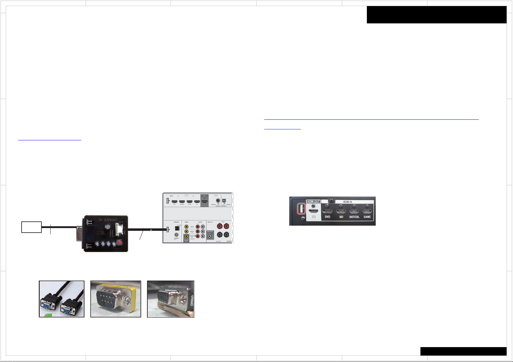
[Necessary Tools and Connections]
1 MAIN microcomputer
• PC with a serial port
•RS-232C cable (9-pin to 9-pin, straight cable) (Marketing product)
•UPDATE jig: GGF1642 (with 10P to 10P FFC)
• Firmware
• Firmware Writer Application for PC
(Flash Programmer M16C Flash Starter M3A-0806 Software)
https://www.renesas.com/
Connect as shown in the below figure and follow the procedure as below
1. Install the software for updating on the PC
2. Unplug the AC Cord of the main unit
3. Insert the FFC with its contact surface facing the " mark.
2 HDMI & CEC (SUB) microcomputer
• PC with a USB port
•USB cable (Marketing product)
•UPDATE jig: GGF1642 (with 10P to 10P FFC)
• Firmware
• Firmware Writer Application for PC
(Cypress/Spansion FLASH MCU Programmer for FM0+/FM3/FM4)
http://www.spansion.com/support/microcontrollers/developmentenvironment/Pages/mcu-
download.aspx
Connect as shown in the below figure and follow the procedure as below
1. Install the software for updating on the PC.
2. Unplug the power cord of the main unit.
Connect the FFC of the updating jig for updating to the main unit.
(Orient the FFC so that the conductive surface of
the connector faces the triangular a symbol.)
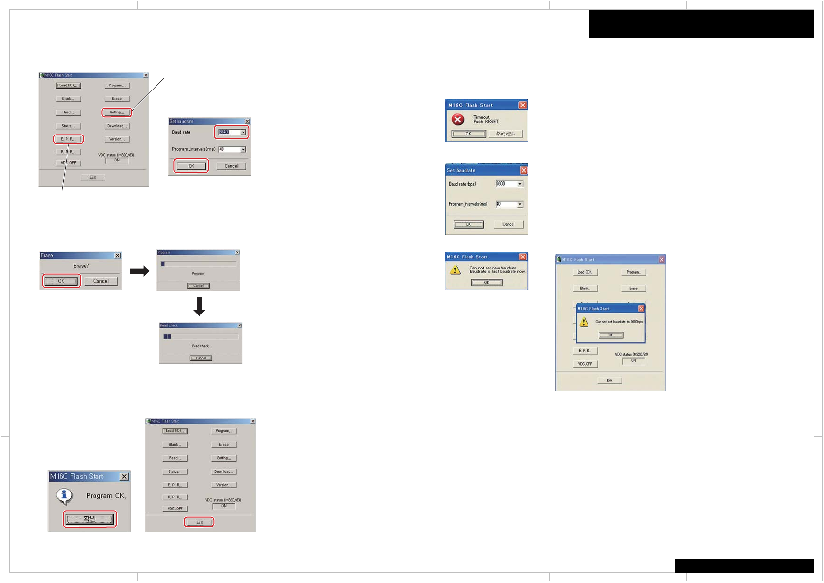
3. Start the software for updating on the PC.
No Necessary connect Main and HDMI&CEC at the same time
When you update Main, you connect Main only.
When you update HDMI&CEC, you connect HDMI&CEC only.
Preparation of Update
When you have no “UPDATE jig GGF1642,
Please order ONKYO service parts dept.
Straight Cable Adapter JIG's side
10P
RS-232C
Straight cable
PC (MAIN
microcomputer)
Rear side
10P to 10P FFC
UPDATE jig
GGF1642
Firmware
543
2
1 6
D
C
A
B
D
C
A
B
543
2
1 6
How to Update (Main MCU) 1/5
HT-R397
Microcomputers update
[Procedures]
for MAIN microcomputer
1. Unplug the AC cord.
Connect the FFC cable.( MAIN microcomputer )
Start up application "FlashSta" on the PC.
2. Plug the AC cord. (STANDBY mode)
For updating of the MAIN microcomputer, proceed with
the following steps in STANDBY mode.
Select for COM port.
[ if the following messages are displayed ]
Please push the cancel button and press the JIG's
RESET button.
And confirm a connection of FFC.
Please return to procedure 1.
3. Press the OK button.
3 Press OK button
to go to next step.
2. Enter ID.
Enter "ff" in all field.
1 Selection of upgrade file
Press the OK
2 Enter ID.
Press the OK button.
4. Select the update file and enter ID.
Note:
You need COM port number on Windows system
“My computer”, “Right Click”, “Properties”, “Device manager”
Click COM port properaties and Make sure COM port number.
Firmware
543
2
1 6
D
C
A
B
D
C
A
B
543
2
1 6
How to Update (Main MCU) 2/5
HT-R397
5. Set speed update and update the MCU.
1 Set speed of update.
Press the OK button.
1 Set speed of update. Set
Baud rate to 38400.
2 Update the MCU.
E.P.R=>Erase+Program+Read
2 Update the MCU
Press the E.P.R … button
Click on "Open" 3 to open the File Selection window.
Select Intel Hex files (*.hex) in File Type.
If the following messages are displayed, shut the
update program down, and start the update again
from step 1.
Select the 9600 of the Board rate
then press the OK button
Press the OK button. Press the Exit button.
Please wait for until this window
disappears.
6. Update Finished MAIN microcomputer. 7. Unplug the AC cord.
Disconnect the FFC cable.
Push the JIG’s RESET button during 1
sec.
Press the OK button.
Firmware
543
2
1 6
D
C
A
B
D
C
A
B
543
2
1 6
How to Update (HDMI Sub MCU) 3/5
HT-R397
for HDMI & CEC (SUB) microcomputer
1
23
4
[Procedures]
To perform updating, proceed as follows:
1. Set the values for Target MCU and Crystal Frequency, as
follows:
Target MCU: MB9AF156M/N/R 1
Crystal Frequency: 4MHz 2
2. Specify the software file to be updated.
Click on "Open" 3 to open the File Selection window.
Select Intel Hex files (*.hex) in File Type
3. Specify the COM PORT.
Click on "Set Environment" 4 to open the Environment Setting window.
Assign the COM PORT number 5, according to the environment.
Click on "OK" 6to close the Environment Setting window.
5
6
7
Click on "Full Operation (D+E+B+P)"7.
5. After the window shown below is displayed, turn the main unit on.
6. Press the Reset button of the updating jig for updating.
7. When it is appeared below window, Then power turn on unit (ON)
8. Click on "OK" 8.
8
Firmware
543
2
1 6
D
C
A
B
D
C
A
B
543
2
1 6
How to Update (HDMI Sub MCU) 4/5
HT-R397
9. The indications in the window change, as indicated
below:
10. Updating has been successfully completed if
"Full Operation OK!" is displayed.
Note:
If an error message like the one shown below is displayed, after checking the
connection of the updating jig for updating and the COM PORT setting, start
updating again from Step 1.
11. Turn the main unit off then disconnect the updating jig for updating.
12. Perform Factory Reset on the main unit.
Or You have to make sure that It is necessary to turn on the unit at procedure 7