Opel CORSA-E RALLY 2022 User manual


V2, 02/2022 Page 2 of 293
VEHICLE DOCUMENTATION
PREFACE
We are proud that you decided to purchase an Opel Corsa-e Rally, the latest result of Opel´s profound
experience in the development and construction of sports, rally and racing cars.
The following document give the user an option to consult all necessary data, settings and operating
instructions for servicing and operating your competition vehicle. It serves as an aid for working on the
Opel Corsa-e Rallye vehicle and in no way replaces the technical competence qualification of drivers
and pit crew. This competence is a prerequisite for the correct use of this manual. Any damage resulting
from incorrect maintenance / installation is considered “customer caused” and the manufacturer
cannot be held liable.
It is strongly recommended that all relevant operating instructions given in this manual are read
carefully before the vehicle is driven for the first time.
Opel Motorsport assumes no responsibility for third-party components . Please note the operating
instructions of the respective provider.
Illustrations, descriptions, photographs and schemes should complete the information given in text
form. Opel Motorsport cannot be held responsible for content that deviates from local laws and
regulations.
Information not contained in this manual must be requested from Opel Motorsport.
SYMBOLS USED WITHIN THIS MANUAL
Symbols
Meaning
Notice
Contains helpful information to make work easier and to avoid problems.
WARNING
Text marked with Warning provides information about risk of accident or injury. Failure to
follow these instructions can result in injury.
CAUTION
Text marked with Caution informs about possible damage to the vehicle. Failure to follow
these instructions can result in vehicle damage.
Essential
Contains important information for safe working. Failure to follow these instructions can
result in injury.
VERSION HISTORY
Version
Date
By
Creation / Amendment
See Page
Contained in chapter
1
03/2021
NHo
Creation of the original version
All
2
02/2022
MEi
Revision
26, 90, 256
1.5.3, 1.5.10, 4.1

V2, 02/2022 Page 3 of 293
VEHICLE DOCUMENTATION
TABLE OF CONTENT
1. TECHNICAL DOCUMENTATION ................................................................ 5
2. DRIVER HANDBOOK.................................................................................... 194
3. TIGHTENING TORQUES............................................................................... 205
4. LIFETIME TABLE ........................................................................................... 255
5. APPENDIX ..................................................................................................... 258
List of abbreviations
A ...........................................................Ampere
ABS..............................Anti-lock braking system
AC.........................................Alternating current
BEV.................................Battery electric vehicle
DC.................................................Direct current
ECU ................................. Electronic control unit
EFK......................... Electrically qualified person
ESP..........................Electronic stability program
FEA................................Finite element analysis
FFSAFederation Francaise de Sport Automobile
FIA .....Fédération Internationale de l'Automobile
GND....................................................... Ground
hp...................................................Horse Power
HV.................................................. High voltage
kg.........................................................Kilogram
km..................................................... Kilometers
km/h....................................Kilometers per hour
kW..........................................................Kilowatt
kWh ...............................................Kilowatt-hour
L1 .............................................................Line 1
L2 .............................................................Line 2
L3 .............................................................Line 3
mꭥ .........................................................Milliohm
Mꭥ. .....................................................Megaohm
mm ..................................................... Millimeter
N ............................................................Neutral
NCAP...................New car assessment program
Nm................................................Newton meter
OBC.........................................Onboard-charger
PE..............................................Protective earth
SoC...............................................State of chare
SS................................................. Special stage
TC.............................................. Traction control
V ................................................................. Volt
vEFK....Responsible electrically qualified person
VIN ....................... Vehicle identification number

V2, 02/2022 Page 5 of 293
TECHNICAL DOCUMENTATION
TECHNICAL DOCUMENTATION1.
1.1 GENERAL OPERATION....................6
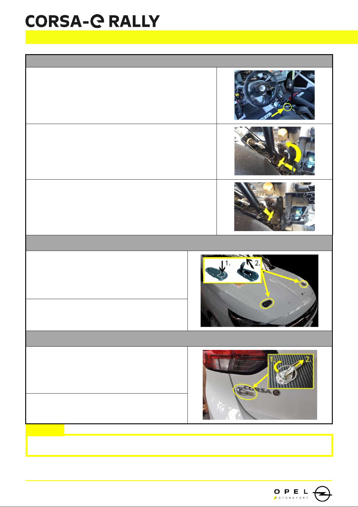
1.1.1 Specific vehicle operations.................... 6
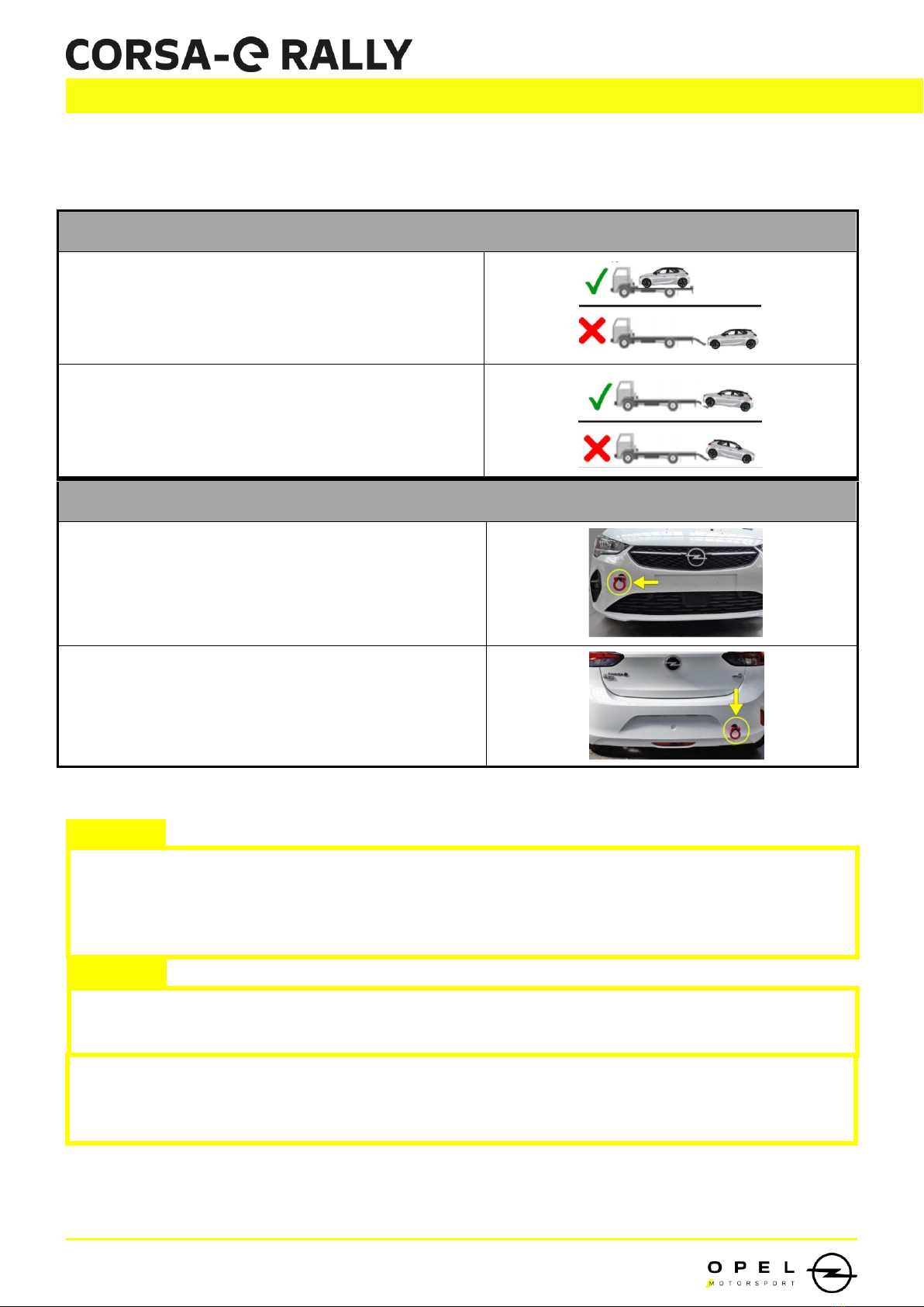
1.1.2 Towing transport .................................. 9
1.2 TECHNICAL SPECS ........................ 10
1.3 SAFETY SPECS .............................. 11
1.4 SAFETY INSTRUCTIONS ................ 12
1.4.1 Rescue Sheet .......................................14
1.4.2 Special Safety Precautions...................18
1.4.3 Case of Fire..........................................19
1.4.4 Safety Messages on the Display...........21
1.5 SERVICE GUIDELINES –OPERATING
INSTRUCTIONS .................................. 22
1.5.1 Operation Symbols ..............................22
1.5.2 Charging .............................................23
1.5.3 HV-system ...........................................25
1.5.4 Fluids...................................................55
1.5.5 Underbody protection plates...............56
1.5.6 Lifting the vehicle ................................57
1.5.7 Vehicle front ........................................59
1.5.8 Vehicle rear .........................................71
1.5.9 Doors...................................................77
1.5.10 Powertrain .........................................83
1.5.11 Cooling circuit................................... 98
1.5.12 Air conditioning circuit.....................116
1.5.13 Wheels............................................. 133
1.5.14 Brake system ................................... 135
1.5.15 Suspension....................................... 150
1.5.16 Steering ...........................................168
1.5.17 Seat ................................................. 175
1.5.18 Night lamp.......................................176
1.5.19 Speakers .......................................... 177
1.6 KEY, DOORS AND WINDOWS ..... 178
1.6.1 Automatic locking .............................179
1.6.2 Power windows ..................................179
1.6.3 Heated rear window ..........................180
1.7 INSTRUMENT AND CONTROLS ... 180
1.7.1 Windscreen wiper and washer ...........180
1.7.2 Warning ligths and indicators............181
1.7.3 Displays .............................................182
1.7.4 Vehicle messages ..............................183
1.8 LIGHTING................................... 183
1.8.1 Exterior lighting .................................183
1.8.2 Interior lighting..................................185
1.9 CLIMATE CONTROL.................... 185
1.9.1 Electronic climate control system.......185
1.9.2 Air vents ............................................187
1.9.3 Maintenance .....................................187
1.10 DRIVING AND OPERATING ....... 187
1.11 VEHICLE CARE.......................... 188
1.11.1 Vehicle checks .................................188
1.11.2 Bulb replacement.............................189
1.11.3 Electrical system ..............................190

V2, 02/2022 Page 6 of 293
TECHNICAL DOCUMENTATION
Electrical disconnect switch
Fire extinguishing system
Electrical disconnect switch
Fire extinguishing system
1.1 GENERAL OPERATION
1.1.1 SPECIFIC VEHICLE OPERATIONS
1. To start the vehicle, both (2x) Emergency switches must be turned on. You will find one on the
outside of the car near the wipers and one inside the car on the switch panel.
2. To switch on the ignition, the start/stop switch next to the steering wheel must be pressed. In
order to be ready to drive, the start/stop switch and the brake pedal must be pressed at the
same time. “Ready” appears on the display.
3. Exterior emergency switches
4. Interior emergency switches
5. If the vehicle is not moved for a long period of time, the battery must be disconnected using the
external emergency switch.
6. The jack and wheel wrench must be hung in the holders provided and locked with all installed
safety locks before driving.
7. GEAR LEVELS
P Park position
R Reverse gear
N Neutral
D Drive mode
Low regenerative braking.
Recommended for road sections and special stages.
B Drive mode
High regenerative braking.
Recommended for braking on road sections.

V2, 02/2022 Page 7 of 293
TECHNICAL DOCUMENTATION
8. DRIVE MODES
Sticker
Drive-mode
Text displayed in cluster
Rain mode
oReduced torque characteristic for slippery
surface.
oSteering setting „Sport“ from series vehicle
with reduced power steering.
Sport
Dry mode (Automatically activated)
oSpecial pedal map for rally cars to ensure
full performance on dry tracks.
oSteering setting „Normal“ from series
vehicle.
“No text”
Street mode
oEco setting from series vehicle.
oSteering calibration „Normal“ from series
vehicle.
Eco
9. SAFE PARKING
Put gearbox lever on (P).
Switch Ignition OFF by pressing the Start/Stop switch.
Wait 2 minutes until the ECU monitoring device is
switched off.
Activate both external EMERGENCY OFF
oYou will find both EMERGENCY OFF switches in
the area of the wiper arms at the front of the
vehicle.
Turning off the the main switch too early can cause the parking actuator to lose position. This could
cause a system error that can only be cleared with a service laptop.
CAUTION

V2, 02/2022 Page 8 of 293
TECHNICAL DOCUMENTATION
10. PARKING WITH FLY-OFF-HANDBRAKE
Location of fly-off-handbrake locking mechanism.
Turn the mechanism upwards to lock the fly-off-
handbrake.
Fly-off-handbrake locked.
11. BONNET OPENING / CLOSING
1. Unlock the lever by pressing the latch.
2. Turn the lever to move the spline out the
latch.
3. Proceed in reverse order to close it.
12. TAILGATE OPENING / CLOSING
1. Turn the safety ring to unlock the spline.
2. Pull the spline out of the latch.
3. Proceed in reverse order to close it.
Before driving, the bonnet and the tailgate must be closed and locked with the locking mechanisms
provided.
CAUTION

V2, 02/2022 Page 9 of 293
TECHNICAL DOCUMENTATION
Check before towing:
Lever in Neutral position (N)
Ignition OFF
Emergency switch OFF
CAUTION
1.1.2 TOWING TRANSPORT
TOWING TRANSPORT
Tow on a platform.
Tow with the front wheels lifted.
TOWING HOOKS
Front tow hook.
Rear tow hook.
With all wheels on the ground, only use the tow hooks to move the vehicle out of danger zones for
short distances (max. 100m) and at a maximum speed of 6 km/h.
CAUTION
The HV-system does not increase the risk of electrocution in water.
If possible, remove the vehicle from the water and begin the vehicle deactivation process.

V2, 02/2022 Page 10 of 293
TECHNICAL DOCUMENTATION
1.2 TECHNICAL SPECS
Electric engine:
Synchronic
Power:
100 kW (136 hp)
Torque:
260 Nm
Battery
(capacity):
Lithium-Ion, 50 kWh
0 –50 km/h:
2,8 seconds
0 –100 km/h:
8,1 seconds
Top speed:
150 km/h
0 –80 % SoC:
30 minutes with 100 kW charger
Driving modes:
RACE DRY, RACE WET, STREET
Transmission:
Front wheel drive with LSD differential
Suspension:
Bilstein Rally suspension, Front: McPherson strut with uniball joints
Rear: Torsion beam axle with Panhard rod
Wheels:
7 x 17, ET20
Brakes:
Brembo 4-piston brake calipers, internally ventilated, 332x28 mm front discs,
264x12 mm rear discs, hydraulic fly-off hand brake
Electric:
ESP, ABS and TC deactivated
Rally computer and RALLYSAFE system
Weight:
about. 1.530 kg (empty weight)
Dimensions:
Length: 4060 mm
Width: 1770 mm
Height: 1440 mm
Wheelbase: 2540 mm
Body-In-White:
Lightweight body-in-white based on eCMP platform with minimum sealing and
without anti-vibration mat; high-strength safety cage fully FEA calculated; 4 car
lifting points integrated in rocker
Underbody
protection:
Steel underbody protection plate to protect drivetrain; aluminium underbody
protection plate to protect HV-battery

V2, 02/2022 Page 11 of 293
TECHNICAL DOCUMENTATION
Options
Spare tire kit which includes spare tire with rim, car jack, brackets for spare
tire and wheel cross.
Communication kit which includes Tripmaster Monit Rally Q20 for recce, Stilo
intercom amplifier with two Stilo WRC DES headsets for liaison.
Accessory kit which includes co-driver reading lamp, night lamp Lazer Triple-
R 1000 Elite, Sparco helmet
Nets and map net.
Security kit including rallysafe provisions (cable and holder).
A Juice Booster pack is proposed as a seperate option. It includes high
quality, high performance and fast charger. It comes with a set of eight plug
adaptators for european sockets.
1.3 SAFETY SPECS
The Corsa e-Rally has a comprehensive safety concept. A Master Alarm Indicator monitors the
operational status of the high-voltage (HV) power system. The HV system can be switched off
automatically or manually from inside and outside the car. The battery pack is safely protected under
the floor and meets the highest rally racing standards.
Safety cell conforming FIA standards and homologated by the FFSA
The Body-in-white of the serial vehicle meets the requirements of Euro NCAP for front and side
impact.
FIA homologated fire extinguishing system
Specific protection for high-voltage (HV) system and underfloor battery compound
HV shutdown in the event of an accident/impact
Specific HV security system with main alarm indicator (lights/sound)
Specific battery protection
Sound module –for safety reasons and to present attractiveness and dynamics

V2, 02/2022 Page 12 of 293
TECHNICAL DOCUMENTATION
1.4 SAFETY INSTRUCTIONS
The procedures detailed in this document must only be performed by technically skilled
personnel with sufficient background in motor racing.
The tightening torques can be found in Chapter 3 (see Page 205).
If in doubt, contact Opel Motorsport technical support immediately.
After each competition event, a visual inspection of all safety-relevant components must be
carried out. Among other areas that require special attention:
oSuspension components
oUnderbody protective plates and mounts.
The manufacturer cannot be held responsible for poor performance, damage or defects caused
by improper handling and/or failure to follow the service procedures outlined herein.
IDENTIFICATION OF HV - VEHICLES
In Germany: last digit on licence plate could be an
„E“.
Warning triangles with flash on HV-components.
HV-wirings are ORANGE.
Any personnel working on an electric vehicle must have an electric vehicle specific training and authorization
to work on these vehicles. Please observe the regulations applicable in the respective country.
WARNING
Please check the tightening torques of all important screws after the first run with the car.
WARNING

V2, 02/2022 Page 13 of 293
TECHNICAL DOCUMENTATION
HV-STATUS INDICATION IN THE SERVICE PARC
Symbol
Definition
Service Work
Vehicle
Service Work
HV-system
HV-system off, checked and
secured
HV-system active
Vehicle switched off
System error at HV-system

V2, 02/2022 Page 14 of 293
TECHNICAL DOCUMENTATION
1.4.1 RESCUE SHEET

V2, 02/2022 Page 16 of 293
TECHNICAL DOCUMENTATION
The vehicle is equipped with a security system that shows the current status of the HV system visually
and acoustically. The meanings of the different colors and the acoustic signal are explained here.
HV-SYSTEM MASTER ALARM INDICATION
Master alarm indicator
Description
Situation
NO LIGHTS
1) Vehicle running
Vehicle moves faster than
6km/h
2) Vehicle off
Accelerator pedal / HV-system
is not activated
3) Issue with master alarm
indicator
Possible System Error
GREEN LIGHTS
High voltage system is safe and
works as intented
VEHICLE IS SAFE
Special safety precautions are
not required
ORANGE LIGHTS
Accelerator pedal is activated
and the car can move
READY TO MOVE
car can move or moves
up to 6 km/h
RED LIGHTS + ACOUSTIC
SIGNAL
Electrical resistance does not
correspond to the specified
value
SYSTEM ERROR
Special safety precautions are
required (see Page 18)

V2, 02/2022 Page 17 of 293
TECHNICAL DOCUMENTATION
FRONT:
REAR:
INTERIOR:

V2, 02/2022 Page 18 of 293
TECHNICAL DOCUMENTATION
1.4.2 SPECIAL SAFETY PRECAUTIONS
In case of a system error following safety instructions must be observed to ensure that the crew and
people involved are safe. Please follow the safety instructions described below.
SYSTEM ERROR SAFE PRECAUTIONS
1.
Master Alarm Indicators display a SYSTEM ERROR.
2.
Activate both external EMERGENCY OFF with a
non-conductive object. (For Example a wooden Stick)
You will find both EMERGENCY OFF switches in the
area of the wiper arms at the front of the vehicle.
3.
The EMERGENCY OFF switch can also be activated from
the inside of the vehicle.
You will find the EMERGENCY OFF switch on the
switch panel
4.
HV system will shut down.
Exterior lights and interior indicator on the center
switch panel switch OFF.
The interior light and acoustic warning remain
switched ON for 15 minutes.
5.
HV safety must be confirmed by qualified personnel
It is safe for the occupants to exit the car after
confirmation
Jump out of the vehicle in emergency situations
6.
The area around the car must be secured:
Within a radius of 2.5 meters with
fire protection cover
Within a radius of 5 meters without cover

V2, 02/2022 Page 19 of 293
TECHNICAL DOCUMENTATION
The emergency switches will shut down the 12V system first and will cause an automatic shut down of the
HV-System.
CAUTION
1.4.3 CASE OF FIRE
ACTIVATION OF THE INTEGRATED FIRE EXTINGUISHING SYSTEM
External activation of
fire extinguishing system
Internal activation of
fire extinguishing system
FIRE EXTINGUISHING SYSTEM
Rescue workers should always protect themselves with personal protective equipment, including breathing
apparatus and take appropriate measures to protect civilians.
WARNING
G
Fire extinguisher nozzles engine
compartment
Fire extinguisher system
(Novec ™ 1230)
Fire extinguisher nozzles interior

V2, 02/2022 Page 20 of 293
TECHNICAL DOCUMENTATION
MANUAL FIRE EXTINGUISHER

V2, 02/2022 Page 21 of 293
TECHNICAL DOCUMENTATION
1.4.4 SAFETY MESSAGES ON THE DISPLAY
SAFETY MESSAGES
Electric traction system fault
illuminates yellow.
Illuminates briefly when the ignition is
switched on.
May illuminate together with other
control indicators and a
corresponding message in the Driver
Information Centre.
Seek the support of Opel Motorsport
immediately.
Engine Fault
Illuminates permanently when the
ignition is switched on.
A fault was detected in the electric
engine or the high-voltage battery.
Seek the support of Opel Motorsport
immediately.
System Error
Illuminates red.
Illuminates briefly when the ignition is
switched on.
Illuminates together with other control
indicators, accompanied by a
warning chime and a corresponding
message in the Driver Information
Centre.
Stop engine immediately and seek
the support of Opel Motorsport.
High battery temperature
The Vehicle shows a high temperature and
reduce engine power.
Cool down battery
Seek the support of Opel Motorsport
immediately.
Table of contents
Other Opel Automobile manuals

Opel
Opel Crossland X 2017 User manual

Opel
Opel OPEL INSIGNIA 2014 User manual

Opel
Opel 2010 Combo User manual

Opel
Opel CASCADA User manual

Opel
Opel Automobile User manual

Opel
Opel ZAFIRA TOURER User manual

Opel
Opel 2014 Mokka User manual

Opel
Opel 2014 Mokka User manual

Opel
Opel VIVARO Instruction Manual

Opel
Opel CASCADA User manual