Opera FONDA PRO User manual

FONDA PRO
Installation manual
EN
NL
Installation manual
Montagehandleiding


1
Dear customer,
Thank you for choosing a OPERA extractor hood.
Please carefully read the following information and explanations on the proper use of
your new OPERA hood before using the appliance for the first time. Please also read
our operating and installation instructions as well as the cleaning recommendations to
ensure that you enjoy many years of service from your appliance.
- The installation, in particular for exhaust air operation, may only be carried out by
authorised personnel are carried out or checked.
- A window contact with DIBt approval should always be used for safe exhaust air
operation. If your cooker hood does not have a window contact connection, a
power supply interrupter must also be installed.
- Opera GmbH accepts no liability for consequential damage to the exhaust emission
system Introduction that could be caused by room air extraction.
- Please refer to these installation instructions for proper installation.
Conrm:
The data presented in this manual are alone the product description. No statements concerning a certain
condition or suitability for a particular application cannot be derived from our information. The gures do not
constitute the user's own assessment and verication. It is natural to note that our products are subject to
natural wear and aging.
All rights reserved by Opera GmbH, even in the event of industrial property rights. Any
disposal such as copying and distribution rights lies with us.
On the front page an example conguration is shown. The delivered product may
dier from theillustration.
The original operating instructions were prepared in English.
Installation specialist : Employee name: Date:
Fa:
Acceptance specialist : Employee name: Date:
Fa:
EN

EN
TABLE OF CONTENTS
WARNING NOTICE AND SYMBOLS 3
PRELIMINARY REMARKS 4
5
6
7
9
10
14
15
1 SAFETY INSTRUCTIONS
2 TECHNICAL DATA, CONNECTION VALUES
3 PRODUCT DESCRIPTION
4 MOUNTING ACCESSORIES - SCOPE OF DELIVERY
5 DIMENSIONS
6 ASSEMBLY PREPARATION
7 FITTING REQUIREMENTS
8 INSTALLATION PREREQUISITE - ELECTRICAL CONNECTION 18
ASSEMBLY INSTRUCTIONS 19
20
30
9 FITTING INSTRUCTIONS
10 CONTACT WITH WINDOW SWITCH
32
CLEANING AND DISPOSAL 32
32
11 CLEANING INSTRUCTIONS
12 DISPOSAL
13 ENVIRONMENTAL INFORMATIONS 32
2
PAGE

Warnings in these operating instructions are placed in front of an instruction that may
result in personal injury or property damage.
Measures to avert a hazard must be observed.
WARNING
SIGNS MEANING
Warning of a danger spot !
Indicates potentially dangerous situations. Failure to observe the
warning notices may result in personal injury and/or damage to
property.
Warning of dangerous voltage!
Indicates possible hazards due to electricity. Failure to observe the
warnings may result in death, injury and/or property damage.
Warning of hot surface !
Indicates possible hazards due to high surface temperatures.
Failure to observe the warnings may result in personal injury and/or
damage to property.
Warning of hand injuries !
Indicates possible hazards due to moving and rotating parts. Non-
observance of the warnings can result in personal injury.
Warning of toxic substances !
Indicates possible dangers due to inhalation of toxic gases. Failure to
observe the warnings may result in death or serious poisoning.
Warning of flammable substances !
Indicates possible dangers due to fire hazard. Failure to observe the
warnings may result in death, personalinjury or property damage.
Warning of cuts due to glass breakage !
Indicates possible hazards due to sharp edges. Failure to observe the
warnings may result in cutting injuries and personal injury.
3
EN
WARNINGNOTICE ANDSYMBOLS

Safety instructions
Assembly, connection, commissioning and repair may only be carried out by a
specialist. This specialist can determine the suitable mounting and exhaust air routing
of the cooker hood. The fastening must be suitable for the weight of the cooker hood
and the load on the substrate. Observe the pull-out values of the dowels supplied.
These have the following values depending on the substrate: Dowel Ø10 mm:
Concrete B25 9.4 kN Wall brick Z20 5.2 KN Lime sand solid brick KSV20 4.8 KN. In
the case of other unsafe substrates, a building expert, e.g. a structural engineer or
architect, must be consulted to ensure safe installation of the cooker hood.
Risk of injury !
Sharp edges may be present in the hood body due to production. Wear protective
gloves during assembly!
Danger of electric shock !
The mains voltage must correspond to the specifications on the nameplate. This is
located in the area of the filters inside the hood. Only connect the extractor hood to a
properly installed socket outlet with earthing contact. The socket must be easily ac-
cessible after installation so that the cooker hood can be disconnected from the mains
voltage if necessary. If the appliance is permanently connected (e.g. if there is no
socket), the cooker hood may only be connected to the mains voltage by a qualified
electrician. For permanent connection, the cooker hood must be connected to a single
circuit with a disconnecting device. Switches with a contact opening of at least 3 mm
and all-pole switches, e.g. LS switches and contactors, are regarded as disconnecting
devices. Switch off the mains circuit(s) before working on the electrical connection of
the extractor hood. Before drilling fixing holes, check that no electrical cables can be
damaged by drilling. The electrical connection must be prepared so that the cooker
hood can easily be connected. Local regulations must be observed.
4
EN PRELIMINARYREMARKS

The exhaust air must not be led into a chimney which is used for exhaust gases from
devices with fuels (e.g. gas). Official regulations for the discharge of exhaust air must
be observed. The exhaust air path must be prepared in such a way that the cooker
hood can easily be connected to it. The exhaust hose must be cooker hood can be
easily connected to it. The exhaust hose must be laid without kinks. If the extractor
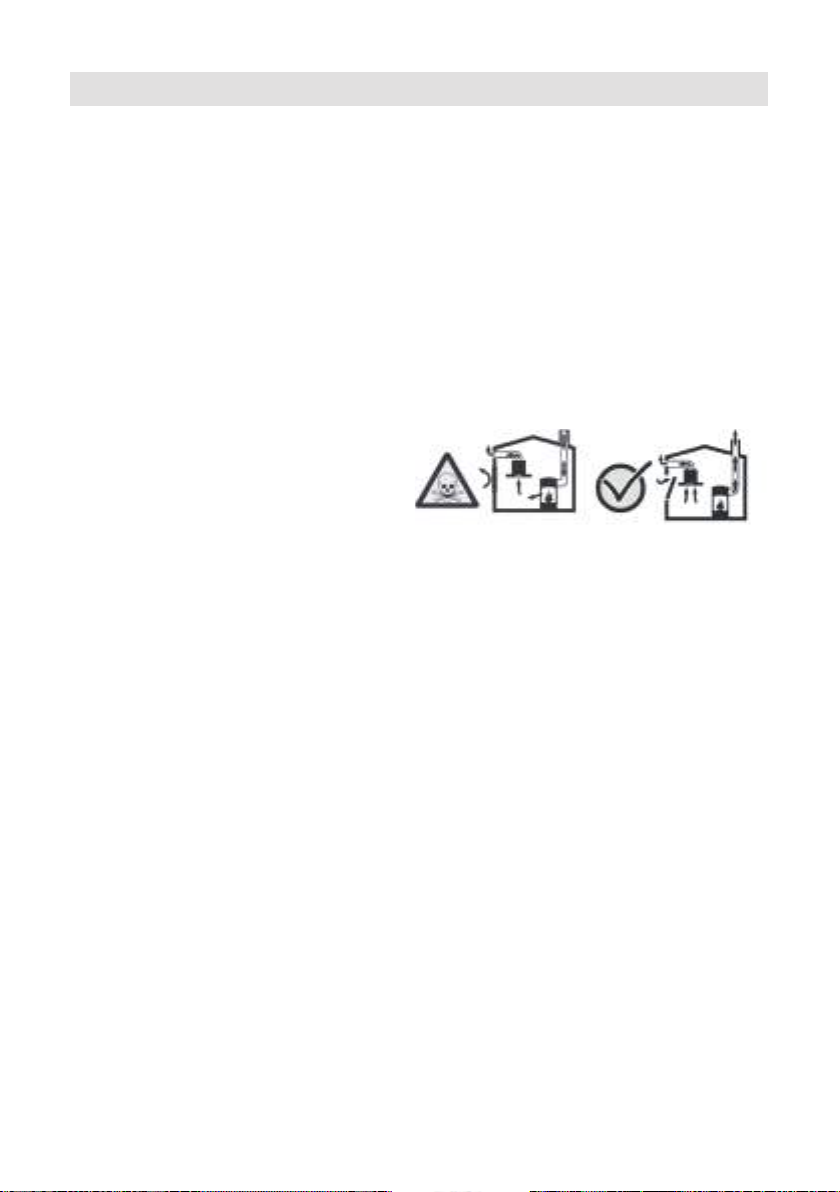
hood is operated simultaneously with other room air dependent fireplaces (e.g. wood-,
gas-, oil- or coal-fired appliances) in one room during exhaust air operation, deadly
combustion gases can be returned to the room through a negative pressure. The ope-
rator must therefore ensure an adequate supply of air at all times. The negative pres-
sure in the room must not exceed 4 Pa (0.04mbar). Do not exceed max. duct length of
5m with B-version.
Fireplace for solid fuels
The cooker hood may only be installed above a fireplace for solid fuels from which
there is a risk of fire (e.g. flying sparks) if the fireplace has a closed, non-removable
cover.
Installation
The device may only be connected by authorised specialists in compliance with all
relevant regulations of the power supply companies as well as the building regulations
of the federal states. Observe the corresponding instructions during installation! Da-
mage to the device must be reported immediately upon delivery. Damaged devices
may be installed. Defective parts must be replaced by original parts. Repairs may only
be carried out by authorised specialist personnel.
Air turbulence can occur at high levels with C recirculation air versions!
Before the cooker hood leaves our factory, it is subjected to a detailed functional test
by our quality control department before being shipped.
The pictures, drawings and models shown in the operating instructions may differ
from the model supplied or may contain options which are not included in the scope of
delivery.
We reserve the right to make technical changes!
Exhaust air duct (for exhaust air operation)
5
EN
1.SAFETY INSTRUCTIONS

- Fonda Professional Type: DFP83B120
DFP83C120
DFP83B140
DFP83C140
Dimensions: - 830 x 580 x 81 mm
Motor voltage: - 1N ~ 220-240 V 50/60 Hz
Integrated motor: - Airflow: free flow: 900 m³/h
- Power: 169 Watt
Cooktop: - Max Power:
- Voltage: 7,4 KW
1N ~ 220-240 V 50/60 Hz
2N ~ 380-415 V 50/60 Hz
Filter: - 1 condensation filter
- 1 grease filter
- 1 activated carbon filter (only in C - version)
Control element: - Touch interface (glass)
Connection pipe: - Naber 220x90mm
Weight: - ~27 KG (without motor)
DFP83___
Designation:
6
EN 2.TECHNICAL DATAANDCONNECTION VALUES

FONDA PROFESSIONAL B/C - Version
1
2
3
4
5
6
7
8
9
10
Fonda Professional cooking hob
Touch control panel
Air inlet glass, variably adjustable
Naber canal (fitting length)
Fan motor B/C version
Outlet nozzle in air direction
Nozzle plate for change of blowing direction
Suction silencer
Outlet silencer
Fan-cooking hob connection cable
Airflow
1
2
4
5
6
7
8
9
3
10
7
EN
3.PRODUCT DESCRIPTION

11
12
13
14
Activated carbon filters (C version only)
Grease filters
Water collector
Condensation filter
Installation sequence: 11-12-13-14-3
3
14
13
12
11
8
EN

- - -
Hob with extractor Fan motor Intake silencer
B/C - Version
Blow-out silencer
B/C - Version Safetyglass Cover sheet kit
Condensation filter with
water collector Grease filter Activated carbon filter
C- version only
10 x Sheet metal screws Naber duct Adhesive tape
PU foam tape
9
EN
4.MOUNTING ACCESSORIES-SCOPE OFDELIVERY

10
EN 5.DIMENSIONS
799
241
4
52
554
540/610
134
81
2545
81
148
540/610
554
Option 1 - Max depth of top 20 mm (DFP83_120)
Option 2 - Max depth of top 40 mm (DFP83_140)

11
EN
580
830
R3,5

! It is essential to insert the cover !
12
EN
Adjusting the nozzle extension
Min. (L= 40 mm) Normal (L= 70 mm) Max. (L= 100 mm)
543/612 50
45
89 495/565
477/547
445
120 77
115

Duct terminal
changeable
13
EN

Transport, unpacking, setting up
If the device is brought from a cold environment into the operating room, condensati-
on may occur. Please wait until the device has reached the correct temperature and is
absolutely dry before putting it into operation. The acclimatization time depends on
the temperature difference and the device as well as its construction. However, it
should be at least 12 hours.
Please wear protective gloves during installation to avoid the risk of injury. Before
mounting the hood, prepare the necessary tools.
For the installation of the hood, the customer must provide the prerequisites for a
smooth installation of the hood and cover kitchen appliances.
Prepare a suitable exhaust air duct, if necessary open false ceiling, partition walls,
kitchen block, create openings etc...
14
EN 6.ASSEMBLY PREPARATION

Flush mounting
Surface mounting
15
EN
7.FITTING REQUIREMENTS
SECTION A-A
AA
584
834
805
50 560 60> 15/40
5
R5,5
15/35
60>560
805
50

Safety instructions for the kitchen furniture fitter
Veneers, adhesives or plastic coverings of adjacent furniture must be temperature-
resistant (min. 75°C). If the veneers and coverings are not sufficiently temperature-
resistant, they may deform.
The use of solid wood wall end strips on the worktop behind the hob is permitted,
provided that the minimum distances are observed in accordance with the
installation sketches.
The minimum distances of the recess cut-outs to the rear according to the
installation sketch must be observed.
For installation directly next to a tall cabinet, a safety distance of at least 50 mm
must be maintained. The side surface of the tall cabinet must be covered with heat-
resistant material. For technical reasons, however, the distance should be at least
300 mm.
The packaging materials (plastic foils, polystyrene, nails, etc.) must be taken out of
the reach of children, as these parts represent possible sources of danger. Small
parts could be swallowed and foils pose a suffocation hazard.
Ventilation
The induction hob has a fan that automatically switches on and off. If the
temperature values of the electronics exceed a certain threshold, the fan starts at a
low speed. If the induction hob is used intensively, the fan switches to a higher
speed. If the electronics have cooled down sufficiently, the fan reduces its speed
and switches off again automatically.
The distance between the induction hob and kitchen furniture or built-in appliances
must be chosen so that sufficient ventilation of the induction is guaranteed.
To ventilate the hob
electronics, open the rear
wall of the base cabinet in
the area of the hob. The
front crossbar of the base
cabinet must be removed
over the entire width of
the hob.
In addition, an air gap of at
least 5 mm at the front
below the worktop is
mandatory.
EN
16

Installation, important notes!
- Excessive heat development from be-
low, e.g. from a baking oven without
cross-flow fan, should be avoided.
- If pyrolysis operation takes place at
built-in cookers, the induction hob
must not be used.
- When installing above a drawer, care
must be taken to ensure that no
sharp objects are stored in the dra-
wer. These could tilt on the underside
of the hob and block the drawer.
- If there is an intermediate bottom be-
low the hob, sufficient ventilation of
the hob inductors must be ensured.
- The cooktop must not be installed
above refrigerators, dishwashers,
washing machines or dryers.
- It must be ensured that no flammable,
easily flammable or heat deformable
objects are placed directly next to or
below the hob due to the risk of fire.
Hob gasket
Wood worktops must be sealed on the
cut surfaces.
Before installation, the enclosed cooktop
gasket must be inserted without gaps.
- It must be prevented that liquids can
penetrate between the edge of the hob
and the worktop or between the worktop
and the wall into any electrical appli-
ances installed underneath.
- If the hob is installed in an uneven
worktop, e.g. with a ceramic or similar
covering (tiles, etc.), the cooking surface
must be sealed against the worktop with
plastic sealing materials (e.g. Novasil®
or Ottoseal® ).
Note:
- If sealing adhesive is used for sealing
and fixing, a later, non-destructive re-
moval of the hob cannot be guaranteed.
Worktop cut-out
The cut-out in the worktop should be
made as accurately as possible with a
good, straight saw blade or a router.
The cut surfaces should then be sealed
to prevent moisture from penetrating.
The cut-out for the hob is made accord-
ing to the illustrations. The glass-
ceramic hob surface must be flat and
flush. Tensioning can cause the glass
plate to break. Check the seal of the
cooking surface for a perfect fit and
complete support.
Exhaust air - outlet opening
The cross-section of the wall boxes and
the cut-out in the plinth panels should at
least correspond to the exhaust air ope-
ning. There must be one or more air
outlet openings of at least 500cm² in
total. Shorten the height of the skirting
boards or insert corresponding ope-
nings.
> 500mm²
EN
17

WARNING AGAINST ELECTRICAL
ENERGY!
THERE IS DANGER TO LIFE!
There are voltage-carrying parts near
this symbol.
Covers marked with this symbol may
only be removed by a qualified electrici-
an.
- The electrical connection may only
be carried out by an authorised spe-
cialist!
- The statutory regulations and connec-
tion conditions of the local electrical
supply company must be observed in
full.
- When the device is connected, a de-
vice must be provided which makes it
possible to disconnect the device
from the mains with an opening width
of at least 3 mm all poles using a
contact. LS switches, fuses and
contactors are regarded as suitable
disconnecting devices. When
connecting and repairing the device,
disconnect it from the power supply
using one of these devices.
- The protective conductor must be long
enough so thatif the strain relief fails,
it will only be subjected to tensile
stress after the current-carrying
cores of the connecting cable.
- The excess cable length must be pul-
led out of the installation area below
the device.
- Please make sure that the mains vol-
tage is the same as on the namepla-
te.
- Complete protection against acciden-
tal contact must be ensured by instal-
lation.
- Attention: Incorrect connection can
lead to destruction of the power
electronics.
- The device is only approved for a fixed
connection. It must not be connected
with a shock-proof plug.
Connected loads
Mains voltage: 380-415 V 2N~, 50/60 Hz or
220-240 V 1N~ 50/60 Hz.
Nominal component voltage:
220-240V 50/60 Hz ( see instructions hob )
Connectingcableavailableatthefactory
- The hob is equipped with a tempera-
ture-resistant connection cable at the
factory.
- The mains connection is carried out
according to the connection diagram,
except the connection cable is al-
ready equipped with a plug.
- If the power cord of this unit is dama-
ged, it must be replaced with a speci-
al power cord. In order to avoid ha-
zards, this may only be done by the
manufacturer or his customer ser-
vice.
EN
18
8. INSTALLATIONPREREQUISITES -Electricalconnection
One phase connection
1N 220-240 V 50/60 Hz 5x1.5 mm²
BLACK
BROWN
BLUE
GRAY
GREEN/YELLOW
L1
N
Two phases connection
2N 380-415 V 50/60 Hz 5x1.5 mm²
BLACK
BROWN
BLUE
GRAY
GREEN/YELLOW
L1
N
L2
Table of contents
Languages:
Other Opera Cooker manuals
Popular Cooker manuals by other brands

Range Master
Range Master PROP90NGF User's guide & installation instructions

Range Master
Range Master ELS110DFF User's guide & installation instructions

Bosch
Bosch HSG738257M instruction manual

Zanussi
Zanussi ZCG661 user manual

Elite Gourmet
Elite Gourmet MST-250XW instruction manual

Petromax
Petromax Atago user manual

Zanussi
Zanussi ZCI66250BA user manual

Siemens
Siemens HL9S7W340 user manual

Bosch
Bosch HCE644123R instruction manual

Moffat
Moffat GSC 5062 Operating & installation instructions

Siemens
Siemens HE517AB 1 Series User manual and installation instructions

RM Gastro
RM Gastro SPBT-780-21 GE Instructions for installation and use