Opera Q9 User manual

MADE IN ITALY
design & production
Q9 pellet stoves UseR MANUAl
eNGlIsH/INGlese

2

index
3
ENGLISH
We thank you for having chosen our company; our product is a great heating solution developed from the
most advanced technology with top quality machining and modern design, aimed at making you enjoy
the fantastic sensation that the heat of a ame gives, in complete safety.
Opera
Safety deviceS.............................................................................................................................................................................................. 4
RefeRence StandaRdS ................................................................................................................................................................................ 4
General........................................................................................................................................................................................................................................................5
inStaLLatiOn.................................................................................................................................................................................................. 6
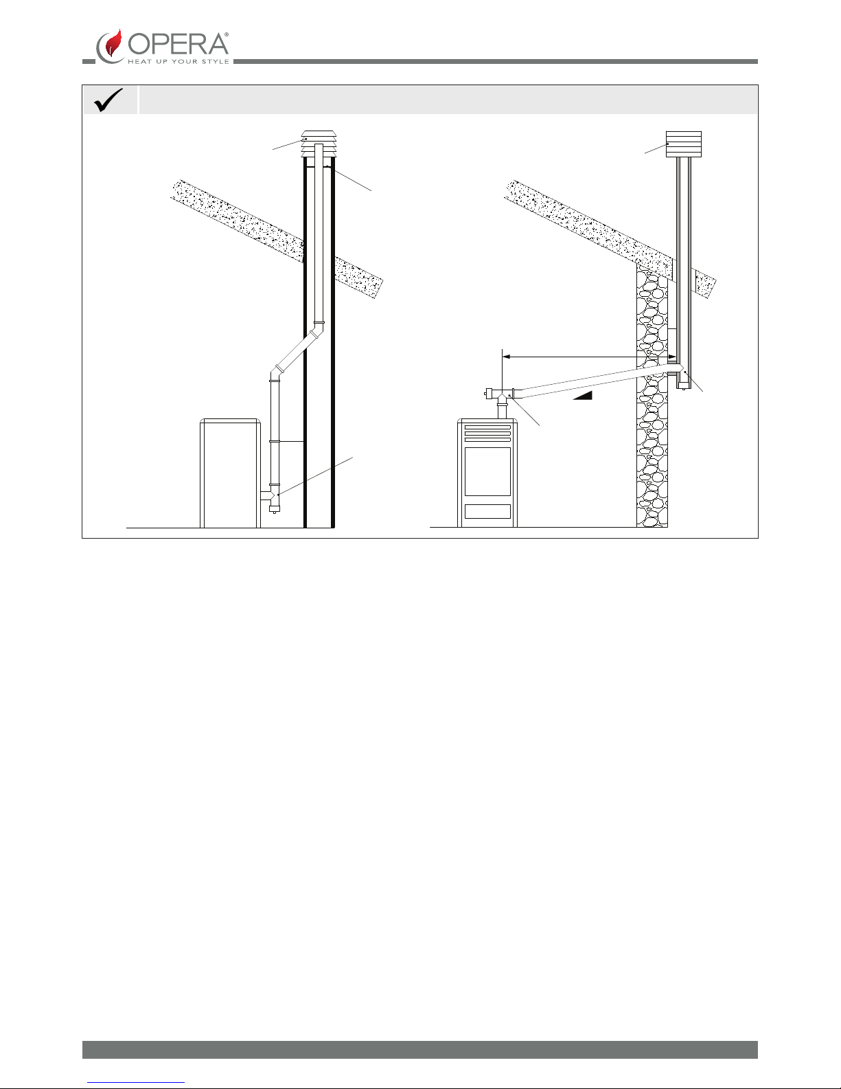
fumeS exhauSt SyStem............................................................................................................................................................................... 7
General requirements......................................................................................................................................................................................................................7
smoke duct ...............................................................................................................................................................................................................................................8
chimney......................................................................................................................................................................................................................................................10
chimney caps .........................................................................................................................................................................................................................................10
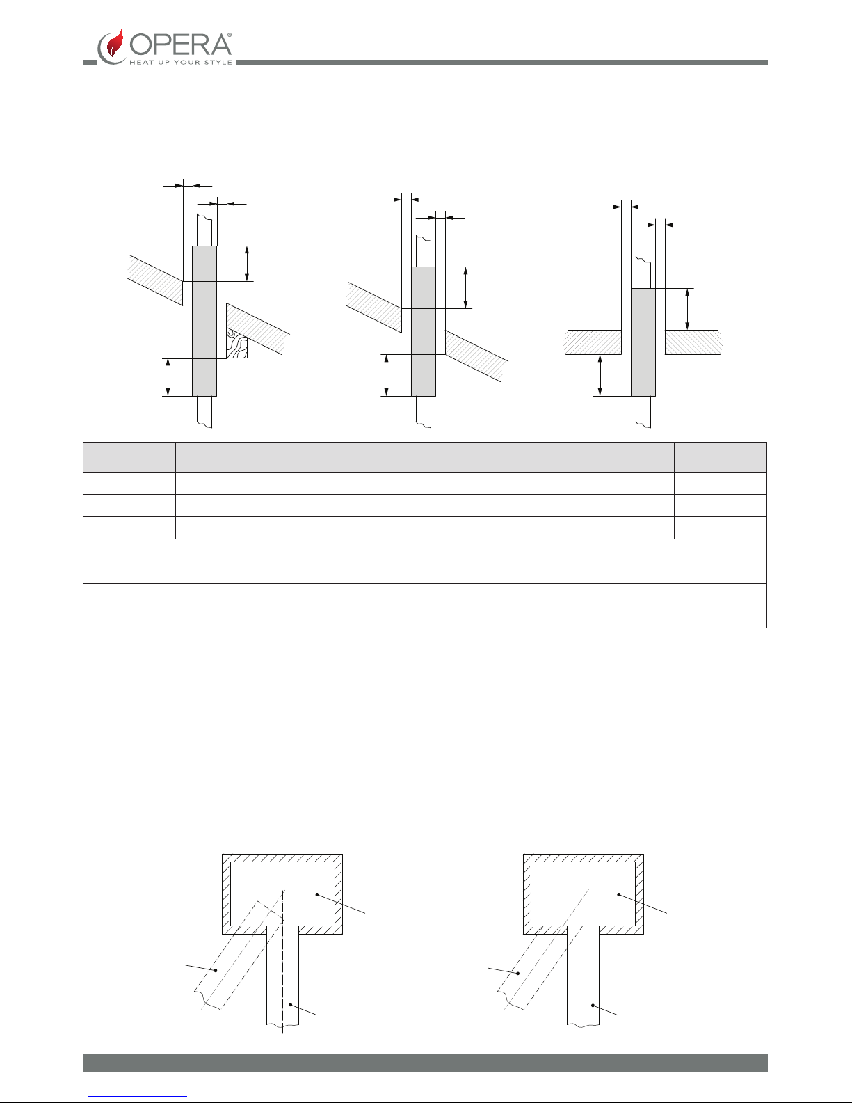
combustion products outlet quota ..................................................................................................................................................................................11
Fumes eXhaust system product requirements.............................................................................................................................................................11
technical installation documentation ...........................................................................................................................................................................12
WaRningS...................................................................................................................................................................................................... 13
Safety............................................................................................................................................................................................................ 13
ROutine maintenance.............................................................................................................................................................................. 13
identificatiOn Of the Q9 ducted inSeRt cOmpOnentS.................................................................................................................. 14
geneRaL WaRningS fOR Q9 inStaLLatiOn............................................................................................................................................ 16
meaSuRementS neceSSaRy fOR cORRect inStaLLatiOn.................................................................................................................. 18
Q9 ducted inStaLLatiOn .......................................................................................................................................................................... 19
assembly with slidinG base..........................................................................................................................................................................................................20
positioninG the appliance in a pre-eXistinG chimney ...............................................................................................................................................22
assembly procedure with pedestal.......................................................................................................................................................................................23
positioninG appliance on the support pedestal .........................................................................................................................................................26
ducting ........................................................................................................................................................................................................ 27
peLLetS and feeding ................................................................................................................................................................................. 28
Q9 ducted technicaL data...................................................................................................................................................................... 29
OpeRatOR inteRface .................................................................................................................................................................................. 30
conFiGuration with the appliance........................................................................................................................................................................................31
list oF quick commands ...............................................................................................................................................................................................................32
preliminary operations.................................................................................................................................................................................................................32
switchinG the appliance on........................................................................................................................................................................................................32
manual mode ........................................................................................................................................................................................................................................34
chrono mode........................................................................................................................................................................................................................................34
switchinG the appliance oFF......................................................................................................................................................................................................36
uSeR menu..................................................................................................................................................................................................... 36
preloadinG..............................................................................................................................................................................................................................................36
system status ........................................................................................................................................................................................................................................37
pellet settinG: .....................................................................................................................................................................................................................................37
General settinGs ................................................................................................................................................................................................................................38
time settinG ............................................................................................................................................................................................................................................38
display oFF...............................................................................................................................................................................................................................................38
stand-by....................................................................................................................................................................................................................................................39
use remote probe................................................................................................................................................................................................................................39
lanGuaGe settinG ..............................................................................................................................................................................................................................39
loGs..............................................................................................................................................................................................................................................................40
serVice ........................................................................................................................................................................................................................................................40
buZZer on/ oFF......................................................................................................................................................................................................................................40
aLaRmS .......................................................................................................................................................................................................... 41
recoVery ...................................................................................................................................................................................................................................................41
hand-heLd teRminaL bReakage ............................................................................................................................................................ 42
appendiX "a" automatic mode.....................................................................................................................................................................................................43
maintenance............................................................................................................................................................................................... 44
notes on maintenance...................................................................................................................................................................................................................44
daily cleaninG by the user...........................................................................................................................................................................................................44
suGGestions For proper use.......................................................................................................................................................................................................47

4
ENGLISH
SAFETY DEVICES
SAFETY DEVICES
KEY: * = PRESENT, = NOT PRESENT
STOVES
Circuit board: it intervenes directly sending the product
into alarm conditions until it has fully cooled down, in
the event of: fumes motor breakage, pellet feed motor
breakage, black out (if above 10 seconds), failed ignition
*
Door micro switch: With the door open, the operation of
the burn pot cleaning system is blocked -
Electronic pressure switch: in the event of inadequate
depression, it sends the machine in alarm conditions *
F 2.5 A 250 V fuse (stoves): protects the machine from
violent current surges *
85°C calibrated mechanical bulb with manual rearm:
intervenes by blocking fuel feed whenever the pellet tank
t° reaches the limit of 85°C. Rearm must be performed
by qualied sta and/or the manufacturer's technical
after-sales assistance.
*
Pellet tank temperature control probe: if the tank over-
heats, the machine automatically modulates to return to
normal temperature values (* in the applicable models)
*
Mechanical air pressure switch: blocks the pellet in the
event of insucient depression (in the relevant models) *
REFERENCE STANDARDS
The installation must be in compliance with:
UNI 10683 (2012) heat generators fed with wood and
other solid fuels: installation.
The chimneys must be in compliance with:
UNI EN 13063-1 and UNI EN 13063-2, UNI EN 1457, UNI
EN 1806 in the event of non-metallic chimneys:
EN 13384-1 (13384) chimneys.Thermal and uid dynamic
calculation methods.
UNI EN 1443 (2005) chimneys: general requirements.
UNI EN 1457 (2012) chimneys: clay/ceramic ue liners.
UNI/TS 11278 (2008) Metal - chimneys/ue liners/ue
ducts.
UNI 7129 point 4.3.3 Fire Brigade provisions, local rules
and regulations.
NATIONAL, REGIONAL, PROVINCIAL AND TOWN
COUNCIL REGULATIONS
One must also bear in mind all laws and national, regional,
provincial and town council Standards present in the country
in which the appliance has been installed.
TERMS AND DEFINITIONS
Aeration: Air renewal is required both for the disposal of
the combustion products, and to prevent mixtures with a
hazardous content of non-combusted gases.
Closed hearth appliance: Appliance designed for operation
with closed combustion chamber.
Forced draught appliance: Appliance with ventilation in the
fumes circuit and combustion with fumes ow at a positive
pressure with respect to the environment.
Chimney: Structure consisting in one or several walls
containing one or several outow airways.
The purpose of this predominantly vertical element is to expel
the combustion products at a convenient height from the
ground.
Smoke duct: Component or components that connect the
outlet of the heat generator to the chimney.
Chimney cap: Device that placed on the chimney outlet
allows the dispersion of the combustion products even in
presence of adverse weather conditions.
Condensation: Liquid products which form when the fumes
temperature is lower or equal to the water dew point.
Ducting pipe: Pipe made up of one or several predominantly
vertical elements, specically suitable for collecting and
expelling the fumes, as well as to withstand the relative
components and any condensate over time,
suitable to be installed in a chimney, existing or new technical
compartment, even in new buildings.
Sealed installation: Installation of an appliance with sealed
operation, so that all the air required for combustion is taken
from outside.
Maintenance: Set of procedures required to ensure and
maintain safety and functionality over time and maintain the
eciency of the system within the prescribed parameters.
Chimney system: Chimney installed using a combination
of compatible components, manufactured or specied by a
sole manufacturer whose product liability covers the entire
chimney.
Fumes exhaust system: Flue gas exhaust system,
independent from the appliance made up of a smoke duct,
chimney or individual ue and chimney cap.
Radiation area: Area immediately in front of the hearth in
which the radiant heat caused by combustion is diused.
Reux area: Area beyond the extrados of the roof in which
overpressure or depressions occur, which may aect the
proper discharge of the combustion products.
| ENGLISH

5
ENGLISH
| ENGLISH
FUNCTIONAL OPERATIONS DIAGRAM
State of the art installation and proper system operation include a series of activities:
1. Preliminary activities:
verication of the suitability of the installation site,
verication of the suitability of the fumes exhaust system,
verication of the suitability of the outside air inlets;
2. Installation:
implementation of ventilation and connection to the outer air inlets,
implementation and connection to the fumes exhaust system,
assembly and installation,
electric and hydraulic connections,
installation of insulation,
ignition and operation test,
installation of nishings and coverings;
3. Issue of complementary documentation;
4. Inspection and maintenance.
Other actions may be required in relation to specic requests of the competent authority.
PRELIMINARY ACTIVITIES
GENERAL
Verication of compatibility of the system, of any restrictions required by local administrative regulations, special or conventional
requirements resulting from condominium regulations, constraints, laws or administration deeds must precede any other
assembly or installation operation.
One must especially verify the suitability:
of the installation premises, of the appliances already installed in the installation premises and in the adjacent and
adjoining premises, also powered by dierent fuels, with particular reference to non-compliant installations.
of the fumes exhaust system
of the outside air inlets
SUITABILITY OF THE FUMES EXHAUST SYSTEM
Installation must be preceded by a compatibility test between the appliance and the fumes exhaust system, by verifying:
the existence of documentation relating to the system;
existence and content of the chimney plaque;
suitability of the internal section of the chimney;
absence of obstructions all along the chimney;
predominantly vertical height and development of the chimney;
existence and suitability of the chimney cap;
distance of the outside wall of the chimney and of the smoke duct from
combustible materials;
chimney type and material;
absence of other chimney connections.

BCA
S
6
ENGLISH
| ENGLISH
INSTALLATION
Installation in premises with re hazards is forbidden. Installation in residential premises (except for sealed operation appliances)
is also forbidden:
in which there are liquid fuel-operated appliances with continuous or intermittent operation, which draw the combustion
air in the room in which they are installed, or
in which there are type B gas appliances intended for room heating, with or without production of domestic hot water and
in adjacent and adjoining premises, or
in which, in any case, the depression measured during installation between the internal and external environment is
greater than 4 Pa
Installations in bathrooms, bedrooms and studio ats
Installation in bathrooms, bedrooms and studio ats is only allowed for sealed or closed hearth appliances with ducted
combustion air taken from the outside.
Installation premises requirements
The support surfaces and/or points must have a suitable load-bearing capacity to support the weight of the appliance, of the
accessories and coatings.
The adjacent, side and rear walls and the supporting surface must be made of non-combustible material according to the table
REFERENCES INFLAMMABLE OBJECTS NONINFLAMMABLE OBJECTS
A 200 mm 100 mm
B 1500 mm 750 mm
C 200 mm 100 mm
In any case the temperature of the adjacent combustible materials must not reach a temperature equal to or greater than the
room temperature increased by 65°C.
The minimum volume of the premises in which to install the appliance must be greater than 15 m³.
Air inlet
S= oor protection
Flue
Inspection
gure 1 gure 2

7
ENGLISH
| ENGLISH
VENTILATION AND AERATION OF THE INSTALLATION PREMISES
Ventilation is deemed sucient when the room is equipped with air inlets according to the table:
Air inlet
See gure 2
Appliance categories Reference standard
Percentage of the
net opening section with
respect to the appliance fumes
outlet section
Minimum net opening value of
the ventilation duct
Pellet stoves UNI EN 14785 - 80 cm²
In any case ventilation is deemed sucient when the pressure dierence between the external and internal environment is
equal to or less than 4 Pa.
In the presence of type B gas appliances with intermittent operation not intended for heating, they must have their own aeration
and/or ventilation opening. The air inlets must meet the following requirements:
they must be protected with grids, metal mesh, etc., but without reducing the net useful section;
they must be made so as to make the maintenance operations possible;
positioned so that they cannot be obstructed;
The air ow can also be obtained from a room adjacent to that of installation (indirect aeration and ventilation), as long as the
ow takes place freely through permanent openings communicating with the outside.
The adjacent room cannot be used as a garage, warehouse of combustible material or for any other activity with a re hazard,
bathroom, bedroom or common room of the building.
FUMES EXHAUST SYSTEM
GENERAL REQUIREMENTS
Each appliance must be connected to a suitable fumes exhaust system and ensure adequate dispersion of the combustion
products into the atmosphere. The combustion products must discharged above the roof. Direct discharge from the wall or
towards closed spaces is forbidden, even with clear skies.
In particular, it is forbidden to use exible and extendible metal pipes.
The chimney should only receive the exhaust of the smoke duct connected to the appliance; collective ues or conveying
exhausts from hoods above cooking appliances of any kind, or exhausts from other generators into the chimney itself or smoke
duct are not allowed.
The smoke duct and the chimney must be connected with a continuity solution, in order to prevent the chimney from resting
on the appliance.
It is forbidden to have other air supply channels and pipes for plant engineering transit inside the fumes exhaust systems,
especially if over-sized.
The components of the fumes exhaust system must be chosen in relation to the type
of appliance to be installed in compliance with:
in the event of metal chimneys, UNI/ TS 11278, with particular attention to what is stated in the specication;
in the event of non-metallic chimneys: UNI EN 13063-1 and UNI EN 13063-2, UNI EN 1457, .-UNI EN 1806; considering
especially:
temperature class;
pressure class (fumes seal) at least equal to the seal required for the appliance;
moisture resistance (resistance to condensation);
class or level of corrosion and specication of the materials constituting the inner wall in contact with the fumes.
soot re resistance class;
minimum distance from combustible materials
The installer of the fumes exhaust system, once the installation is complete and the relevant checks and inspections have been
made, must x the chimney plaque supplied by the manufacturer with the product in a visible manner, near the replace, and
which must be completed with the following information:

a
a
b.1
b
a
aa
a
b.1
b.1
b b
OK OK
8
ENGLISH
| ENGLISH
SMOKE DUCT
General requirements
The smoke ducts must be installed in compliance with the following general requirements:
they must be insulated if they cross through rooms that are not to be heated or outside the building;
they must not cross rooms in which the installation of combustion appliances is forbidden, nor in other premises
compartmentalised against re or with a re hazard, nor in rooms and/or areas that cannot be inspected;
they must be installed so as to allow normal thermal expansion;
they must be tted to the opening of the chimney without protruding inwards;
the use of exible metal pipes to connect the appliance to the chimney is not allowed;
nominal diameter;
distance from combustible materials, indicated in millimetres, followed by the arrow and ame symbol;
installer data and date of installation.
Every time one must cross combustible materials, the following indications must be complied with:
SYMBOL DESCRIPTION QUOTAMM
bMinimum distance of combustible materials from the intrados of the framework/oor/wall 500
b.1 Minimum distance of combustible materials from the extrados of the framework/oor 500
a Minimum distance from combustible materials dened by the manufacturer G(xxx)
The single wall pipes are indicated in white.
The insulated double wall chimney systems are indicated in grey.
One can disregard the quota only in the event of using an appropriate heat protection screen (for example: wall plate) to
protect the intrados of the framework/oor
Chimney Chimney
Incorrect Correct

9
ENGLISH
counter-slope sections are not allowed;
the smoke ducts must have, along their entire length, a diameter that is no less than that of the attachment of the appliance
exhaust pipe; any section changes are allowed only on the inlet to the chimney;
they must be installed so as to limit the formation of condensation and prevent their release from the joints;
they must be positioned at a distance no less than that indicated in the product specications from combustible materials;
the smoke channel/duct must allow to collect the soot and to be cleaned using a swab and inspected after being
disassembled, or through inspection openings when not accessible from inside the appliance.
ADDITIONAL REQUIREMENTS FOR APPLIANCES FITTED WITH AN ELECTRIC FAN FOR FUMES EXPULSION
For the heat generator appliances equipped with electric fan for expelling fumes, the instructions below must be followed:
The horizontal sections must have a minimum upward slope of 3%
The length of the horizontal section must be minimal and, in any case, no longer than 3 metres
The number of direction changes including the one due to the use of the "T" element must not be more than 4.
Ash deposited in
the 90° bend
Ash deposited in
the 90° bend
Installation with internal ue
Protection from
rain and wind
Protection from
rain and wind
Insulated ue
Insulated
condensation-
proof "T" tting
with inspection
plug
Condensation-proof
"T" tting with
inspection plug
Insulated ue
Installation with internal - external
ue
| ENGLISH
IT IS NOT RECOMMENDED TO INSTALL A 90° BEND AS THE FIRST INITIAL PART, SINCE THE ASH WOULD BLOCK THE
PASSAGE OF THE FUMES IN A SHORT TIME, CAUSING PROBLEMSTOTHE STOVE DRAUGHT. SEE FIGURES BELOW:
EXAMPLES OF CORRECT CONNECTION TO THE CHIMNEY

3 - 5%
Max 3 mt
10
ENGLISH
It is mandatory to use airtight pipes.
CHIMNEY
In addition to the general requirements, the chimneys for releasing combustion products into the atmosphere must:
operate under negative pressure (operation under positive pressure is not allowed);
have a preferably circular internal section; square or rectangular sections must have rounded corners with a radius of no
less than 20 mm (hydraulically equivalent sections may be used, as long as the ratio between the longer side and the shorter
side of the rectangle, which circumscribes the section, is in any case no greater than 1.5);
be designed for fumes be designed for fumes expulsion;
be predominantly vertical and have no narrowing along their entire length;
have no more than two direction changes with a slope angle no greater than 45°;
be tted with, in the event of operating in damp conditions, a device for reux drainage (condensation, rainwater);
Ducted system
A ducted system can be installed with one or more ducts, operating only with negative pressure with respect to the environment.
The exible hose compliant with UNI EN 1856-2, with T400-G characteristics, meets the requirements.
CHIMNEY CAPS
The chimney caps must meet the following requirements:
they must have a useful outlet section no less than double of that of the chimney/ducted system on which it is installed;
they must be adapted in order to prevent the penetration of rain and snow in the chimney/ducted system;
they must be built so that, in the event of winds coming from all directions and from any angle, the expulsion of combustion
products is in any case ensured;
they must be free from mechanical intake aids.
"T" tting with
inspection
plug
Steel plate,
airtight
Insulated "T"
tting with
inspection plug
Protection from rain
and wind
Protection from rain
and wind
"T" tting with
inspection plug
| ENGLISH
EXAMPLES OF CORRECT CONNECTION TO THE CHIMNEY

90°
c
a
ß
11
ENGLISH
The outlet of a chimney/ducted system must not be near obstacles that may create turbulence areas and/or prevent proper
expulsion of combustion products and maintenance operations to be carried out on the roof.
Verify the presence of other chimney caps or skylights and dormers.
FUMES EXHAUST SYSTEM PRODUCT REQUIREMENTS
Temperature class
In the event of a pellet appliance, temperature classes below T200 are not allowed.
Soot re resistance class
The fumes exhaust system interlocked with appliances supplied by solid fuels require soot re resistance, and the specication
must be indicated by the letter G followed by the distance from combustible materials in millimeters (XX) (in compliance with
UNI EN 1443) .
In the event of pellet appliances, the fumes exhaust systems must be airtight; if double designation elements are used (G and
O, with or without seal elastomer) for connecting the appliance to the chimney, one must comply with the minimum distance
XX in millimeters, indicated for designation G; in the event of re due to soot, one must ensure the restoration of the initial
conditions (by replacing the gaskets and damaged items and cleaning those remaining in use).
Ignition tests
Operation of the appliance must be veried with an ignition test, i.e.:
for mechanical feed appliances, one must complete the ignition test, verify proper operation for at least the next 15
minutes and adjust the switch-o;
For appliances installed in a hot water heating system (closed replaces, thermo-stoves), testing must also extend to the entire
hydraulic circuit.
COMBUSTION PRODUCTS OUTLET QUOTA
The outlet quota is determined by measuring the minimum height between the roof covering and the lower point of the fumes
expulsion section into the atmosphere; this quota must be outside the reux area and at an adequate distance from obstacles
which hinder or make the expulsion of the combustion products dicult or from openings or accessible areas.
Reux area
The outlet quota must be outside the reux area calculated according to the indications below.
Near the ridge one considers the lowest between the two.
Buer area for outlet quota
Clear area for outlet quota above the roof slope ( ß>10°)
REFERENCE DESCRIPTION CLEAR AREA MM
c Distance measured at 90° from the roof surface 1300
a Height above the ridge of the roof 500
| ENGLISH

12
ENGLISH
Coverings and nishings
The coverings and nishings must only be applied after having veried the proper operation of the appliance according to the
indicated modalities
TECHNICAL INSTALLATION DOCUMENTATION
When installation is complete, the installer must provide the owner or person acting for him, according to the legislation in
force, with the declaration of conformity, supplied with:
1) the use and maintenance manual of the appliance and of the system components (such as for example, the smoke ducts,
chimney, etc.);
2) photocopy or photograph of the chimney plaque;
3) system booklet (where applicable).
The installer must ask to be issued with a receipt stating that the documentation has been provided, and must keep it with a copy of
the technical documentation relating to the installation.
Installation performed by several parties
If the individual installation steps are carried out by dierent parties, each must document the work carried out for the customer
and the for the operator working on the next step.
INSPECTION AND MAINTENANCE
Frequency of operations
Maintenance of the heating system and of the appliance must be carried out on a regular basis according to the table below:
TYPE OF APPLIANCE INSTALLED <15kW (15- 35) kW
Pellet operated appliance 1 year 1 year
Water operated appliances
(closed replaces, thermo-stoves, thermo-kitchens) 1 year 1 year
Boilers 1 year 1 year
Fumes exhaust system 4 t of fuel used 4 t of fuel used
For further details refer to the "cleaning and maintenance" chapter.
Inspection and maintenance report
At the end of the inspection and/or maintenance operations, a report must be issued and released to the owner, or person
acting for him, who must conrm its receipt in writing. The report must indicate the situations encountered, the action taken,
any components replaced or installed and any comments, recommendations and requirements.
The report must be kept with the relative documentation.
In the inspection and maintenance report one must mention:
anomalies detected that cannot be removed, which pose a risk to the safety of the user or serious damage to building;
components that have been tampered with.
If anomalies as per above were detected, the owner, or person acting for him, must be warned in writing, in the maintenance
report, to refrain from using the system until the safety conditions have been fully restored.
The inspection and maintenance report must include the main information of the technician or company who performed the
inspection and/or maintenance operations, with their contact details, date of intervention and the signature of the operator.
| ENGLISH

13
ENGLISH
WARNINGS
This instructions manual is an integral part of the product: make sure that it always accompanies the appliance, even if
transferred to another owner or user, or if transferred to another place. If it is damaged or lost, request another copy from the
area technician. This product is intended for the use for which it has been expressly designed. The manufacturer is exempt from
any liability, contractual and extracontractual, for injury/damage caused to persons/animals and objects, due to installation,
adjustment and maintenance errors and improper use. Installation must be performed by qualied sta, which assumes
complete responsibility for the denitive installation and consequent good functioning of the product installed. One
must also bear in mind all laws and national, regional, provincial and town council Standards present in the country in
which the appliance has been installed.
Dal Zotto cannot be held responsible for the failure to comply with such precautions.
After removing the packaging, ensure that the content is intact and complete. Otherwise, contact the dealer where the appliance
was purchased.
All electric components that make up the product must be replaced with original spare parts exclusively by an authorised after-
sales centre, thus guaranteeing correct functioning.
SAFETY
The stove must not be used by persons (including children) with reduced physical, sensory and mental capacities or who
are unskilled persons, unless they are supervised and trained regarding use of the appliance by a person responsible for their
safety.
Children must be checked to ensure that they do not play with the appliance.
Do not touch the stove when you are barefoot or when parts of the body are wet or damp.
The safety and adjustment devices must not be modied without the authorisation or indications of the manufacturer.
Do not pull, disconnect, twist electric cables leaving the stove, even if disconnected from the electric power supply mains.
It is advised to position the power supply cable so that it does not come into contact with hot parts of the appliance.
The power supply plug must be accessible after installation.
Do not close or reduce the dimensions of the airing vents in the place of installation. The airing vents are essential for
correct combustion.
Do not leave the packaging elements within reach of children or unassisted disabled persons.
The hearth door must always be closed during normal functioning of the product.
When the appliance is functioning and hot to the touch, especially all external surfaces, attention must be paid
Check for the presence of any obstructions before switching the appliance on following a prolonged standstill period.
The stove has been designed to function in any climatic condition (even critical). In particularly adverse conditions (strong
wind, freezing) safety systems may intervene that switch the stove o. If this occurs, contact the technical after-sales service
and always disable the safety system.
If the ue should catch re, be equipped with suitable systems for suocating the ames or request help from the re
service.
This appliance must not be used to burn waste.
Do not use any inammable liquids for ignition
During the lling phase do not allow the bag of pellets to come into contact with the product
The majolicas are top quality artisan products and as such can have micro-dots, crackles and chromatic imperfections.
These features highlight their valuable nature. Due to their dierent dilation coecient, enamel and majolica produce
crackling,. which demonstrate their eective authenticity. To clean the majolicas, it is recommended to use a soft, dry cloth. If
a detergent or liquid is used, the latter could penetrate inside the crackles, highlighting the same.
ROUTINE MAINTENANCE
Based on the Decree 22 January 2008 n°37 art.2, routine maintenance means interventions aimed at reducing degradation from
normal use, as well as dealing with accidental events entailing the need of rst interventions, which however do not modify the
structure of the system upon which one is intervening or its intended use according to the prescriptions foreseen by technical
standards in force and by the manufacturer's use and maintenance booklet.

14
ENGLISH
IDENTIFICATION OF THE Q9 DUCTED INSERT COMPONENTS
The Q9 DUCTED stove/insert is made up from the parts indicated in Figure 1
Figure 1 Parts that make up the stove/insert - mod. Q9 DUCTED
PARTS LIST
ELEMENT QUANTITY DESCRIPTION
1 1 Ducted air conveyor box
2 1 Smoke outlet conveyor box
3 1 Chimney insert door
4 1 Primary air box
5 1 Upper plate
6 1 Primary air tube
7 1 Smoke exhaust outlet pipe
8 1 Pellet tank
9 2 Side protective frame
10 1 Upper protective frame

15
ENGLISH
The protective frame unit is supplied with the insert, but disassembled from the same, therefore the insert must be assembled
in the installation phase, after the frame has been pre-assembled (see Figure 2).
Figure 2 Parts that make up the protective frame - mod. Q9 DUCTED
PARTS LIST
ELEMENT DESCRIPTION
1 Upper protection
2 Side protection
3 Self-threading screw
4 Boiler/protection anchorage bracket
Assembly of the protection frame on insert
PARTS LIST
ELEMENT DESCRIPTION
1 Side protection
2 Upper protection
3 Side protection
4 Protection anchorage bracket
5 Self-threading screw 4.2x10 mm

MIN 10cm MIN 10cm
MIN 10cm
16
ENGLISH
GENERAL WARNINGS FOR Q9 INSTALLATION
The stove/insert must be installed on a levelled surface that can support its weight.
The minimum space to be left with respect to the rear walls is 10-15 cm.
Only use stainless or glazed steel pipes with leak-tight gasket. No exible hoses of any type are allowed.
Only use materials that resist temperatures over 300°C to x the pipes.
The safety distances with respect to inammable parts are minimum 1.5 mt. from the front of the stove/insert and 10/15
cm with respect to the other walls (min 5 cm - see gure below).
Minimum distance requested of 5 cm on all sides
Anti-wind cap
Inspection
Smoke outlet

17
ENGLISH
Q9 insert clearance
Open Q9 insert clearance

18
ENGLISH
MEASUREMENTS NECESSARY FOR CORRECT INSTALLATION
Lower part of the chimney vent: minimum opening 500 cm²;
Upper part of the chimney vent: minimum opening 550 cm².
In front view, 5 cm of free volume must be guaranteed on the 3 LH, RH and upper sides.
For aesthetic reasons, these areas are masked via:
Frames (protection) provided along with the insert
Q-Vision aesthetic frame provided on request (dierent dimensional and aesthetic variants) for ad hoc installation (e.g. on
the wall made-to-measure in plasterboard).
Stove/insert vent opening
Frame
Hot air outlet
Hot air outlet
Hot air outlet
Hot air outlet
Frame
Hot air outlet
Hot air outlet Cold air inlet
Cold air
inlet
Hot air outlet

DE
ABC
19
ENGLISH
Q9 DUCTED INSTALLATION
The insert is provided on an iron sliding base, which allows it to be installed in a pre-existing chimney.
This sliding base allows to extract the insert easily both for loading the pellets inside the tank and for any maintenance or end of
season cleaning. If there is not an existing chimney, one can be built using the insert-holder pedestal (optional kit); in fact, the
latter xes the insert to the ground.
Moreover, n°.3 extension frames are provided with the insert (6 cm) to allow the hot air that forms inside to escape and allow
the chimney insert to be ventilated.
Description of components:
Sliding base
Track
Smoke exhaust duct
Primary air intake duct
Current socket plug
Frame
Ducted air duct
ATTENTION
BEFORE PROCEEDING WITH INSTALLATION, THE INSERT MUST BE CONFIGURED ON THE BASIS OF ENVISIONED
USE:
NON DUCTED (frontal hot air only)
DUCTED (possibility of diverting hot air into other rooms)
- If a ducted insert is used, remove the ducting pipe cap (see gure below: A,B) and the ducting block plate (see gure
below: C).
- If a non ducted insert is used, remove the front air guard (see gure below: D,E).
ACTIVATE THE LEVER FOR THE REAR AIR DUCTED ONLY IF THE RELATIVE TUBES HAVE BEEN INSTALLED BY
QUALIFIED STAFF FOR THE DUCTING IF HOT AIR.

AB
20
ENGLISH
Smoke exhaust outlet
Inlet box
primary air
Slot for xing
base
Ducted air box outlet
Figure 3
ASSEMBLY WITH SLIDING BASE
Take the sliding base and position it in the existing chimney. Using a piece of chalk or pen, mark the base blocking holes on the
surface of the chimney. Make holes for the 8 mm steel expansion plugs.
Make a 60 mm hole in correspondence with the air vent.
ATTENTION
The air vent must be made outside the chimney because it must not take in overheated air.
Envision an air vent in the rear of the insert in a way that the plug is accessible once installation has been carried out.
Fix the base via the locking screws. Create the connection of the smoke exhaust and the vent respecting the points described
previously.
Lift the insert via the relative handles on the sides (see Figure below A), tilt it in a way that the wheels insert inside the relative
tracks, slide it until the smoke auger coupling is completely inserted into the smoke conveyor box.
Table of contents
Other Opera Stove manuals
Popular Stove manuals by other brands

Flame King
Flame King VT-505 Care, use and safety instructions

Superior
Superior GIOIA Instructions for installation, use and maintenance

Defy
Defy Thermofan 731 MF owner's manual

SCAN
SCAN 5002 Series Assembly and instruction manual

Regency
Regency Classic C34 Brochure & specs

Coleman
Coleman 5442 Series Instructions for use

Palazzetti
Palazzetti ECOFIRE HOTTY Instructions for use and maintenance

Dean Forge
Dean Forge Dartmoor Baker 8 operating instructions

Olsberg
Olsberg Tenorio PowerSystem Compact Instruction

Ravelli
Ravelli HRV 100 Globe brochure

Wonderfire
Wonderfire quattro 811 Installation and operating guide

hergom
hergom C-14 Installation, use and maintenance instructions