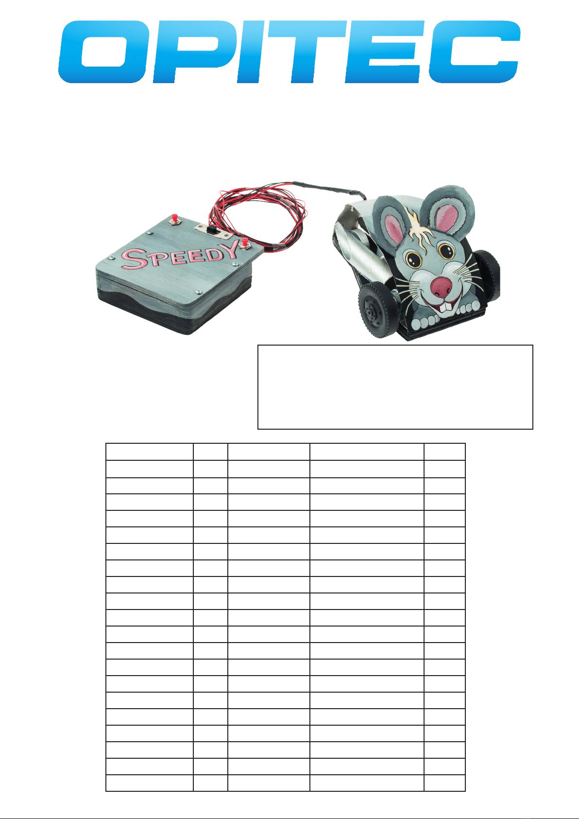
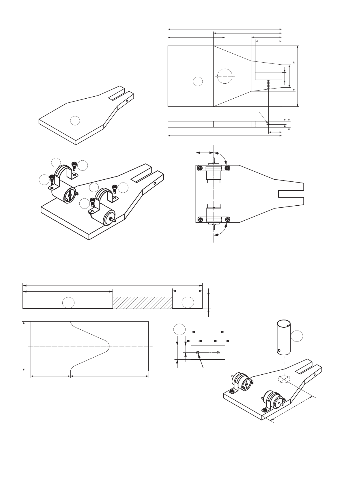
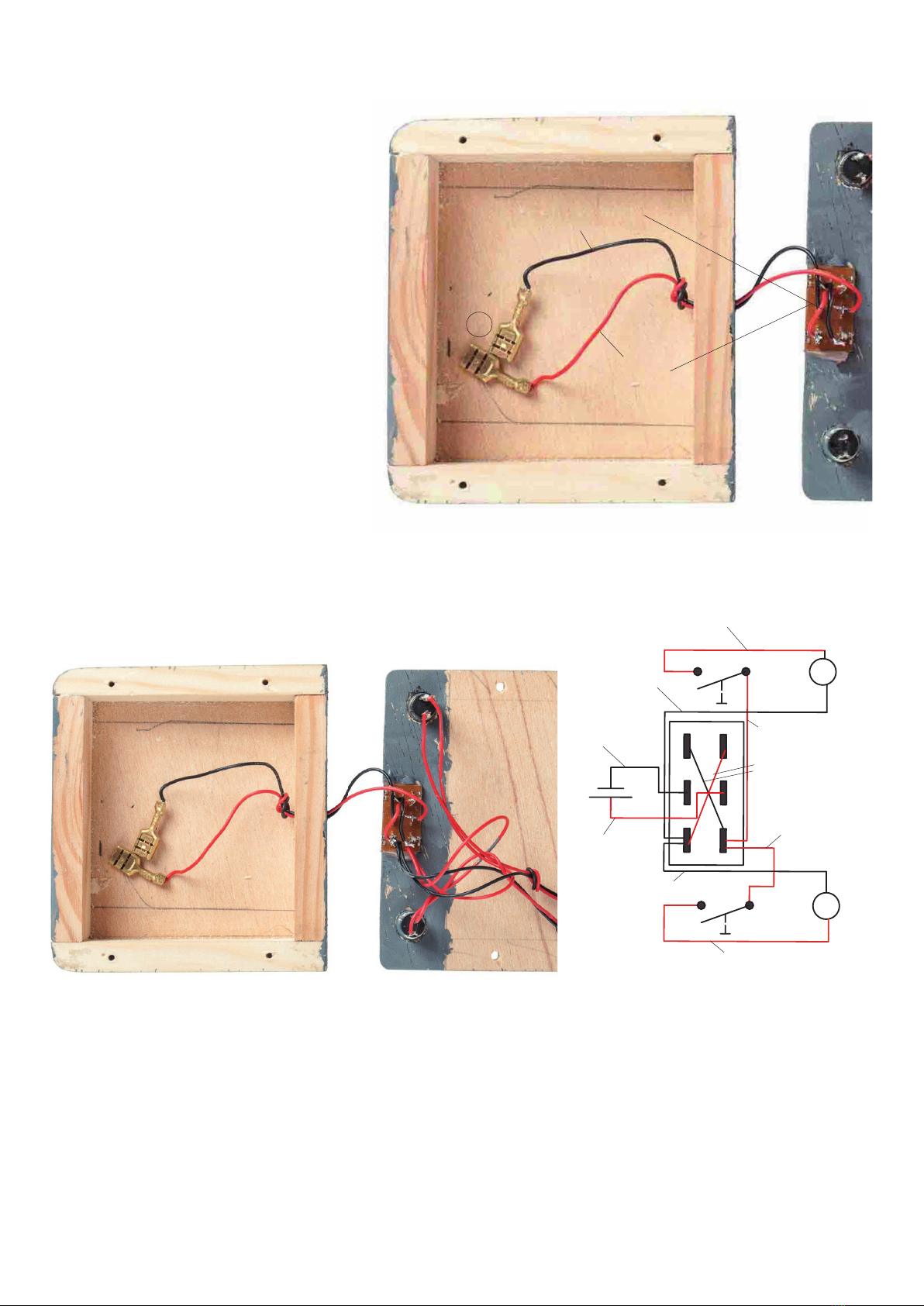
Opitec 115855 User manual

1
E115855#1
115855
Bi-Power-Speedy with Wired
Remote Control
Contents list
Qty Dimensions(mm) Designation Part no.
Plywood 1 200x100x5 Construction control 1
Plywood 1 200x80x8 Construction vehicle 2
Grey Cardboard 1 210x150x1 Construction vehicle 3
Hard Paper Pipe 1 ø 19,5x300 Exhaust 4
Wooden Wheel 1 ø 30 Wheel Rear Axle 5
Impeller 2 ø 45 Wheel Front Axle 6
Wooden Strip 1 350x25x10 Composition Controling 7
Motor 2 Drive 8
Bow 2 21 Attachment Motor 9
Brass Case 1 ø4 x 8 Axle-Box Back Wheel 10
Reducer 2 3/2 Reduction Motor Shaft 11
Push Button 2 Control 12
Slide Switch 1 36x13, 6-polig Switch 13
Tapping Screw 1 2,9x25 Rear Axle 14
Tapping Screw 8 2,9x9,5 Screwing 15
Blade Receptacle 2 Battery Connector 16
Washer 6 7/3,2 Washer 17
Cable red 2 2000 Cabling 18
Cable black 2 2000 Cabling 19
Please Note
The OPITEC range of projects is not intended as play toys for young
children. They are teaching aids for young people learning the skills
of craft, design and technology. These projects should only be un-
dertaken and operated with the guidance of a fully qualified adult.
The finished projects are not suitable to give to children under 3
years old. Some parts can be swallowed. Danger of suffocation!
Required Tools:
sand paper
ne saw or scroll saw
scissor, ruler, pencil
drill ø2.5, ø4, ø 7, ø10mm
wood glue and all purpose adhesive
modeling knife
soldering iron, solder ux

2E115855#2
30
40
80
35
40
90
150
17,5
4
8
150
75
10
Ø 2,5
90°
90°
25
50
300
20
10
10
50
20
10
150
Ø 4
50
300
20
10
10
50
20
10
150
Ø 4
75
50 100
63,3
Instructions to build the vehicle:
1. Transfer the template of the base (page 7) on the
plywood and saw it with the fretsaw. Clean and sand
the sawed edges.
Drill a ø2,5 mm drilling in the side edge. See picture!
2
2
3. Fix each motor with a bow (9) and two screws (15) on the base as shown.
Hint: Direct your attention on the position of the motors. They must be xed right angeled to the base and must be in a
line with each other.
9
9
15
15
15
15
4. Measure and mark 150mm (4a) on the hard paper pipe (4)
from one end and 50mm from the other end (4b). Cut the hard
paper pipe along the marked lines with the jigsaw. Cut the tem-
plate for the pipe (page 7) Lay it round the hard paper piece
and x it with tape.
Cut the 150mm long piece, along the line of the taped templa-
te, into two bevelled parts with the jigsaw.
Take the 50mm piece (4b) and drill a ø4mm hole in one side,
turn the pipe piece and drill a ø4mm hole again. The second
hole is on the other end on the opposite side.
5. Glue the 50 mm hard paper pipe (4b) centered on the
base as shown. Direct your attention on the drilling in
the pipe. It must be straightened to the motor.
4a 4b
4b
4b

3
E115855#1
150
210
6. Fix the bevelled pipe pieces (4a), left and right of the
50mm pipe, on the base as shown.
7. Insert a reducer (11) in the drilling hole of the wheels (6).
In addition put each wheel on a motor axis.
8. Put the brass sleeve (10) into the wooden wheel (5).
Moreover x the wooden wheel with a screw (14) and
3 at washers (17) in the middle of the back axis.
9. Transfer the composition (mouse motive) and the ears on
the grey cardboard and cut it out (template page 9). Cut
the slots (broken line) for the ears with a craft knife. Add
the hole for the cable route with a ticket punch, a knife or a
scissor for example.
Hint: Coloure the composition and the base plate before
assembling.
10. Cut a approx. 200mm long piece of the red and black cable. (18 + 19) Re isolate and tin both sides of all 4 cable parts.
Connect one end of the black long wire with the plus terminal (marked with depression) of the left engine. Take the
second black cable and connect it with the minus terminal of the right engine. Connect the remaining red cables to
the free engine connection (1 each side). Lead all the 4 cables through the under drilling into the 50mm hard paper
pipe and pull them out again through the upper hole.
Moreover thread the cables through the composition, as shown. Push the cardboard under the bow, which xes the
motor. Do not glue the building at the back yet.
6
6
14 5
4a
4b
17
5
10
scratch
score
left
right
driving direction
6
11

4E115855#2
40
80
12,5
Ø 4
90
25
25
40
80
12,5
Ø 4
90
25
25
90 90 8080
12,5
Ø 4
25
40
90 110
200
100
50
12
15
15
12
12
Ø 10
55
20 50
Ø 3
22
Ø 7
A
B
15 15
100
10
7
5
2
A
B
15 15
100
10
7
5
2
11. Cut the wooden strip (7) as shown. Mark the center of a 80mm strip and
drill a hole ø 4mm into it.
Instructions to build the control:
2x
12. Cut the plywood (1) as shown in two parts with 90mm and 110mm. Take the piece which is 110mm long and saw the
opening for the slide switch.
Next drill two drill holes, ø2,5mm, for the push buttons next to the opening. Additionally turn around the plate and
drill a 2mm deep hole with a diameter of 10mm directly over the ø2,5mm drill hole. After that turn around the plate
again and drill one more hole with ø7mm over the existing ø2,5mm drilling hole on each side. For future mounting
drill 4 holes ø 3mm into the base, as shown (1a).
1
1a
1b
7a 7b 7c 7d
13. Glue the pieces 7a-7d on the base (1b), as shown.
7a
7b
7c
7d
1b
14. Glue the slide switch(13) into the opening (Teil 1a) and
put the two push buttons into the drilling holes. Fix them
with the appendant nuts.
1a
Cut

5
E115855#1
MM
MM
Wiring Diagram
15. Take a red and a black cable and cut a
piece of 20 mm of each wire. Now re
isolate the 4 ends and tin them. Connect
the two cables crosswise to the external
connections of the slide switch. (see
diagram; the connections of the slide
switch are the black rectangles; black
cable: from left top to right bottom;
right cable: from left bottom to right
top) Take the red and black 200mm
cable and cut them in half. Re isolate
and tin the wire ends. Furthermore take
one half of the red cable and connect
it with the middle connection of the
slide switch on the right side. After that
take one half of the black cable and
connect it with the middele connection
of the slide switch on the left side. Put
the two cables through the drilling 7d)
and knot them together in the middle.
See picture. Last but not least sold a at
receptacle (16) on each end.
red cable
black cable
16. Take one 100mm long red cable and cut it to 30mm. Re isolate and tin the ends. Now connect one end with the
front left inward facing connection of the slide switch. (In the wiring diagram it is the lowest black rectangle on
the lright side.) Connect the other end to the left push button. (It looks like a seesaw on the diagram) After that
connect one end of the remaining piece of the red cable (70mm) to the same slide switch connection. Connect
the other end with the right push button.
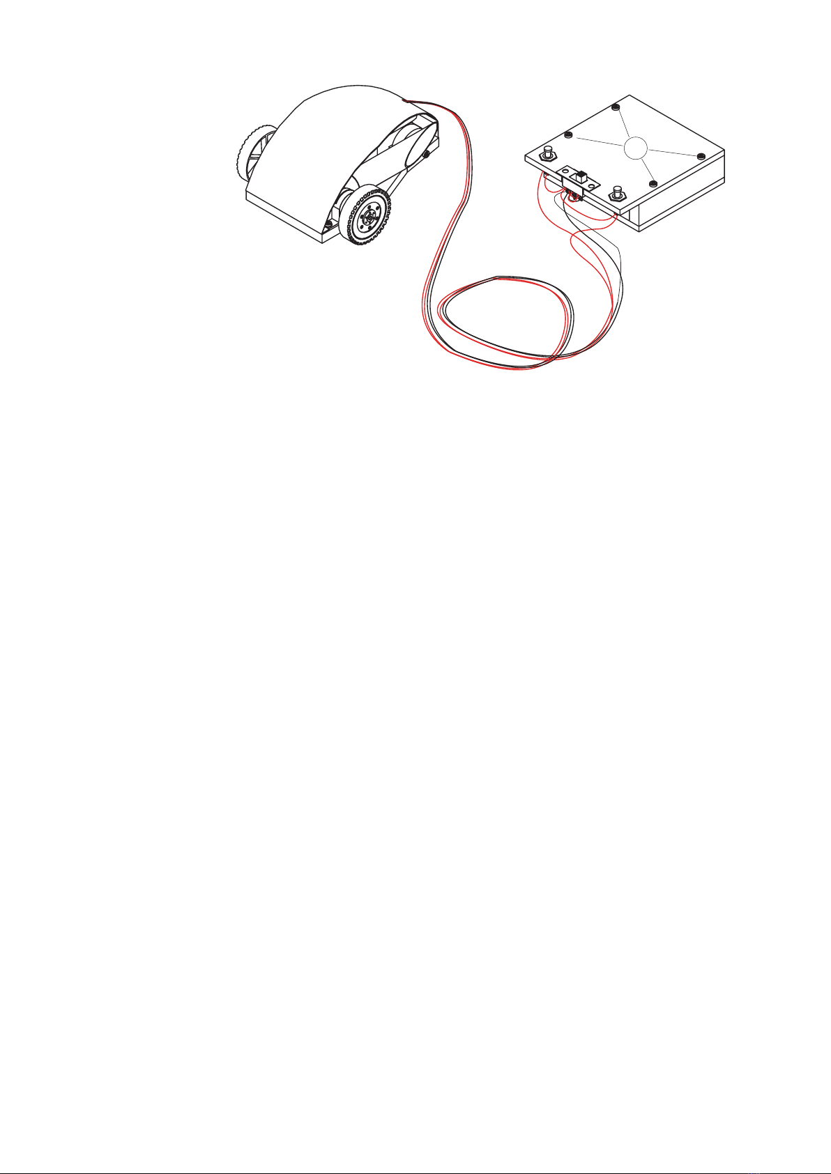
Moreover connect the two long red cables, coming from the engines, to the free connections of the push buttons
and connect the two long black cables, coming from the engines, with the left sided outwards facing slide switch
connection. (It is the lowest black rectangle on the left side) (See wiring diagram) Last put the batteries into the
control box and connect it to the at receptacles, red cable = + and black cable = -.
30mm red cable
70mm red cable
16
100mm
red cable
100mm
black cable
20mm red/black
cable
Cabling of the control:
long red cable left sided motor
long red cable right sided motor
long black cable right
sided motor
long black cable left
sided motor
left
sided
motor
right
sided
motor

6E115855#2
R
L
RV
17. Replace the lid on the control as shown and
x it with 4 screws (15).
Hint:
After function control glue the construction on the base with wood
glue.
15
Funktionsbeschreibung:
Taster steuern die Motore einzeln links und rechts. Der Schiebeschalter ist ein Umpolschalter, d.h. Stellung V, Spee-
dy fährt vorwärts, Stellung R, Speedy fährt rückwärts.

7
E115855#1
30
40
80
35
40
90
150
17,5
4
8
150
75
10
Ø 2,5
50 100
63,3
Template base
Scale 1:1
Template hard paper pipe
Scale 1:1

8E115855#2

9
E115855#1
150
210
Template grey cardboard mouse
Scale 1:1
Popular Remote Control manuals by other brands

LightwaveRF
LightwaveRF LW825 Operation manual

Mercury
Mercury 4000 MPC GEN II installation instructions

Brilliant Wonders
Brilliant Wonders 25650-100 Series Operation & Installation Quick Reference

Tyco
Tyco PG9929 installation guide

Bose
Bose Acoustic Wave music system II. owner's guide

Fanotec
Fanotec MECHA C2 user guide