Elsner Remo 8 User manual

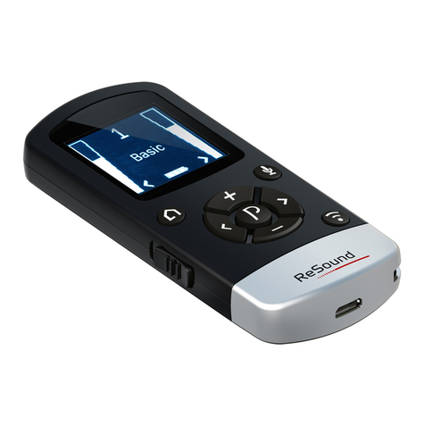
Remo 8 wireless remote control 1
Remo 8 hand-held transmitter software version 1.1 and up • Issued 28/07/2011 • The right to make technical changes is reserved. Errors excepted.
Elsner Elektronik GmbH • Herdweg 7 • D-75391 Gechingen • Germany • Phone: +49 (0) 70 56/93 97-0 • Fax: -20 • info@elsner-elektronik.de • www.elsner-elektronik.de
1. Description
The Remo 8 wireless remote control offers an Up/Down/Stop or On/
Off control for eight channels and can be set up with vari-
ous devices. If the remote control is not being used, it is sa-
fely placed in the included magnetic wall-holder.
Remo 8 is suitable for the following devices:
• WS1000 Color control (version 1.1 and up), WS1 Color
• Solexa control (v. 3.6 and up), Arexa (v. 3.7 and up)
• WL305, WL610 ventilators (version 4.0 and up), WFL
air supply (version 2.0 and up)
• RF-Relay (version 2.0 and up), RF-MSG motor control
unit, RF-VM ventilation module
• XS MSG2-AP wireless motor control unit (v.2.0 and up)
• Lixa control unit
The software version of the device must be appropriate for interaction
with the remote control!
Moisture is harmful to the electronic components of
the hand-held transmitter. You must therefore:
• Not leave it in the rain
• Not leave it outside overnight
• Protect it from frost
1.1. Scope of delivery
• Hand-held transmitter with battery
• Wall-mounted holder with screw covers
1.2. Technical data
The following standards were consulted during the evaluation of this
product with respect to electromagnetic compatibility:
• EN 301 489-1 V1.8.1:2008-04
• EN 300 220-2 V2.1.2:2007-06
The product was tested by an accredited EMC-lab in compliance with
the above-named standards.
2. Installation and commissioning
2.1. Installing the wall-mounted holder
2.2. Notes on radio devices
The design of radio communication devices must pay attention to suf-
ficient radio signal reception. The range of radio controls is limited by
legal regulations applicable to radio devices and by local structural con-
ditions. Avoid source of disturbance and obstacles between transmitter
and receiver that could disrupt radio communication. These include for
example:
• Walls and ceilings (especially concrete).
• Metallic surfaces close to the radio network participant (e.g.
aluminum frame of a winter garden).
• Other network participants and strong local transmitting devices
(e.g. radio headphones) transmitting on the same frequency (868.2
MHz). Therefore, keep a minimum distance of 30 cm between
radio transmitters.
2.3. Configuring and deleting a connection
Each of the hand-held transmitter's eight channels can control one or
more radio channels (units).
2.3.1. WS1000 Color / WS1 Color control systems
Configuration:
Deletion:
2.3.2. XS MSG2-AP motor control unit
Configuring and deleting should only be performed
by a trained electrician!
Configuration:
Deletion:
Housing Plastic
Colours • white/light grey
• aluminium/graphite (partially painted)
Installation with magnetic wall-holder
Protection category IP 40
Dimensions Transmitter approx. 41 x 140 x 21 (WxHxD,
mm), Holder approx. 54 x 150 x 11 (WxHxD,
mm)
Total weight approx. 95 g
Ambient temperature Operating 0…50 °C, storage -10…+60 °C
Ambient humidity max. 95% rH, avoid condensation
Operating voltage 3 V CR2032 type battery
Radio frequency 868.2 MHz
Channels 8
The holder must be firmly screwed to the wall.
Please use suitable dowels and screws as
supports. The screws should then be covered
with the provided screw covers.
The hand-held transmitter is held in position in
its tray with magnets.
1. Bring the control unit into the set-up readiness state: Menu
System > Installation > Wireless connection > Setup.
Please also follow the instructions in the manual.
2. Press the centre of the +/- button on the hand-held
transmitter until an "S" for Setup and a number
(channel) are displayed.
The channel selected will not affect the configuration of
the WS1000 Color/WS1 Color.
3. Press the Up arrow button to establish the wireless
connection with the control system.
4. The remote control is now configured for the control system.
The System > Installation > Wireless connection > Status menu
item allows you to give the hand-held transmitter a separate
name and assign individual drives and devices to the hand-held
transmitter channels.
1. Delete the hand-held transmitter on the control system menu:
Menu System > Installation > Wireless connection > Delete.
Please also follow the instructions in the manual.
1. Bring the desired channel of the motor control unit into the set-
up readiness state (see manual chapter "Motor control unit
wireless connection
- Remo 8").
2. Bring the hand-held transmitter into the set-up
readiness state by pressing the centre of the +/- button
on the hand-held transmitter until an "S" for Setup and
a number (channel) are displayed.
3. Using + or - change the hand-held transmitter channel
that you would like to connect to the motor control unit
channel (L 1 to L8).
4. Press the Up arrow button to establish the wireless
connection with the motor control unit.
The hand-held transmitter channel is now configured
to the channel of the motor control unit.
1. Bring the desired channel of the motor control unit into the set-
up readiness state (see manual chapter "Motor control unit
wireless connection - Remo 8").
2. Bring the held-held transmitter into the deletion
readiness state. For this purpose press the +/- button in
the centre till "S" appears in the display. Then press
again till a "C" for Clear appears in the display.
3. Using + or - change to the hand-held transmitter that
you want to delete (C 1 to C 8).
4. Press the Up arrow button to delete the wireless
connection to the motor control unit channel.

Remo 8 wireless remote control 2
Remo 8 hand-held transmitter software version 1.1 and up • Issued 28/07/2011 • The right to make technical changes is reserved. Errors excepted.
Elsner Elektronik GmbH • Herdweg 7 • D-75391 Gechingen • Germany • Phone: +49 (0) 70 56/93 97-0 • Fax: -20 • info@elsner-elektronik.de • www.elsner-elektronik.de
2.3.3. Solexa / Arexa control units, WL305 / WL610
/ WFL ventilators, RF relays, RF-VM
The configuration and deletion should only be perfor-
med by a trained electrician!
Configuration:
Deletion:
2.3.4. RF-MSG motor control units, RF relays-UP
The configuration and deletion should only be perfor-
med by a trained electrician!
Configuration:
Deletion:
2.4. Operating devices/motors using the
transmitter
Sequence of ventilation steps for roof-top fan WL305/610:
Exhaust air8 - 7 - 6 - 5 - 4 - 3 - 1 - Off - Recirculation air 1 - 2 - 3 - 4 -
5 - 6 - 7 - 8
3. Care and maintenance
Clean the hand-held transmitter with a damp cloth. Do not use deter-
gent.
3.1. Troubleshooting
Device/drive does not react to button press:
3.2. Replace the battery
Dispose of the used battery properly - empty batteries should not be th-
rown away in household refuse.
1. Bring the hand-held transmitter into the set-up
readiness state by pressing the centre of the +/- button
on the hand-held transmitter until an "S" for Setup and
a number (channel) are displayed.
2. Using + or - change to the hand-held transmitter that
you want to program (L 1 to L 8).
3. Press the programmer button inside the device using an
insulated screwdriver.
Now you can control the device with this hand-held transmitter
channel.
1. Bring the held-held transmitter into the deletion
readiness state. For this purpose press the +/- button in
the centre till "S" appears in the display. Then press
again till a "C" for Clear appears in the display
2. Using + or - change to the hand-held transmitter
channel that you want to delete (C 1 to C 8).
3. Now press the programmer button inside the device using an
insulated screwdriver. The wireless connection is deleted.
1. Bring the hand-held transmitter into the set-up
readiness state by pressing the centre of the +/- button
on the hand-held transmitter until an "S" for Setup and
a number (channel) are displayed.
2. Using + or - change to the hand-held transmitter
channel that you want to program (L 1 to L 8).
3. Now activate the RF-MSG voltage supply. The motor control unit
automatically configures a connection to the control unit/remote
control 3 seconds after the mains voltage is applied.
Now you can control the RF-MSG-connected drive with this
hand-held transmitter channel.
1. Bring the held-held transmitter into the deletion
readiness state. For this purpose press the +/- button in
the centre till "S" appears in the display. Then press
again till a "C" for Clear appears in the display.
2. Using + or - change to the hand-held transmitter
channel that you want to delete (C 1 to C 8).
3. Now activate the RF-MSG voltage supply. The motor control unit
will be cleared automatically 3 seconds after the mains voltage
is applied.
1. Select the hand-held transmitter channel that you want
using the + and - buttons.
2. You can now operate the assigned device and/or drive
using the Up, Down and Stop buttons.
Switching
devices
Dimming
light
Elsner
roof-top
fans
Moving
drives
1
.On/Off Short:
Off/On (last
dim value)
Long:
Brighter
1 step up Up
Short:
Incremental
operation
Long:
Normal drive
(up to end
position)
2
.Off On/Off Off/closed Stop
On/Off Short:
Off/On (last
dim value)
Long:
darker
1 step down Down
Short:
Incremental
operation
Long:
Normal drive
(up to end
position)
Cause Procedure
Wireless contact interrupted,
transmitter too far from receiver
Choose another location
Battery drained Replace the battery
No voltage to or faulty receiver
unit
Switch on receiver unit (e.g.
control unit). Should wireless
contact still not be established,
please contact Customer Service
1. Open the housing panel on the rear of the hand-held transmitter
(using a Phillips screwdriver).
2. Lift the used battery carefully out
of the holder. Be careful of the
clips when inserting the new
battery.
CR2032 type battery, 3 V.
3. Screw the rear housing panel closed again.
Table of contents
Other Elsner Remote Control manuals

