Oppermann Regelgeräte STG 1.2 User manual

Fire Protection | Data sheet No. 43104 | Version 02-2016 | 1| 8
Control unit STG 1.2
for DRM ceiling smoke detector/DKM manual call point – bus compatible
Technical data
Supply voltage: 24 V AC +/-10%
24 V DC +15%/ -10%
Power consumption: 250 mA (normal operation)
Imax 2.5 A (alarm – 20 detectors)
Imax 6.2 A (0.02 s short circuit)
Relay outputs:
Alarm: 1 changeover contact
240 V AC/30 V DC, 8 A
1 NC
240 V AC/30 V DC, 8 A
Contamination: 1 changeover contact
400 V AC/300 V DC, 6 A
Failure: 1 changeover contact
400 V AC/300 V DC, 6 A
Service: 1 changeover contact
(service mode) 400 V AC/300 V DC, 6 A
Notications:
Display: Plain text display status
DRM/ DKM, conguration
Alarm: red LED
Contamination: yellow LED
Failure: yellow LED
Operation: green LED
Housing: plastic ABS
Dimensions (W x H x D): 160 x 85 x 50 mm
Installation: DIN-rail, panel
Protection class: IP20
Ambient temperature: 0 °C to 50 °C
Connection: spring terminals 0.5 – 2.5 mm²
• Can connect up to 99 DRM 3.3 or DRM 3.3-N
ceiling smoke detectors/ DKM 3.3 manual call
points
• Possible to query each detector as to status
and contamination
• Large LCD display and 4 additional LEDs
• RS485 Mod-Bus interface for informal
transmissions to the building management
system (BMS)
• 4 changeover contacts for alarm, failure,
service and contamination
• 1 NC for alarm
• Monitoring for short circuits and cable breaks
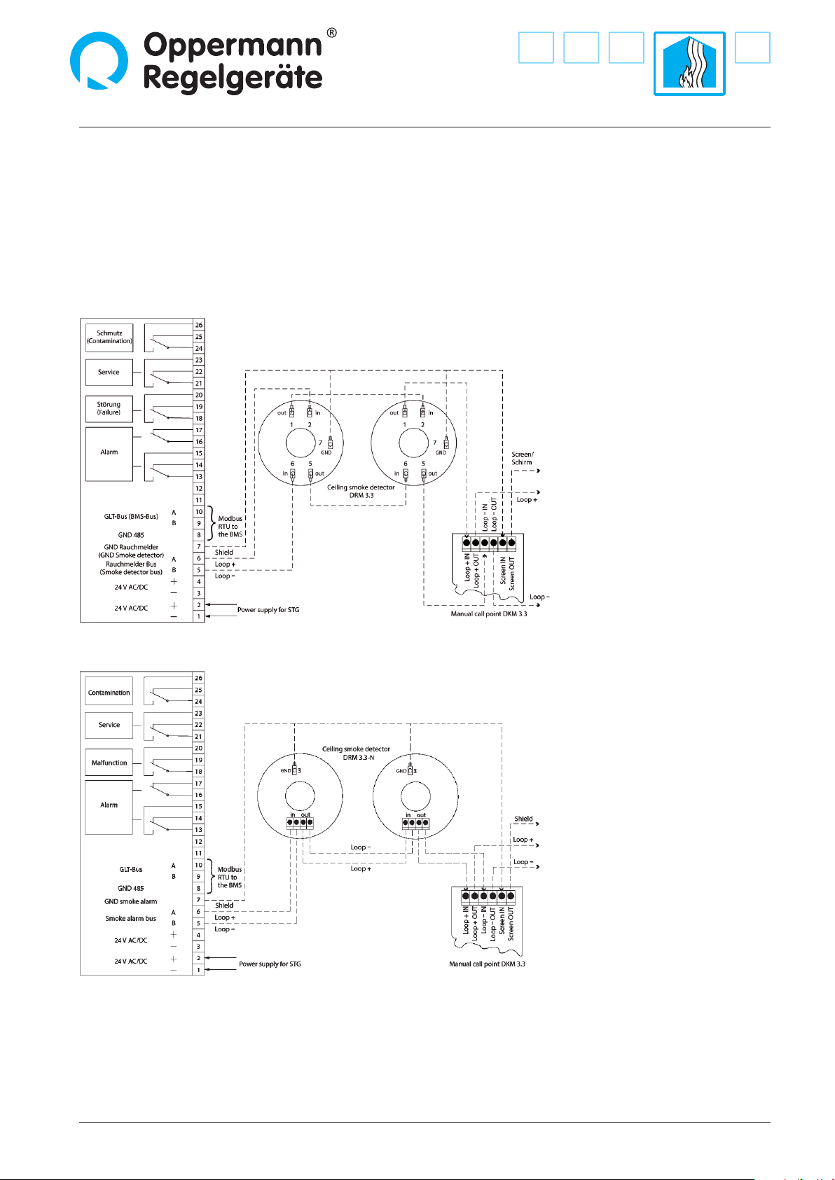
Function
Up to 99 type DRM 3.3 or DRM 3.3-N/DKM 3.3 ceiling smoke
detector or manual call points can be monitored by the STG con-
trol unit. The STG communicates with its connected detectors
by way of their security monitored system ring buses. Smoke
alarms, failure and contamination messages are all forwarded
from the detectors to the STG and shown on a display. This
makes it possible for a technician or custodian to supervise all
the connected detectors at a glance. The STG has one changeo-
ver relay each for alarm, contamination, failure and service mode
signalling. With the alarm message there is a relay available
which serves as an NC contact. With this relay the messages can
be reported to a central building management system (BMS).
The STG 1.2 additionally has an RS-485 interface to the BMS,
which also exports all of this data including the status of indivi-
dual detectors via a Modbus RTU protocol. With this interface it
is also possible to evaluate the STG via PLC control or a PC.
Important note: In addition, please note the separate
DRM/ DKM data sheets.
If an alarm occurs at one or more connected detectors, the red
LED lights up on the STG, a message is issued to the STG display,
and the corresponding NC contact and changeover contact at
the STG drop out. By pressing the reset button the relay contact
can be restored, but the corresponding alarm must be termina-
ted/disabled rst. In case of failure, connection problems as well
as contamination of one or more of the detectors, the yellow
contamination LED on the STG lights up and the corresponding
changeover relay of the STG drops out. If no connection to a
duct smoke detector can be made, a failure message appears
on the STG. If a new detector is connected in the service mode,
a corresponding message appears on the display. If the STG is
in service mode the service relay drops out. Failure and alarm
messages of the connected detectors must be acknowledged
once more through the STG“alarm /reset” button.

Control unit STG 1.2
2| 8| Fire Protection | Data sheet No. 43104 | Version 02-2016
Operation
The STG is intuitively operated by means of 4 keys:
The STG 1.2 has two menu levels available:
• Home menu:
• Display overall status/ overview
• Submenus:
• Save and delete the conguration
(switch to operating mode or service mode)
• Address assignment for the STG
(if multiple STGs are to be integrated in one bus)
• Bus scan of the connected detectors
• Detailed view of the connected duct smoke detectors
(detector status, detector contamination level)
• Display of the STG rmware
By pressing the Home button the Home menu is always called
up. The Home menu is reached by pressing the up or down
button in the various sub-menus. The exact functionality is
described in plain text in the relevant sub-menu on the display.
2 operating states for the STG must be dierentiated:
• Service mode:
In service mode, the failure LED ashes and the text “Service
Modus”blinks in the display. The “Service”relay drops out
(terminal 21 + 23 open, terminal 21 + 22 closed).
As long as no conguration is saved, the STG is always in ser-
vice mode and it will continuously carry out a bus scan.
By simultaneously pressing the up and down keys an existing
conguration will be stored in the submenu. When the cong-
uration is stored it will automatically leave the service mode.
Note: The service mode is used to integrate a new detector or
for system maintenance.
• Operating mode:
The operating mode is accessed by storing the selected
conguration. All connected detectors will be monitored and
failures/alarms will be evaluated. The operating mode can be
left by deleting the stored conguration.
All connected smoke alarms can be displayed in the sub-
menu with the up and down keys. This is where the detector‘s
bus address, status, and contamination (only with ceiling
smoke detectors) are displayed.
Alarms and error messages are self-sustaining and must be
acknowledged once more on the STG (with the alarm/ reset
button) after correction.
Functionality test
By pressing the reset button for a few seconds all the LEDs light
up and all the relay inputs are connected.
Installation instructions
All work must be carried out by a suciently qualied crafts-
man. Current local rules and regulations (e.g. building regula-
tions, electrical/VDE guidelines, etc.) are to be observed.
Installers and operators are required to be adequately infor-
med before operation. We assume no liability for misprints
and changes after printing. Compliance with operating and
installation instructions is also included within the regulations
of intended use. We assume no liability for damages caused
by improper use. Operating licenses and guarantees and all
warranty claims will be voided in the event of unauthorized
modications or any tampering with the device.
Alarm
Contamination
Operation
Failure

Fire Protection | Data sheet No. 43104 | Version 02-2016 | 3| 8
Control unit STG 1.2
Electrical connection
Work on electrical systems or equipment must be carried out only by a qualied electrician or by instructed personnel under the
direction and supervision of a qualied electrician according to electrotechnical regulations.
Please ensure to connect the current ceiling smoke detector model. The older version, type DRM 3.3, has been replaced by version
DRM 3.3-N.
Contact depictions are with the
power o (alarm)
Contact depictions are with the
power o (alarm)
Connection of type DRM 3.3
Connection of type DRM 3.3-N
The power supply to the detector takes place via the system ring bus. The current in the ring bus is limited to 1 A.
The bus line is to be shielded on both sides.

Control unit STG 1.2
4| 8| Fire Protection | Data sheet No. 43104 | Version 02-2016
The maximum wire length for the bus is 250 m (loop length
500 m).
A separate, individualized bus address between 1 and 99 is set for
each connected detector. This is done by the PG 3.3 programming
device (accessory). The standard bus address 127 is always set for
DRM ceiling smoke detectors. For manual call points the standard
address is 1. If desired, Oppermann detectors will be delivered
with individual bus addresses congured (specify when ordering).
The positioning of the addressed DRM/DKM in the ring bus is
arbitrary. A fault signal occurs with doubled assignments/connec-
tions at the same detector address in the ring bus. If the detector
address is changed, the detector needs to be re-linked in the STG‘s
service mode.
Note: Due to the increased power consumption in cases of alarm,
an additional failure message may occur during simultaneous
triggering of more than 20 detectors. Therefore not more than 20
re alarms should be installed in the same re area.
In order to limit the maximum current during simultaneous
alarms from many detectors, the STG must be secured on site
with a 2.5 A delay fuse. The external power supply for the STG
must be designed so that during a short-circuit at the system ring
bus a maximum current of 6.2 A can be delivered for a duration of
0.02 seconds.
When wiring the Modbus the technical guidelines must be
considered.
Only wiring cables which comply with the recommendations of
the EIA 485 guidelines may be used for the Modbus.The bus cable
must be laid at a distance of at least 20 cm from other lines. It
should be installed in a separate, conductive and grounded cable
trunking. It is important to ensure that no potential dierences
between devices can occur on the Modbus (perform equipoten-
tial bonding). The cable shield must be connected to GND on both
sides.
Ensure EMC-compliant wiring:
Signal and bus lines are susceptible to interference. Motor cables
tend to be prone to disruptions. Lines that are susceptible to inter-
ference and prone to disruption should be placed at the greatest
possible distance from one another. The interference immunity
of signal and bus cables increases when the cables are laid close
to the ground potential. If possible, avoid long wires and make
sure that they are installed in areas of less interference. Avoid long
parallel segments of cable that are either susceptible or prone to
interference.
Protocol RS485 BMS bus interface
Type: Modbus RTU
Baud rate: 9600
Data bits: 8
Start bits: 1
Stop bits: 1
Parity: even
Polling: > 100 ms (important)
Development status: Firmware version 1.0 or later (STG_X0907aa100.hex)
Query to the STG 1.2
Byte0 Byte1 Byte2 Byte3 Byte4 Byte5 Byte6 Byte7
MSB LSB MSB LSB LSB MSB
Address Function Start address Number of registers (1-126) CRC
To receive a message from the STG 1.2, 8 bytes must be sent: the STG’s address, function, start address, number of registers and
nally the redundancy check.
Byte 0:
STG’s address
Byte 1:
Function byte. With function byte = 3
(Read Holding Register), the STG returns an answer.
Byte 2 and Byte 3:
Start address for the data to be read out in the register
Byte 4 and Byte 5:
Number of registers (1 register = 2 bytes), which are read out.
Values between 1 and 125 are permitted.
Byte 6 and Byte 7:
Check sum (CRC).
This interface is for information only for the building management system (BMS) and should not be used for the active connection
of smoke extraction systems.

Fire Protection | Data sheet No. 43104 | Version 02-2016 | 5| 8
Control unit STG 1.2
Response from the STG 1.2
The response from the STG 1.2 appears as follows:
Byte 0 Byte 1 Byte 2 Byte 3 Byte 4 Byte 5 Byte 6 Byte 7 Byte 8 Byte Byte Byte n Byte
n + 1
Byte
n + 2
Byte
n + 3
MSB LSB MSB LSB MSB LSB MSB LSB MSB LSB LSB MSB
STG
address
Func-
tion
Number
of
databytes
Register x Register x+1 Registerx+2 …….. Register y CRC
At the outset the address of the STG 1.2 and the query function are always returned. Then the designation follows regarding the
number of databytes (2 bytes of data are incurred per register). Thereafter the data (register) follows. The register set is dependent
on the query, and can vary between 1 and 125.
Register description:
Each register consists of 2 bytes. With Modbus RTU, it is possible to send 250 bytes of data (MSB is sent rst). In this way a total of 125
registers can be read at once with one query.
Register address Description
0 STG general status
1 Number of connected detectors
2 Status of the detector at Address 1
3 Measured value of the detector at Address 1
4 Contamination in the detector at Address 1
5 Status of the detector at Address 2
6 Measured value of the detector at Address 2
7 Contamination in the detector at Address 2
8 …
9 ...
296 Status of the detector at Address 99
297 Measured value of the detector at Address 99
298 Contamination in the detector at Address 99

Control unit STG 1.2
6| 8| Fire Protection | Data sheet No. 43104 | Version 02-2016
General status of the STG (Register address 0):
Bit 15 - 8:
Bit 15 Bit 14 Bit 13 Bit 12 Bit 11 Bit 10 Bit 9 Bit 8
Alarm LED Contamination
LED Failure LED Operation
LED Alarm relay Failure relay Service relay Contamination
relay
Bit 7 - 0:
Bit 7 Bit 6 Bit 5 Bit 4 Bit 3 Bit 2 Bit 1 Bit 0
Address error Contamination
99 %
Contamination
70 - 98 % Alarm Detector
error
Detector
failure Start Service mode
Number of connected detectors (Register address 1)
This register indicates how many detectors are connected to the STG.
Bit 15: 1: Alarm LED lights up
0: Alarm LED does not light up
Bit 14: 1: Contamination LED lights up
0: Contamination LED does not light up
Bit 13: 1: Failure LED lights up
0: Failure LED does not light up
Bit 12: 1: Operation LED lights up
0: Operation LED does not light up
Bit 11: 1: Alarm relay energized
0: Alarm relay de-energized
Bit 10: 1: Failure relay energized
0: Failure relay de-energized
Bit 9: 1: Service relay energized
0: Service relay de-energized
Bit 8: 1: Contamination relay energized
0: Contamination relay de-energized
Bit 7: 1: Multiple detectors at one address
0: No address error
Bit 6: 1: A connected KRM is contaminated at 99%
0: No connected KRMs are contaminated at 99%
Bit 5: 1: Contamination alert exists
0: No contamination alert exists
Bit 4: 1: Alarm
0: No alarm
Bit 3: 1: Detector error. A detector has reported
an error to the STG.
0: No detector error
Bit 2: 1: Smoke detector failure. Detector no longer
recognized in the bus
0: No smoke detector failure
Bit 1: 1: A detector is in activation
0: No detector is in activation
Bit 0: 1: STG is in service mode
0: STG is in operating mode

Fire Protection | Data sheet No. 43104 | Version 02-2016 | 7| 8
Control unit STG 1.2
Status for the detector:
The status for each detector can be found at the following address:
Address: 3 x n- 1 n: Address of the detector = (1 -99)
Bit 15- 8 are always 0 and have no eect.
Bit 7 -0:
Bit 7 Bit 6 Bit 5 Bit 4 Bit 3 Bit 2 Bit 1 Bit 0
Service
mode Start 99 %
Contamination Address error Failure Alarm Status Status
Bit 7: 1: STG is in service mode
0: STG is in stored mode (operation)
Bit 6: 1: Detector is in start mode
0: Detector is not in start mode
Bit 5: 1: Contamination alarm
(detector is 99 % contaminated).
0: No contamination alarm
Bit 4: 1: Detector has an internal error
0: No internal error
Bit 3: 1: Malfunction
Detector no longer recognized in the bus
0: No malfunction
Bit 2: 1: Alarm
0: No alarm
Bit 1 - 0:
0: No detector connected at this address
1: DRM connected
2: DKM connected
3: Address error: multiple detectors are
connected at this address
Measured value for the DRM:
255 = Alarm; < 255 = the chamber of the DRM is no longer in alarm state and the alarm can be deleted.
With one DKM, this register has no eect
The measured value for each DRM can be found at the following address:
Address: 3 x n n: Address of the detector = (1 -99)
Contamination of the DRM:
The degree of contamination in % for each DRM is located in this registry.
With one DKM, this register has no eect
Contamination for each DRM can be found at the following address:
Address: 3x n+ 1 n: Address of the DRM = (1-99)

8| 8| Fire Protection | Data sheet No. 43104 | Version 02-2016 Specications subject to change.
Control unit STG 1.2
Oppermann Regelgeräte GmbH | Im Spitzhau 1 | 70771 Leinfelden-Echterdingen, Germany
Error code
If there is an incorrect function code, an invalid register address, or if too many registers are requested, an error code will be sent.
(With an incorrect CRC no error code is sent!)
Byte 1 Byte 2 Byte 3 Byte 4 Byte 5
STG address Function Error code CRC (LSB) CRC (MSB)
Byte 0
Address of the STG 1.2
Byte 1
Function byte. Here the function byte for the query is sent back. However, the MSB is set by the function code.
For example: Function byte received = 3 (bin: 00000011)
Reply with function byte = 131 (bin: 10000011)
Byte 2
Error code. The type of error it concerns is communicated here.
The following error messages are generated by the STG 1.2:
Error code = 1: Invalid function code.
With the STG 1.2 only function code = 3 is valid.
For all other functions, an error code is returned.
Error code = 3: Data error.
Requested register address does not exist or the desired register set is not allowed.
Byte 3 and Byte 4
CRC
Table of contents
Popular Control Unit manuals by other brands

saia-burgess
saia-burgess PCD2.W525 Hardware manual

WEG
WEG DeviceNet CFW500 Installation, configuration and operations guide

Kobelt
Kobelt 2544 Owner's Operation, Installation & Maintenance Manual

Honeywell
Honeywell REDLINK ERM5220R Product data

Evco
Evco C-PRO 3 CLIMA sistema+ Installer manual

Duali
Duali DE-ABCM6 user manual

Emerson
Emerson CASH VALVE FRM Installation, Maintenance, and Parts Manual

Singer Valve
Singer Valve 106-RPS-D Installation, operating and maintenance instructions

DVC
DVC 3500 Installation, operation and maintenance

Armstrong
Armstrong OB-2000PT Integral Assembly instructions

Honeywell
Honeywell Resideo ADEMCO 4101SN V-Plex Installation and setup guide

ZIEHL-ABEGG
ZIEHL-ABEGG Unicon CXE/AVC 3 manual