manuals.online logo
Brands
  1. Home
  2. •
  3. Brands
  4. •
  5. Toa
  6. •
  7. Control Unit
  8. •
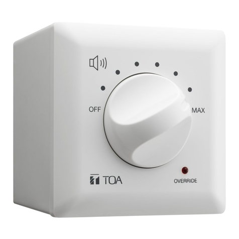
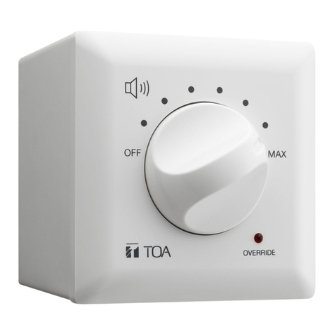
  9. Toa AT-063Ap User manual

Toa AT-063Ap User manual

INSTRUCTION MANUAL
ATTEnuators AT-063Ap, at-303Ap, at-603ap
Thank you for purchasing TOA’s Attenuator.
Please carefully follow the instructions in this manual to ensure long, trouble-free use of your equipment.
1. SAFETY PRECAUTIONS
•Before installation or use, be sure to carefully read all the instructions in this section for correct
and safe operation.
•Be sure to follow all the precautionary instructions in this section, which contain important
warnings and/or cautions regarding safety.
•After reading, keep this manual handy for future reference.
WARNING
CAUTION
Indicates a potentially hazardous situation which, if mishandled, could
result in death or serious personal injury.
Indicates a potentially hazardous situation which, if mishandled, could
result in moderate or minor personal injury, and/or property damage.
WARNING
When Installing the Unit
•Do not expose the unit to rain or an
environment where it may be splashed by
water or other liquids, as doing so may result
in fire or electric shock.
•Refer all installation work to the dealer from
whom the unit was purchased. Installation for
requires extensive technical knowledge and
experience. The unit may fall off if incorrectly
installed, resulting in possible personal injury.
•Install the unit only in a location that can
structurally support the weight of the unit and
the mounting bracket. Doing otherwise may
result in the unit falling down and causing
personal injury and/or property damage.
•Since the unit is designed for indoor use, do
not install it outdoors. If installed outdoors, the
aging of parts causes the unit to fall off,
resulting in personal injury. Also, when it gets
wet with rain, there is a danger of electric
shock.
•Do not use other methods than specified to
mount the unit. Extreme force is applied to
the unit and the unit could fall off, possibly
resulting in personal injuries.
•Do not mount the unit in locations exposed to
constant vibration. The unit can be damaged
by excessive vibration, potentially causing the
unit to fall, which could result in personal
injury.
•Use screws that are appropriate for the
ceiling's or wall's structure and composition.
Failure to do so may cause the speaker to
fall, resulting in material damage and possible
personal injury.
•Tighten each screw securely. Ensure that the
bracket has no loose joints after installation to
prevent accidents that could result in personal
injury.
•Take care not to pinch the cables when
wiring, making cable wiring by force may
result in fire or electric shock.
•Use the specified plate in combination. Doing
otherwise may cause the unit or component
to fall off, resulting in personal injury.
CAUTION
When Installing the Unit
•Avoid installing the unit in humid or dusty
locations, in locations exposed to the direct
sunlight, near the heaters, or in locations
generating sooty smoke or steam as doing
otherwise may result in fire or electric shock.
•Avoid touching the unit's sharp metal edge to
prevent injury.
•To avoid electric shocks, be sure to switch off
the amplifier’s power when connecting the
unit.
When the Unit is in Use
•Do not operate the unit for an extended
period of time with the sound distorting. Doing
so may cause the connected speakers to
heat, resulting in a fire.
•Have the unit checked periodically by the shop
from where it was purchased. Failure to do so
may result in corrosion or damage to the unit or
its mounting bracket that could cause the unit to
fall, possibly causing personal injury.
2. GENERAL DESCRIPTION
The AT-063AP, AT-303AP, and AT-603AP are the wall -mount transformer type attenuators
capable of handling a wide range of input power. They feature 5-level fine volume adjustment and a
push-in terminal block for easy cable connection.
3. FEATURES
•Volume adjustable to 5 levels (0 dB, −6 dB, −12 dB, −18 dB and OFF)
•A push- in colored terminal block provides an easy cable connection.
4. SPECIFICATIONS
Model
AT-063AP
AT-303AP
AT-603AP
Input volume
0.5–6W
0.5–30W
0.5–60W
Input Impedance
20 kΩ – 1.7 kΩ
20 kΩ – 330 Ω
20 kΩ – 170 Ω
Attenuation
5 steps (0 dB, –6 dB, –12 dB, –18 dB,OFF)
Applicable Cable
600 V vinyl-insulated cable (Indoor Vinyl or Heat-resistant Indoor Vinyl cable)
Solid cable: ø0.8 (0.03") –ø1.6 (0.06") mm
Finish
Knob, panel, plate: ABS resin, white (RAL 1013 or equivalent color)
Case:
ABS resin, black
Terminal
Push-in connector
Dimensions
70 (w) x 120 (h) x 52.4 (d) mm (2.76” x 4.72” x 2.06”) (with plate)
41 (w) x 108 (h) x 52.4 (d) mm (1.61” x 4.25” x 2.06”) (attenuator only)
Weight
170 g (0.37 lb)(unit only)
210 g (0.46 lb)(unit only)
Note: The design and specifications are subject to change without notice for improvement.
• Accessories
Plate....................................................................1
Machine screw M3.5 x 5 (mounted to the plate) .....2
Machine screw M4 x 35 ........................................2
•Optional products
Plate: YP-1AF
Wall mounting box: YS-11A
Flush-mount box: YC-801
Wall-mount box: YC-802
5. INSTALLATION
Step 1. Install the electrical box into the wall.
Step 2. Make a hole in the wall to mount the unit, then pull out the cables from the wall.
Step 3. Connect the cables to the unit’s terminal block.
Note: For details, see “Connection” on the next page.
Step 4. Mount the unit in the electrical box using the 2 supplied screws.
Step 5. Attach the plate (supplied) to the Attenuator.
51 − 59 mm
(2.01" − 2.32")
Wall
2Cable
4
1
Machine screw M4 x 35
5
8
3
.
m
m
2
9
"
)
(
3
.
3
(Accessory)
(3.74" − 4.06")
95 − 103 mm
Attenuator
5
Plate (Accessory)
Machine screw M3.5 x 5
(Accessory)
Note: When using the supplied screws to install the unit
to the electrical box, the distance between the wall
surface and the electrical box’s surface should be
less than 27 mm (1.06") as shown below.
Wall
A recessed
electrical box
Max. 27 mm (1.06")
Take care not to pinch the lead-in cables when mounting the unit WARNING particularly in a shallow
wall-mount box (37 mm or 1.46" deep ). Do not press the cables into the shallow box by force, as doing so
may
damage the unit, resulting in fire or electric shock.
6. CONNECTION
Step 1. Strip the cable sheath 9 mm (0.35") from the cable end.
Note: Use a Strip gauge printed on the nameplate.
Step 2. Insert each cable conductor fully into the terminal hole according to the indications (N, R,
and SP) marked on the unit's case.
Note: The cable conductor can be inserted without holding down the terminal push
button. To disconnect it, pull out the cable while holding down the push button.
From Speaker
[Terminal indication
and Color]
Note: To prevent biting or pull-off of
cable, insert an intact, unbent
cable conductor straight.
Push button
N
RS
P
(BLK) (RED) (GRY)
m
m
")
9
35
.
(0
Strip gauge
Case
When
When
9 mm (0.35")
connnecting
disconnnecting
[Applicable cables]
600 V vinyl insulated wire (IV wire or HIV wire).
Diameter of core wire (copper wire): 0.8 mm − 1.6 mm (AWG 20 − AWG 14)
7. WIRING METHODS
[2-wire system]
[3-wire system]
Attenuator
Attenuator
N R
SP
NR SP
+
+
-
Speaker
Speaker
HOT
N
-
HOT
N (Normal)
R
R (Emergency)
COM
COM
COM
COM (Common)
[Attenuator terminal block color]
[Speaker terminal block color]
N: Black, R: Red, SP: Gray
N: Black, R: Red, COM: White
Traceability Information for Europe
Manufacturer:
Authorized representative:
TOA Corporation
TOA Electronics Europe GmbH
7-2-1, Minatojima-Nakamachi, Chuo-ku, Kobe, Hyogo,
Suederstrasse 282, 20537 Hamburg,
Japan
Germany
URL: https://trungchinhaudio.vn
533-06-265-60

This manual suits for next models

2

Other Toa Control Unit manuals

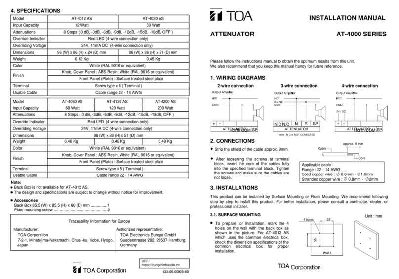
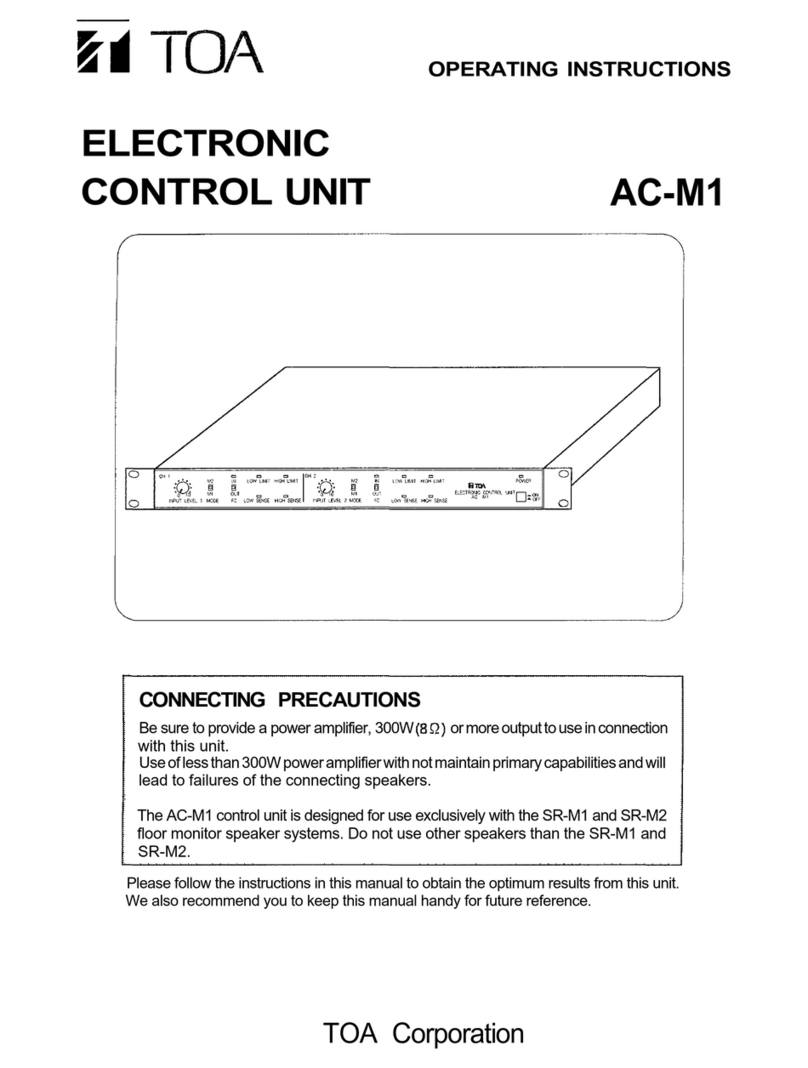
Toa AC-M1 User manual

Toa

Toa AC-M1 User manual

Toa IP-300XI User manual

Toa

Toa IP-300XI User manual

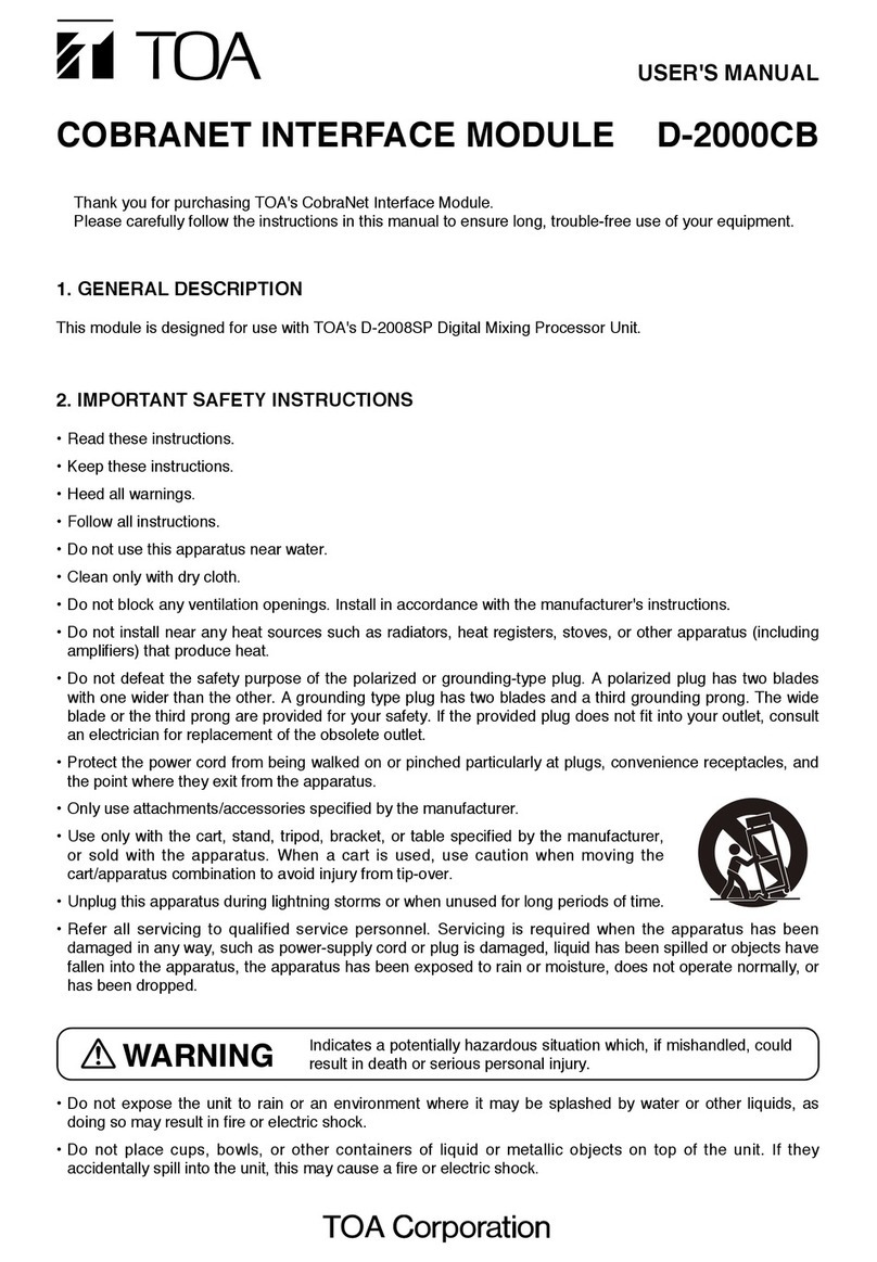
Toa COBRANET User manual

Toa

Toa COBRANET User manual

Toa AT-4012B-EB User manual

Toa

Toa AT-4012B-EB User manual

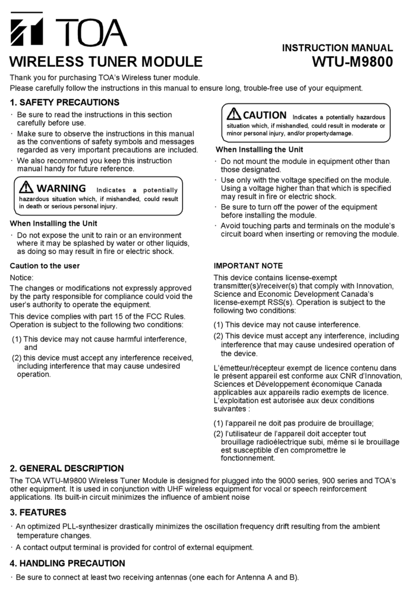
Toa WTU-M9800 User manual

Toa

Toa WTU-M9800 User manual

Toa AT-4000 Series User manual

Toa

Toa AT-4000 Series User manual

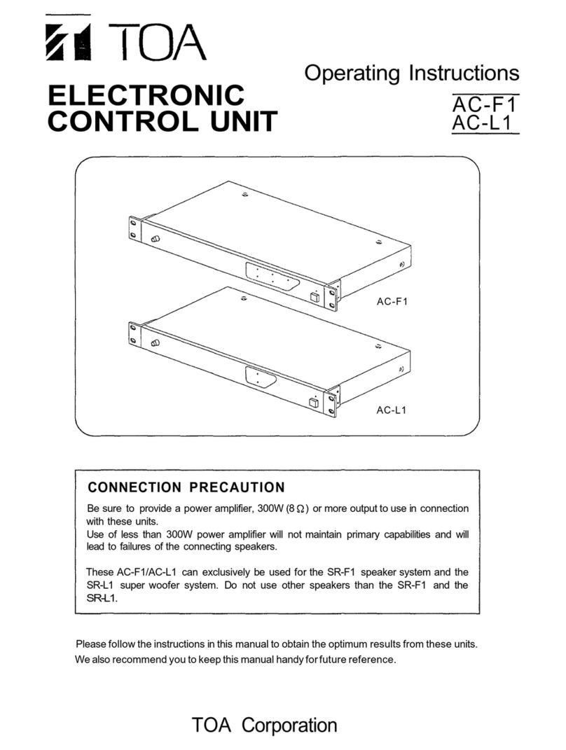
Toa AC-F1 User manual

Toa

Toa AC-F1 User manual

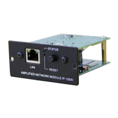
Toa IP-100XI User manual

Toa

Toa IP-100XI User manual

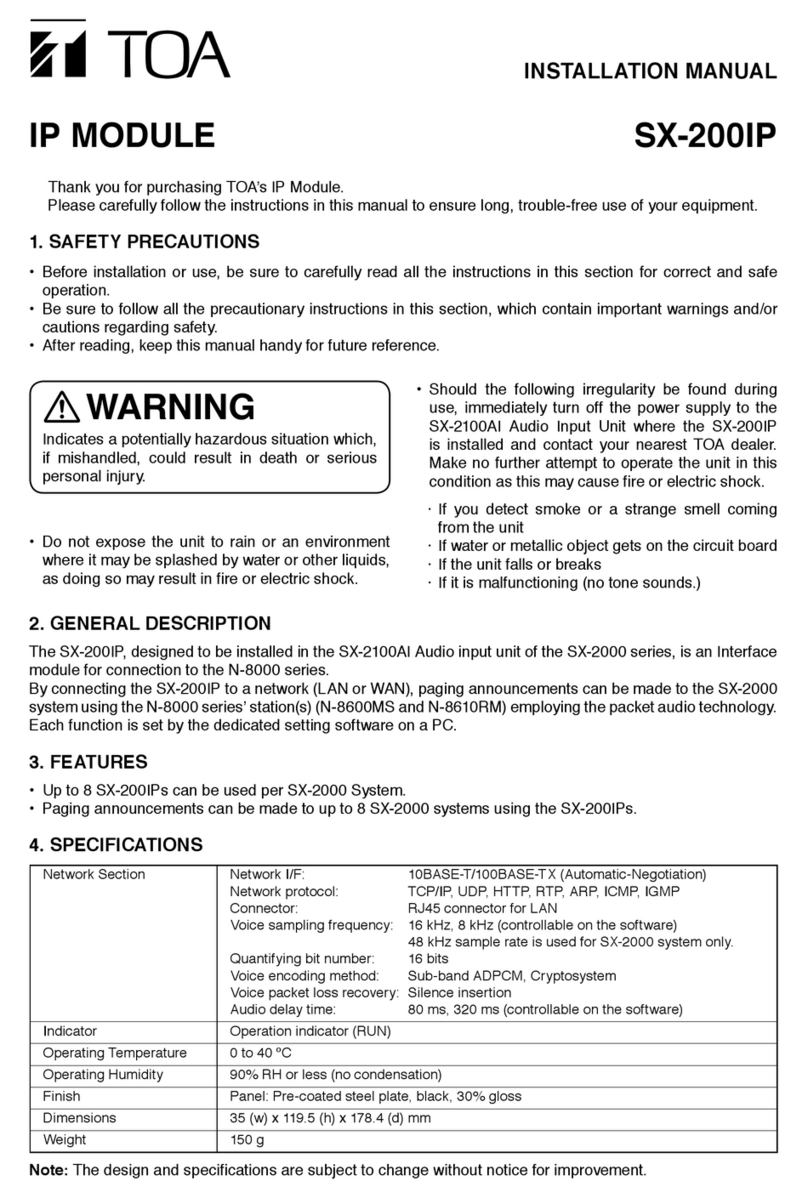
Toa SX-200IP User manual

Toa

Toa SX-200IP User manual

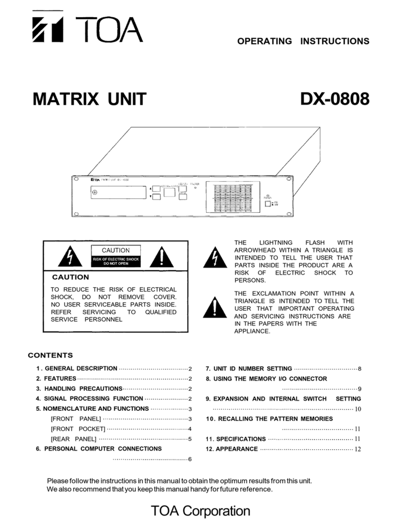
Toa DX-0808 User manual

Toa

Toa DX-0808 User manual

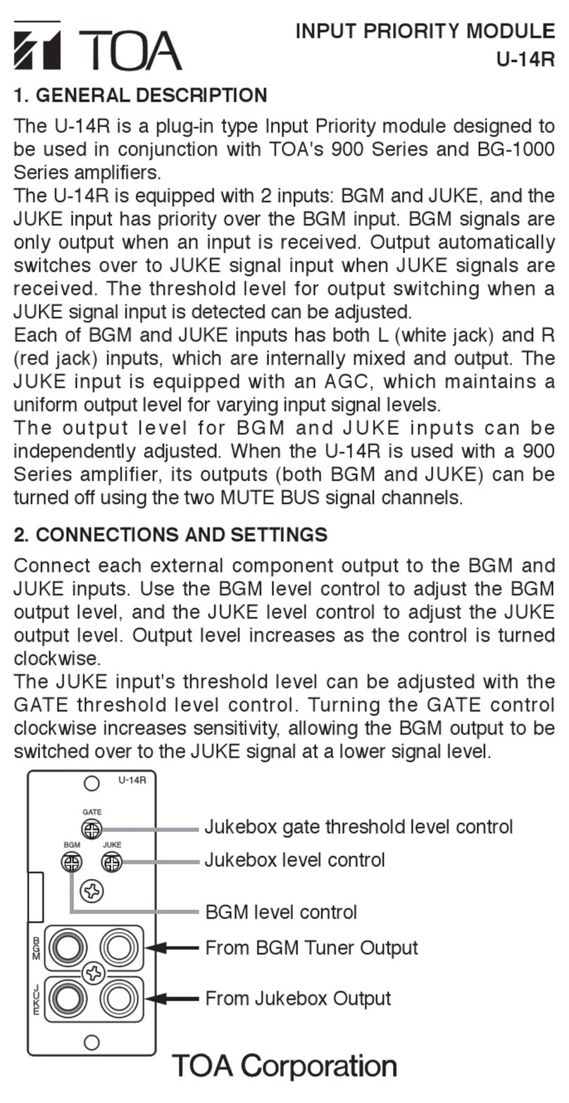
Toa U-14R User manual

Toa

Toa U-14R User manual

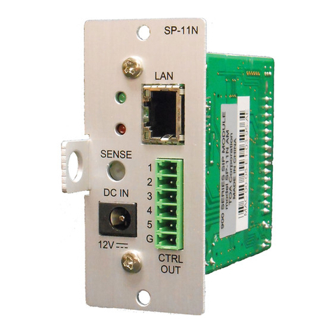
Toa SP-11N User manual

Toa

Toa SP-11N User manual

Toa AT-4060 AS User manual

Toa

Toa AT-4060 AS User manual

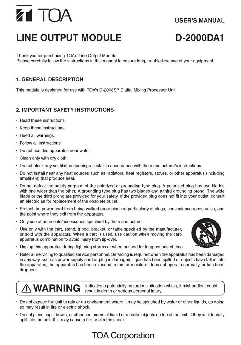
Toa D-2000DA1 User manual

Toa

Toa D-2000DA1 User manual

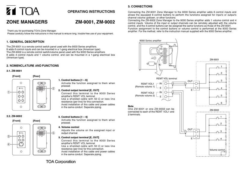
Toa ZM-9001 User manual

Toa

Toa ZM-9001 User manual

Popular Control Unit manuals by other brands

Pilz PNOZ m EF 16DI operating manual

Pilz

Pilz PNOZ m EF 16DI operating manual

Motion Control Engineering Motion 3000ES user guide

Motion Control Engineering

Motion Control Engineering Motion 3000ES user guide

KIESELMANN GEMBRA 5836 Operating	 instruction

KIESELMANN

KIESELMANN GEMBRA 5836 Operating instruction

Castles Technology UPT1000M user manual

Castles Technology

Castles Technology UPT1000M user manual

Vishay TSOP62 Series manual

Vishay

Vishay TSOP62 Series manual

Elkron T600 quick guide

Elkron

Elkron T600 quick guide

TBB power M12-400 user manual

TBB power

TBB power M12-400 user manual

Flowserve Valtek FlowTop V746 User instructions

Flowserve

Flowserve Valtek FlowTop V746 User instructions

Progres Agronic 4500 Assembly manual

Progres

Progres Agronic 4500 Assembly manual

Sony CCP-9000-C installation manual

Sony

Sony CCP-9000-C installation manual

brandoni EKOFLUX PI040 MAINTENANCE AND USE HANDBOOK

brandoni

brandoni EKOFLUX PI040 MAINTENANCE AND USE HANDBOOK

Definox VEOX SP 3 BODY Maintenance notice

Definox

Definox VEOX SP 3 BODY Maintenance notice

NiceRF SA818 manual

NiceRF

NiceRF SA818 manual

jablotron JA-114E quick start guide

jablotron

jablotron JA-114E quick start guide

CVS Controls 128PQC Series instruction manual

CVS Controls

CVS Controls 128PQC Series instruction manual

Pfeiffer Vacuum PM Z01 310 operating instructions

Pfeiffer Vacuum

Pfeiffer Vacuum PM Z01 310 operating instructions

Cypress CY4609 user guide

Cypress

Cypress CY4609 user guide

H3C NSQM1FWDFGC1 manual

H3C

H3C NSQM1FWDFGC1 manual

manuals.online logo
manuals.online logoBrands
  • About & Mission
  • Contact us
  • Privacy Policy
  • Terms and Conditions

Copyright 2025 Manuals.Online. All Rights Reserved.