POE power surge protector
network signal series Product
Manual
Do check the surge protector bef ore i nst al l ati on to prevent f r om
unnecessary i nj ury. I f t he surge protect or i s wi th any def ects, i t
shal l not be i nstal l ed.
Do use the sur ge protector s i n accor dance wi th the condi t i ons
speci f i ed i n the t echni cal tabl es. Exceedi ng t hei r l i mi ts may cause
damage t o t he prot ector i t sel f or even t o equi pment .
Do f ol l ow the rel evant standards and rul es when i nstal l i n
g. Thi s
surge protector must be i nstal l ed by qual i f i ed personnel who have
obt ai ned the r el evant certi f i cate befor e t he el ect r oni c equi pment t o be
pr ot ected.
Technical
Parameters
Model ZZRJ45(POE)/ZZRJ45-K(POE)
Number of protection roads 1 road or 24 road
Category Power Network
Nominal operating voltage Un 48V 5V
Maximum continuous
operating voltage Uc 60V 6V
Nominal discharge current
(8/20μS)In L-L:1kA L-L:300A
L-PE:2.5kA
Voltage protection level Up ≤150V(L-L)≤35V (L-L)
≤600V(L-PE) ≤300V(L-PE)
Response time tA ≤1ns
Transmission rate Vs 100/1000Mbps
Insertion loss aE≤0.5dB
Temperature range -40℃…+85℃
Protection line--- 1/2,3/6 data,4/5,
7/8 power
1/2,3/6 power 1/2,3/6,
4/5,7/8 data
Interface Type RJ45
Shell material Shielding metal
Dimensions 94x38x28mm 19 "rack
Degree of protection IP20
Sui t abl e LPZ1- LPZ3 Boundary, i nstal l ed i n a vari et y of
communi cati on l i ne + power suppl y, power suppl y, such as Ethernet,
wi r el ess br i dge, wi r el ess AP, networ k cameras, so t hat f r om
l i ght ni ng i nduced vo
l t age, vol t age f l uctuati ons i nt erf erence,
el ect rostati c di scharge, and l arge l oad start maj or damage t o t he
sur ge vol t age generated caused.
The i nt erf ace i n the f or m of RJ45, t he product i s di vi ded i nto
Fast and Gi gabi t POE. Thi s pr oduct has a t hr ough- f l ow capaci ty,
resi dual vol t age, f ast response, att enuati on, conveni ent
i nstal l ati on.
Scope of
application
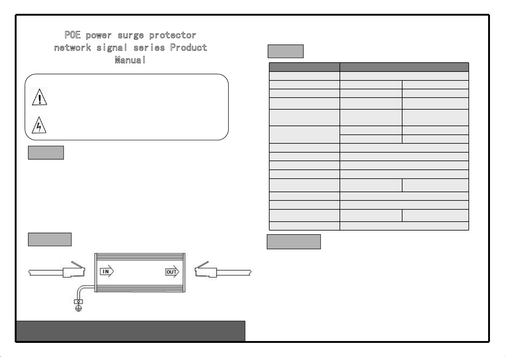
Installation
diagram Installation and
maintenance
1. POE power ser i es networ k si gnal sur ge prot ector can be i nstal l ed i n LPZ0- 1
area to be protect ed or di rectl y on t he devi ce ( or system) f ront end, f rom t he
devi ce ( or system) t o be protect ed when i nstal l i ng t he cl oser t he better.
2."I N" connects t he i ncomi ng l i ne, "OUT" connect s the prot ected devi ce ( or
syst em) . "L / +" connects t he power eart h l i ne or power suppl y l i ne, "N / - "
connects the power suppl y neutral or the power suppl y negati ve l i ne. When
i nst al l i ng, both ends of t he l i ne must be l ai d separatel y, not ti ed together t o
pr event f r om the secondary i nduct i on phenomenon.
3.The sur ge pr ot ector ground l i ne must be as shor t as possi bl e.
4.The sur ge pr ot ector does not r equi re l ong- term mai nt enance under t he
condi ti ons of i nstal l ati on, onl y routi ne mai ntenance. I f the si gnal transmi ssi on
i s wi th pr obl ems, r epl ace a new sur ge pr ot ector and si gnal tr ansmi ssi on back to
nor mal . I t i ndi cates that the sur ge pr ot ector has been damaged, need repai rment
or repl acement.
We are professional in manufacturing power surge protector, signal surge
protector, antenna-fed surge protector, lightning rod.


