C200HARDWARE
Instruction Manual C200 Part1 A1.doc optek Danulat GmbH •D-45356 Essen •Germany page 5
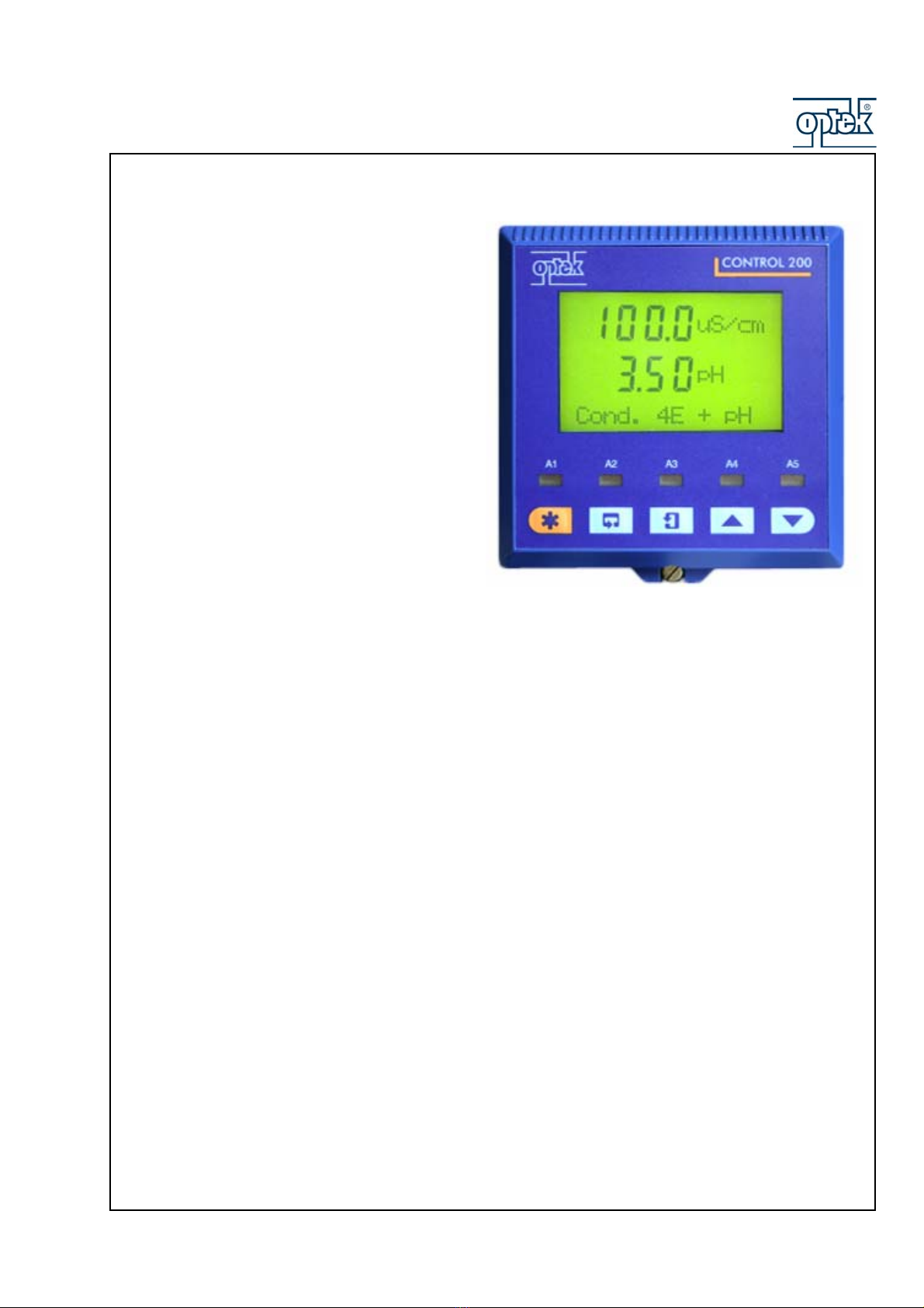
1 Converter description
CONTROL 200 is the all-round converter for
continuous monitoring and control of pH and
conductivity. The converter is intended to use with
either one or two of the following optek sensors:
PF12
(glass combination electrodes)
CF60
(6-electrode conductivity probe)
Functions of converter CONTROL 200:
The complete application spectrum is realized by converter CONTROL 200 in connection with different
inline sensors for pH and conductivity. The converters of CONTROL 200 series are available in different
configurations to be used with either one or two sensors (pH and /or 4-pole conductivity).
The backlit display has been designed to operate in all types of environments and shows both the measured
parameters and on a separate display line diagnostic and computed information. For conservation of
energy, the backlit can be set to switch off automatically after 60 s of inactivity.
Converter operation and programming are performed using five tactile membrane keys on the front panel.
Programmed functions are protected from unauthorized alteration by a five-digit security code.
Beside that the dual input CONTROL 200 incorporate a real time clock and a logbook which stores data
entries for alarm events, sensor errors, power failures and sensor calibrations.
Measurements for pH and conductivity can be done temperature compensated and the measured
temperature can be attached to an output signal as well. The converter allows the connection of resistance
thermometers like Pt 100, Pt1000 or Balco 3K which are mounted in the sensor and sense the medium
temperature directly in the pipe.
The pH converters can be connected to either a standard pH input or differential pH input. The dual input pH
provide advanced diagnostic facilities and detects sensor breakages as they occur. Beside that low glass
impedance and out-of-sample/broken cable warnings are given as well. Differential pH input is designed for
use with pH electrode systems that incorporate a solution earth (ground) connection. The measuring
electrode and reference electrode signals are measured separately using two, high impedance amplifiers
and compared with the solution earth potential. The difference between the results is the value used for the
pH measurement. Furthermore the pH converters incorporate the most common buffer tables, e.g. ABB,
DIN, Merck, NIST and US Tech for automatic 1 or 2 points calibration to provide a fully ease of use.
Needless to mention that calibration can be done as well user defined.
The conductivity converters can run probes with different cell constants and provide extremely broad
measuring ranges up to 1.999 mS/cm. By means of preset (NaOH, NaCl, HCl, H2SO4, H3PO4) or user
defined 6-point concentration curves the measured conductivity can be converted directly into concentration
of the component to be measured.