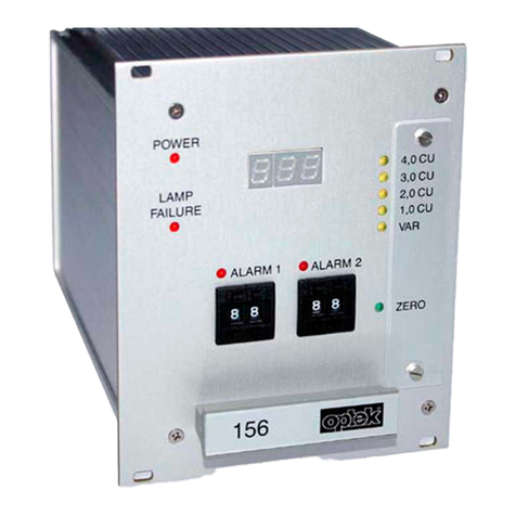
Optek PROFIBUS C4151 User manual

Instruction Manual
optek PROFIBUS®PA
optek-Manual--1004-1010-02--ProfibusPA-US-2017-06-23
PN: 1004-1010-02 (-52)
For converters:
C4151
C4251
C4252
C4353
C4452
HC4351
HC4452
optek-Danulat GmbH
Emscherbruchallee 2
45356 Essen
Phone: +49-(0)201-63409-0
E-Mail: info@optek.de
Internet: www.optek.com

Preface
optek-Manual--1004-1010-02--ProfibusPA-US-2017-06-23
www.optek.com
Preface
This instruction manual is written to assist the user in proper procedures for
trouble-free operation.
Itis explicitlypointed out thatoptek-Danulat GmbH assumes no responsibilityfor
loss or damage caused due to improper use of this instruction manual or
products described herein.
This manual is protected by copyright. However, the user may produce copies
and translations if required for correct operation of the products.
On request, this manual is available in other languages as well as in digital
format (Acrobat®Reader 7.0 required).
Our products are being continuously improved. Technical data is subject to
change without notice.
Essen, October 2016

Table of contents
- I -
optek-Manual--1004-1010-02--ProfibusPA-US-2017-06-23
www.optek.com
Table of contents
Preface
1 Using the instruction manual .................................................................................................1
1.1 Validity of the instruction manual .........................................................................................1
1.2 Pictograms and signal words ...............................................................................................3
2 Intended use .............................................................................................................................4
3 Safety ........................................................................................................................................5
3.1 General safety instructions...................................................................................................5
3.2 Safety instructions for works on electrical equipment...........................................................6
4 Description PROFIBUS® .........................................................................................................7
5 Description optek Control 4000 / Haze Control bus interface ...........................................10
5.1 Technical data PROFIBUS® PA interface..........................................................................13
5.2 Converter front view...........................................................................................................14
5.3 Rear view converter C4151................................................................................................15
5.4 Rear view converter C4251................................................................................................16
5.5 Rear view converter C4252................................................................................................17
5.6 Rear view converter C4352................................................................................................18
5.7 Rear view converter C4452................................................................................................19
5.8 Rear view HC4351 converter .............................................................................................20
5.9 Rear view HC4452 converter .............................................................................................21
5.10 Connecting the sensors .....................................................................................................22
5.11 PROFIBUS® PA interface..................................................................................................23
6 Addressing .............................................................................................................................24
6.1 Overview addressing..........................................................................................................24
6.2 Addressing methods ..........................................................................................................24
6.3 Addressing via the master control system..........................................................................24

Table of contents
- II -
optek-Manual--1004-1010-02--ProfibusPA-US-2017-06-23
www.optek.com
7 Specifications ........................................................................................................................26
7.1 Physical Block....................................................................................................................27
7.2 Analyzer TB for measuring results M01–M04.....................................................................31
7.3 AI FB for measuring results M01–M04...............................................................................32
7.4 Relay TB............................................................................................................................33
7.5 DI FB relay 1 to 4...............................................................................................................34
7.6 AO TB................................................................................................................................35
7.7 AO FB for mA-In1 and mA-In2 ...........................................................................................36
7.8 Status TB...........................................................................................................................38
7.9 Device Spec. Data structures.............................................................................................41
7.10 Diagnosis...........................................................................................................................42
7.11 Condensed status..............................................................................................................44
7.12 Number display format.......................................................................................................45
8 Software ..................................................................................................................................46
8.1 GSD file .............................................................................................................................46
8.2 EDD file .............................................................................................................................46
8.3 FDT / DTM technology.......................................................................................................46
9 Appendix ................................................................................................................................47
9.1 Addressing of the optek PROFIBUS® PA interface............................................................48
9.1.1 Addressing of the optek PROFIBUS® PA interface with communication
processor CP5512 ...................................................................................................50
9.1.2 Addressing of the optek PROFIBUS® PA interface with interface card
"Softing PROFlusb" .................................................................................................52
9.2 PROFIBUS® PA certificate ................................................................................................56
9.3 DTM certificate...................................................................................................................57
10 EU declaration of conformity ................................................................................................59
11 Contacts .................................................................................................................................60

Using the instruction manual
- 1 -
optek-Manual--1004-1010-02--ProfibusPA-US-2017-06-23
www.optek.com
1 Using the instruction manual
1.1 Validity of the instruction manual
This instruction manual is valid for optek PROFIBUS®converters C4151,
C4251, C4252, C4352, C4452, HC4351 and HC4452. It contains specific
information on the PROFIBUS®PA interface (Process Fieldbus - Process
Automation).
Information regarding the installation and operation of the converter is provided
in the supplied standard instruction manual of the corresponding converter.
To differentiate PROFIBUS®converters from standard converters by name, the
2 (for 2mA- and 7 remote inputs) in the model number (H)C4X2Z (X=1–4,
Z=1–2) was replaced with a 5.
The model number of PROFIBUS®converters is set up as follows:
Converter C4252 is thus a C4000 series converter with inputs for two sensors
as well as a PROFIBUS®PA interface and two lamp outputs.
The model number indicates the hardware configuration of your converter.
Therefore, the following combinations of instruction manuals apply:
Tab. 1 Instruction manual combinations overview
PROFIBUS®
converter:
Instruction manuals Remark:
Amendment with respect to
standard instruction manual
Additional manual Standard of
C4151 PROFIBUS®PA C4121 Instead of mA- and remote inputs,
there is a PROFIBUS®PA
interface.
Thus, chapters 8.6 "Connecting
the mA-inputs" and 8.8
"Connection Remote In" do not
apply to the PROFIBUS®PA
version.
C4251 PROFIBUS®PA C4221
C4252 PROFIBUS®PA C4222
C4352 PROFIBUS®PA C4322
C4452 PROFIBUS®PA C4422
HC4351 PROFIBUS®PA HC4321
HC4452 PROFIBUS®PA HC4422
model number: (H)C4 _ 5 _
Number of
inputs for
optek-sensors The "5" stands for the
PROFIBUS®input.
Number of
lamp outputs

Using the instruction manual
- 2 -
optek-Manual--1004-1010-02--ProfibusPA-US-2017-06-23
www.optek.com
For all works, observe this instruction manual as well as the corresponding
standard instruction manual. If the converter is not used as described in these
instruction manuals, your safety and the converter function could be affected.
To keep up reliability of the product, enhance its life cycle and avoid down times,
you have to follow the instructions in the manuals.
Furthermore, please follow the existing accident prevention and environmental
protection instructions, as well as recognized technical instructions for safe and
professional working.

Using the instruction manual
- 3 -
optek-Manual--1004-1010-02--ProfibusPA-US-2017-06-23
www.optek.com
1.2 Pictograms and signal words
Important information in this instruction manual is marked with the following
pictograms:
Danger!
This pictogram indicates immediate danger to life and health of persons.
The text next to the symbol gives information on how to avoid bodily injuries.
If the possible cause of risk can be specified, the corresponding pictogram
precedes instructions:
Danger!
Electrical voltage.
This pictogram indicates danger due to electrical voltage.
Caution!
This pictogram indicates information on how to avoid material damage.
Note!
This pictogram indicates instructional or general advice.
Pictograms on the
converter
The following pictogram is on the back of the converter.
It indicates possible and unapparent dangers.
Read this instruction manual prior to initial commissioning.

Intended use
- 4 -
optek-Manual--1004-1010-02--ProfibusPA-US-2017-06-23
www.optek.com
2 Intended use
The converter is to be used exclusively for optek sensor assemblies according
to the technical data.
In combination with inline sensors for turbidity, concentration, color and UV
absorption, the converter is used for displaying and processing measuring
results.
The converter may only be interfaced with sensors listed in the "Technical data"
chapter of the corresponding instruction manuals.
The converter is to be installed in closed control cabinets with external switch,
which allows the user to disconnect power. Please refer to the "Technical data"
chapter.
This converter is not intended for use in hazardous areas.
Unauthorized constructional changes, additional fittings or modifications
regarding the converter as well as tampering with or changing its software are
prohibited.
The manufacturer is not liable for damage resulting from use contrary to the
intended use.
Following this instruction manual is part of the intended use.
The content of all serial number plates on optek products is model-specific and
refers to the time of delivery.

Safety
- 5 -
optek-Manual--1004-1010-02--ProfibusPA-US-2017-06-23
www.optek.com
3Safety
3.1 General safety instructions
Only operate the converter when free from defects and in accordance with the
instructions provided in this manual.
Read this instruction manual prior to initial commissioning. This applies
especially to persons only operating the converter occasionally, such as
maintenance staff.
Observe all safety and information labels on the product and keep them in
readable condition.
Inspect the product for signs of physical damage. Report any damage
immediately and do not commission the product until corrective actions have
been taken.
After maintenance and repair, proper function as well as the fulfillment of the
safety requirements and testing must be guaranteed.
Protect the converter from impacts causing corrosion or preventing components
from working properly.
Have faulty parts of the measuring system replaced immediately.
Spare parts must comply with the technical requirements defined by optek. This
is always guaranteed when using original spare parts.
For maintenance and repair activities, attach a warning sign to the external
release device to prevent re-commissioning of the converter.
When malfunctioning, take the product out of operation. Have the malfunctions
repaired immediately by a qualified electrician.
The safety instructions are to be supplemented with the current national
regulations on accident prevention.

Safety
- 6 -
optek-Manual--1004-1010-02--ProfibusPA-US-2017-06-23
www.optek.com
3.2 Safety instructions for works on electrical equipment
Work on electrical equipment has to be carried out by qualified electricians only.
The power line connection of the converter must be specified correctly to
prevent overload.
Disconnect the voltage supply before connecting the power line. Only connect
the power line when voltage-free. Do not use the terminal socket for release
since no first-to-mate last-to-break protective ground contact is provided.
Do not work on live active parts of the electrical equipment. When working on
the electrical equipment, observe the following safety regulations:
1. Switch voltage-free.
2. Protect against re-commissioning.
3. Check if voltage-free.
4. Cover live parts.
5. Earth and short-circuit.
In case of faults in the power supply, disconnect the converter immediately.
In case of a short-circuit, there is a danger of sparking and fire.
Use only original fuses with specified current and triggering characteristics!
When a fuse has to be exchanged, first try to detect the cause and clear the fault
before exchanging the fuse.
When work on live parts is necessary, use insulated tools only.

Description PROFIBUS®
- 7 -
optek-Manual--1004-1010-02--ProfibusPA-US-2017-06-23
www.optek.com
4 Description PROFIBUS®
Introduction Constant availability of information is one of the most important characteristics
of today's corporate communication. In the fields of production processes
(manufacturing, process and building automation), PROFIBUS®provides the
basis for networking.
PROFIBUS®is a digital communication system between the control system and
the measuring and control elements. It is the leading open fieldbus system in
Europe.
PROFIBUS®interconnects decentral field devices via one cable and integrates
them into a control system. Here, "real" process values are transferred instead
of mA-signals as in the 4–20 mA-technology.
In the following, the variants with their basic characteristics are listed:
PROFIBUS®DP
(Decentralized
Periphery)
This variant was optimized for manufacturing automation.
The transfer technology is a RS485 standard with a transfer rate of 12 Mbit/s. It
features a short response time, good diagnosis possibilities, noise-immune
transfer and easy handling.
PROFIBUS®PA
(Process Automation) This version was especially developed for use in process automation. The
transfer technology is MBP with a transfer rate of 31.25 kbit/s. Use in hazardous
locations is possible.
There are two basic PROFIBUS®device types:
Master The master controls data traffic on the bus (e. g. programmable logic controller).
It sends messages without external prompts and is also referred to as an "active
station".
Slave Slaves are peripherals such as valves, drives, converters and analysis devices.
They shall only acknowledge received messages or transfer messages to the
master after master request. This is why they are also referred to as "passive
stations".
To keep up communication under PROFIBUS®, software protocols are
generated. The DP protocol is used for the transport layer between master and
slave. It determines type and speed of data interchange and defines the transfer
protocol of the PROFIBUS®system.
There are two DP master classes:
DP class 1 master Controller of a DP system (e. g. controls, PLC, …).
DP class 2 master Allows loading programs in controls, diagnosis, parameterization of DP slaves.
A PROFIBUS®network must always include at least one class 1 master.

Description PROFIBUS®
- 8 -
optek-Manual--1004-1010-02--ProfibusPA-US-2017-06-23
www.optek.com
The figure below shows the principle structure of a PROFIBUS®system. All
devices are connected in a bus structure (line). Up to 32 stations can be
interconnected in one segment. At the beginning and end, each PROFIBUS®
segment must be terminated.
Fig. 1 Principle structure of a PROFIBUS®system
A DP/PA segment coupler or a DP/PA link allows the connection of
PROFIBUS®DP and PROFIBUS®PA. A PROFIBUS®PA segment is always a
subsegment of a DP segment.
DP/PA segment
coupler A DP/PA segment coupler is a signal converter which adjusts RS485 signals to
the MBP signal level and vice versa. It does not have an individual bus address
and is transparent for the DP master stations. Therefore, only certain bit rates
are possible in the DP segment (e. g. 45.45 kbit/s).
DP/PA link The DP/PA link has a slave station address over which the DP master accesses
the PA segment. In the DP segment, an independent bit rate of 12 Mbit/s
maximum is possible.

Description PROFIBUS®
- 9 -
optek-Manual--1004-1010-02--ProfibusPA-US-2017-06-23
www.optek.com
The PROFIBUS®PA allows cyclic as well as acyclic data transfer. Cyclic
services allow transfer of measuring results. They belong to the DP class 1
master and use protocol DP-V0.
Acyclic servicesservefor deviceparameterization,remotesupport maintenance
and diagnosis during operation. They belong to the DP class 2 master and use
protocol DP-V1.
Fig. 2 Cyclic and acyclic data transfer

Description optek Control 4000 / Haze Control bus interface
- 10 -
optek-Manual--1004-1010-02--ProfibusPA-US-2017-06-23
www.optek.com
5 Description optek Control 4000 / Haze Control bus
interface
To allow the easiest possible commissioning of the C4000 converter and the
Haze Control at the bus, the reliable concept of parameterization via parameter
sets was maintained in great parts. Up to eight parameter sets each can be
stored on the converter with a product number with product name for that
purpose.
For comfortable handling even of complex parameter sets (e. g. complex
mathematical operations), the well-known PC-Transfer Advanced software is
used for the Control 4000.
Thus, almost allinternalparameters canbe changed when changing the product
number. The product number can be changed locally or via access to an
individual register via bus.
Even complex parameter changes, such as the exchange of the mathematical
operations of several input signals or the exchange of the linearization function
for a simple operation in the control system, are therefore possible. It is not
necessary to reboot the converter or bus segment.
The structure with up to four independent definable measuring results to each of
which a name and a text for designating the unit can be assigned was adapted
as well.
The four measuring results also play a central role for mapping on the bus: To
each of these measuring results, a transducer block and an analog function
block are assigned according to the PROFIBUS®PA profile specification.
Therefore, in cyclic data traffic, these four measuring results can be read,
together with the corresponding status information.
For each measuring result, apart from the limit values without bus connection,
there are four additional limit values in the cyclically transferred status
information. There, the informationregarding qualityof the measuring result with
respect to malfunctions of the converter or bus interface is provided as well.
The four status are mapped on the four evaluation levels
• good
•uncertain
• local override and
•bad
according to the condensed status.

Description optek Control 4000 / Haze Control bus interface
- 11 -
optek-Manual--1004-1010-02--ProfibusPA-US-2017-06-23
www.optek.com
Since the signal loss state is admitted for some applications but indicates
technical malfunctions in others, the user can change the assignment to
uncertain or bad.
The functionality defined with parameter sets can be queried in acyclic data
traffic with the standard parameters of the function blocks. Thus, e.g. set limits
of the measuring range and the names of the units can be read by the control
system.
Apart from the measuring results, in cyclic traffic, the switching status of the four
relay outputs are available as well. They are arranged in a shared digital input
block.
To send analog signals from control to converter, there are two analog output
blocks. In the converter, these are used like the mA-inputs available for
converter models (H)C4X2Z (X=1–4, Z=1–2).
Malfunctions of converter or bus interface can be displayed with the
PROFIBUS®diagnosis mechanism. They are signaled in the
manufacturer-specific diagnosis.
For some parameters (e. g. signal loss), the user can choose if these shall be
displayed in the manufacturer-specific diagnosis.
Further detailed information on the state of the converter can be read out of the
optek-specific status transducer block. Here, data of lamp and detector monitor
can be called aswell as sensorinformation and alist ofavailable product names.
A writable parameter defines which channels are displayed. In case an error is
signaled, the number of the error message, such as displayed on the converter
display, can be read out as well.

Description optek Control 4000 / Haze Control bus interface
- 12 -
optek-Manual--1004-1010-02--ProfibusPA-US-2017-06-23
www.optek.com
The following figure shows the PROFIBUS®PA interface for the C4000 and the
Haze Control converter according to PROFIBUS®PA profile 3.01 with
amendment 2: Analyzer.
Fig. 3 PROFIBUS®PA interface for C4000 and Haze Control converter
Numbers stand for:
PB = physical block
TB = transducer block
FB = function block
AO = analog output block
AI = analog input block
DI = digital input
PD IN X = detector input A-D
MW 1-4 = measuring result 1-4

Description optek Control 4000 / Haze Control bus interface
- 13 -
optek-Manual--1004-1010-02--ProfibusPA-US-2017-06-23
www.optek.com
5.1 Technical data PROFIBUS®PA interface
Tab. 2 Technical data PROFIBUS®PA interface
Physical: IEC 61158-2
31.25 kbit/s
voltage mode
Connection: polarity-independent
Voltage range: 9…32 V
Background current: 18 mA
Galvanic separation: function separation
Intrinsic safety: no
ID: 0x0BF3
Address range: 3 to 126
delivery state 126
Set_Slave_Adr. of master
Device profile: PROFIBUS®PA profile, version 3.01 with amendment 2
Block structure:
1 PB
4 AI with 1 TB each
4 DI with 1 TB
2 AO with 1 TB
1 status TB (device-specific)

Description optek Control 4000 / Haze Control bus interface
- 14 -
optek-Manual--1004-1010-02--ProfibusPA-US-2017-06-23
www.optek.com
5.2 Converter front view
Fig. 4 Front panel PROFIBUS®PA converter C4000 and Haze Control
Numbers stand for:
1. LED (flashes red), indicates lamp failure or system failure
2. LED (yellow), switch indicator for alarm 3 when a value exceeds or falls
below a limit value
3. LED (yellow), switch indicator for alarm 2 when a value exceeds or falls
below a limit value
4. LED (yellow), switch indicator for alarm 1 when a value exceeds or falls
below a limit value
5. LED (green), indicates readiness for operation
6. Numerical keyboard (single assignment)
7. Connection for RS-232 (control-connect cable)
8. ENTER key (confirmation of entries)
9. Cursor key (moving in the menus and entries)
10. CLEAR key (rejecting entries, returning to previous menu)
11. Display
1234
7
6
5
8910
11
1234
7
6
5
8910
11

Description optek Control 4000 / Haze Control bus interface
- 15 -
optek-Manual--1004-1010-02--ProfibusPA-US-2017-06-23
www.optek.com
5.3 Rear view converter C4151
Fig. 5 Rear view converter C4151
Numbers stand for:
1. Detector input A (only for optek-sensors)
2. -
3. PROFIBUS®PA interface
4. mA-output 1, mA-output 2 (0/4–20 mA)
5. -
6. Lamp output E (only for optek-sensors)
7. -
8. Relay outputs 1,2,3 for limit values orsystem status feedback,system relay
(enabled)
9. -
10. Fuse I 115/230 V AC T 1.6 A (option 24 V AC/DC: T 3.15 A)
11. Fuse II 115/230 V AC T 1.6 A (option 24 V AC/DC: T 3.15 A)
12. Power supply (fixed)
13. Selector switch for voltage (preset 230 V AC) -
(does not apply for a 24 V AC/DC version)
14. Equipotential bonding (in the non-ex-proof version, only necessary in
extreme EMC requirements)
15. ON / OFF switch
16. -
17. Detector input C (inactive)
19 20 21
V DC
6
230V
DETECTOR INPUTS
[C]
3
4
5
3
4
5
[D]
OPTEK - DANULAT
M6
PA L
PE
N
R6
R8
RR
R7
R2
R5
R4
R3
R1
MADE IN GERMANY
36
39
37
38
32
34
35
33
31
15
18
16
17
11
13
14
12
10
6
7
6
7
LAMP [F]
7
7
6
V DC
acc. to
length
cable
acc. to
cable
length
DETECTOR INPUTS
[A]
5
2
1
[B]
5
2
1
REMOTE IN
115 / 230 V, 50 / 60 Hz, 50 VA
115 / 230 V, T 1,6 A
!
24 V DC
0 / 4 - 20 mA
OUT 1, 2
RELAY OUT
24 V AC / DC
51
53
54
52
40
42
43
41
46
47
45
44
LAMP [E]
OUT 3, 4
14
6
8
101112131415
17
3

Description optek Control 4000 / Haze Control bus interface
- 16 -
optek-Manual--1004-1010-02--ProfibusPA-US-2017-06-23
www.optek.com
5.4 Rear view converter C4251
Fig. 6 Rear view converter C4251
Numbers stand for:
1. Detector input A (only for optek-sensors)
2. -
3. PROFIBUS®PA interface
4. mA-output 1, mA-output 2 (0/4–20 mA)
5. -
6. Lamp output E (only for optek-sensors)
7. -
8. Relay outputs 1,2,3 for limit values orsystem status feedback,system relay
(enabled)
9. -
10. Fuse I 115/230 V AC T 1.6 A (option 24 V AC/DC: T 3.15 A)
11. Fuse II 115/230 V AC T 1.6 A (option 24 V AC/DC: T 3.15 A)
12. Power supply (fixed)
13. Selector switch for voltage (preset 230 V AC) -
(does not apply for a 24 V AC/DC version)
14. Equipotential bonding (in the non-ex-proof version, only necessary in
extreme EMC requirements)
15. ON / OFF switch
16. -
17. Detector input C (only for optek-sensors)
19 20 21
V DC
6
230V
DETECTOR INPUTS
[C]
3
4
5
3
4
5
[D]
OPTEK - DANULAT
M6
PA L
PE
N
R6
R8
RR
R7
R2
R5
R4
R3
R1
MADE IN GERMANY
36
39
37
38
32
34
35
33
31
15
18
16
17
11
13
14
12
10
6
7
6
7
LAMP [F]
7
7
6
V DC
acc. to
length
cable
acc. to
cable
length
DETECTOR INPUTS
[A]
5
2
1
[B]
5
2
1
REMOTE IN
115 / 230 V, 50 / 60 Hz, 50 VA
115 / 230 V, T 1,6 A
!
24 V DC
0 / 4 - 20 mA
OUT 1, 2
RELAY OUT
24 V AC / DC
51
53
54
52
40
42
43
41
46
47
45
44
LAMP [E]
OUT 3, 4
14
6
8
10111213141517
3
This manual suits for next models
6
Table of contents
Other Optek Media Converter manuals
Popular Media Converter manuals by other brands

Mhdt Labs
Mhdt Labs Stockholm instruction manual

GSS
GSS PHIS 1000 S Assembly instruction

CTC Union
CTC Union FRM220-100M user manual

Idex
Idex LIQUID CONTROLS HML210 Installation & operation manual

Pixel Magic Systems
Pixel Magic Systems plasma Enhancer PE1000 PRO Brochure & specs

Sonnet
Sonnet Hermes owner's manual