Optex Gen-IDCAM User manual

1 BEFORE INSTALLATION
Warning
Failure to follow the
instructions provided
and improper handling
may cause death or
serious injury.
Do not touch the unit base or power terminals of the product with a wet hand. (Also, if the product is wet
after rain, do not touch it.) It may cause electric shock.
Never attempt to disassemble or repair the product. It may cause fire or damage to the devices.
[Handling of Batteries]
Fire, explosion and severe burn hazard. Do not recharge, short circuit, crush, disassemble, heat above 100°C,
Incinerate, or expose contents to water. Do not solder directly to the cell.
Caution
Failure to follow the
instructions provided
and improper handling
may cause injury and/or
property damage.
Do not pour water over the product. The water may enter and may cause damage to the devices.
Clean and check the product periodically for safe use. If any problem is found, do not attempt to use the product
as it is and inform your installer.
If you do not use the product for a long period of time, remove the battery. Keep it in a cool, dark area.
Dispose batteries according to local regulations.
This symbol indicates prohibition. The specific prohibited action is provided in and/or around the figure.
This symbol requires an action or gives an instruction.
GEN-IDCAM is a ZigBee passive infrared (PIR) motion sensor camera with pet-immune function. It is capable of sending wireless signals and captured
images (picture quality of up to 640 x 480 pixels) to the coordinator in the ZigBee network upon movement detection.
The PIR Camera is designed to give a typical detection range of 12 meters when mounted at 2 meters above ground. It has a pet-immune range of 7
meters and will not trigger false alarm from your household pets within this distance.
The PIR Camera utilizes ZigBee technology for wireless signal transmission. ZigBee is a wireless communication protocol that is reliable and has low
power consumption and high transmission efficiency. Based on the IEEE802.15.4 standard, ZigBee allows a large amount of devices to be included in a
network and coordinated for data exchange and signal transmission
The PIR Camera serves as an end device in the ZigBee network. It can be included in the ZigBee network to transmit signal upon activation, but cannot
permit any other ZigBee device to join the network through the PIR.
2 PARTS IDENTIFICATION
1. Flash LED
The Flash LED delivers sufficient light for image capture under low lighting condition.
Both the Flash LED and the Blue LED will flash once when the Function Button is pressed for 10 seconds to indicate the PIR Camera has been reset.
2. Blue LED/Function Button
LED Indication
The Blue LED lights up in the following conditions.
The Blue LED flash once every 20 minutes
The PIR Camera has lost connection to its current ZigBee network.
The Blue LED lights up for 30 seconds:
The PIR Camera is warming up when fault(s) exists in the PIR Camera.
The Blue LED flashes twice quickly:
The PIR Camera has successfully joined a ZigBee network after factory reset.
The Blue LED lights up for 2 seconds under normal operation:
The PIR Camera has detected a movement when fault(s) exists in the PIR Camera.
The Blue LED flashes rapidly
PIR Camera is transmitting pictures to the coordinator of the ZigBee network when fault(s) exists in the PIR
Camera.
The Blue LED and Flash LED flash once
PIR Camera has been reset.
Function Button Usage
To send a supervision signal, press the button once.
To reset the PIR Camera, press and hold the button for 10 seconds. Release the
button when both the Flash LED and the Blue LED flash once
3. IR Sensor
The sensor is intended to detect moving objects.
4. PIR Camera Lens
5. Battery Compartment Cover
6. Battery Compartment Screw
7. Tamper Switch
When the PIR Camera is properly installed, the Tamper switch will be activated when the PIR
Camera is removed from mounting surface, or its cover opened. The Tamper switch is restored
when the PIR Camera is installed properly and its cover secured.
8. Battery Compartment
9. Jumper Switch (JP2)
I
NSTAL
L
ATION
INSTRUCTIONS
5925
40
-
0

Jumper On: After transmitting for a detected movement, any further movement detection will transmit the event code again (and the captured images)
(default).
Jumper Off: PIR Camera has a “sleep time” of approximately 1 minute to conserve power.
3 FEATURES
IMAGE CAPTURE
When the alarm system is armed, the PIR Camera will capture 3 or 6 alarm images in 640 x 480 or 320 x 240 resolutions (programmable from control
panel) upon movement detection. You can also manually request the PIR Camera to take a picture through CIE. The captured images will be transferred
to ZigBee coordinator or CIE for user to view.
WARM UP PERIOD
When the ZigBee system enters arm mode, or when PIR Camera is put into Test Mode, the PIR Camera will warm up for 30 seconds. Do not trigger the
PIR Camera during the 30-second warm up period. If the PIR Camera is under low battery or tamper opened condition, the Blue LED will light up during
the warm up period.
SLEEP TIMER
When Jumper Switch 2 is set to Off, the PIR Camera has a “sleep time” of approximately 1 minute to conserve power. After transmitting for a detected
movement, the PIR Camera will not retransmit for 1 minute. Any detected movement during this period will reset the sleep time to 1 minute. Continuous
movement in front of the PIR Camera will therefore not exhaust the battery.
BATTERY AND LOW BATTERY DETECTION
The PIR Camera uses two 1.5V “AA” Lithium batteries in series connection as its power source. Remove the Battery Compartment Cover and insert
the batteries to activate the PIR Camera.
The PIR Camera features Low Battery Detection function. When the battery voltage is low, the PIR Camera will transmit Low Battery signal to the
coordinator in ZigBee network. If movement is detected under Low Battery condition, the Blue LED will light up for 2 seconds.
When changing battery, after removing the old battery, press the Tamper Switch or the Function Button twice to fully discharge before inserting new
batteries
TAMPER PROTECTION
The PIR Camera is protected by a tamper switch which is compressed when the PIR Camera is properly installed. When the PIR Camera is removed
from mounted surface or its cover opened, the tamper switch will be activated and the PIR Camera will send a tamper open signal to the ZigBee network
coordinator or system control panel to remind the user of the condition. If movement is detected when the tamper switch is open, the Blue LED will light
up for 2 seconds.
PIR Camera will not detect the status of the tamper switch within 5 minutes of inserting battery.
If the Tamper Switch is triggered during this 5-minute non-detection period, the PIR Camera will transmit a tamper status signal to the ZigBee
network coordinator or system control panel immediately after the 5-minute non-detection period.
When the tamper switch is compressed, Factory Resetting the PIR Camera is disabled.
SUPERVISION
The PIR Camera will transmit a supervision signal to report its condition regularly according to user setting. The factory default interval is 30 minutes. The
user can also press the Function Button once to transmit a supervision signal manually.
TEST MODE
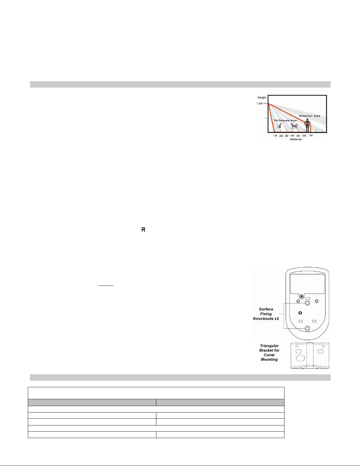
Test mode is for you to check the PIR camera’s detection range (not shooting coverage).
To enter Test mode, press and hold the Function button over 3 seconds and release the button to enter the Test mode for 3 minutes.
The PIR camera will warm up for 30 seconds. Please do not trigger the Camera during this warming-up period.
After the warm-up period, you can trigger PIR camera to check IR detection range. If PIR camera is triggered, the Blue LED will light up for 2
seconds.
4 ZigBee NETWORK SETUP
ZigBee DEVICE GUIDELINE
ZigBee is a wireless communication protocol that is reliable, has low power consumption and has high transmission efficiency. Based on the
IEEE802.15.4 standard, ZigBee allows a large amount of devices to be included in a network and coordinated for data exchange and signal
transmission.
Due to the fundamental structure of ZigBee network, ZigBee device will actively seek and join network after powering on. Since performing a task in
connecting network may consume some power, it is required to follow the instructions to avoid draining battery of a ZigBee device
Ensure your ZigBee network router or coordinator is powered on before inserting battery into the ZigBee device.
Ensure the ZigBee network router or coordinator is powered on and within range while a ZigBee device is in use.
Do not remove a ZigBee device from the ZigBee network router or coordinator without removing the battery from a ZigBee device.
JOINING THE ZigBee NETWORK
As a ZigBee device, the PIR Camera needs to join a ZigBee network to transmit signal when a movement is detected. Please follow the steps below
to join the device into the ZigBee network.
THE PIR CAMERA CAN ONLY JOIN ZigBee NETWORK WITHIN 3 MINUTES AFTER POWER ON.
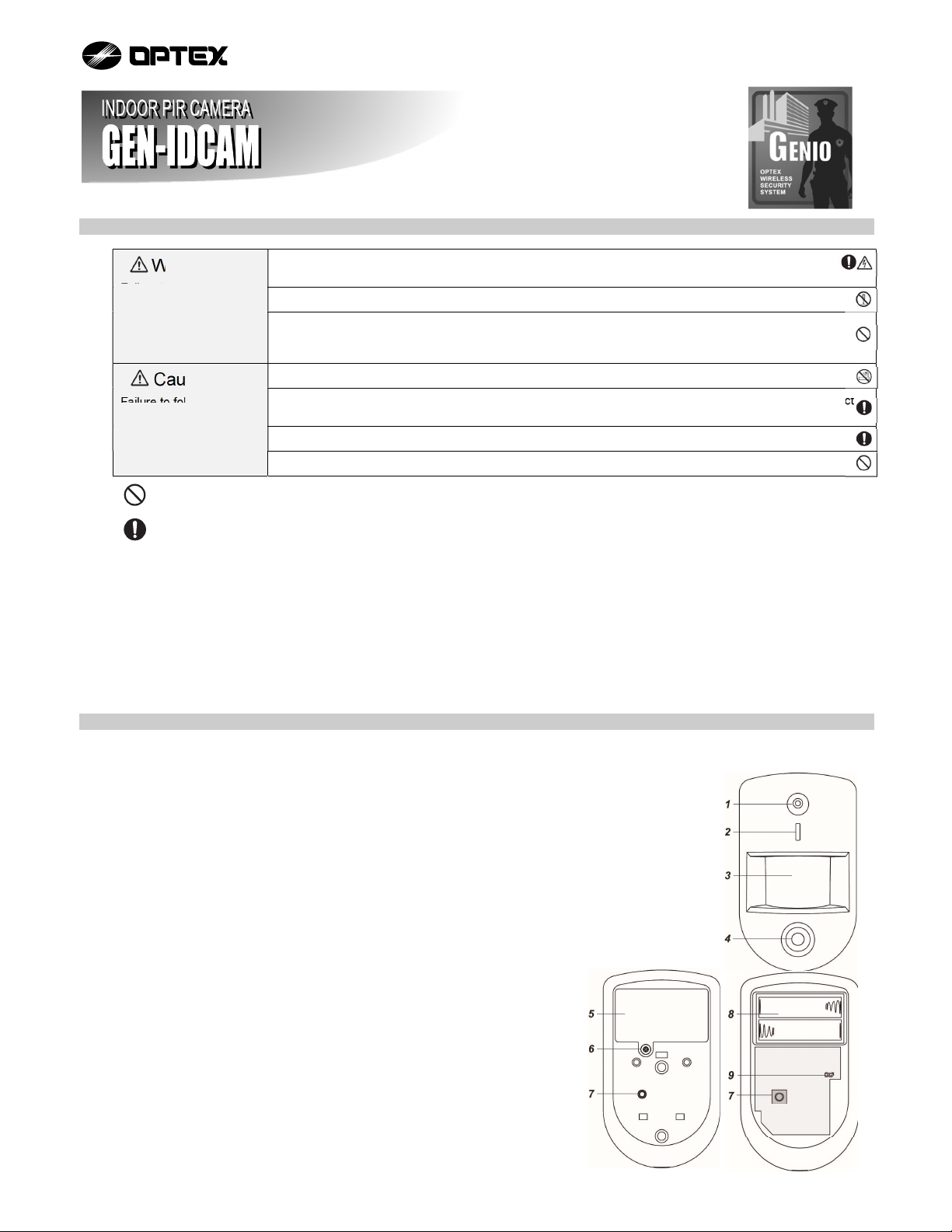
Step1. Remove the Battery Compartment Cover by loosening the Battery Compartment Screw.
Step2. Insert the batteries. Orient the battery according to the polarity indication.
Step3. Make sure the tamper switch is open.
Step4. Within 3 minutes after power on, Press and hold the function button for 10 seconds, release the button when both the Blue LED and
flash LED flash once. Please make sure to enable the permit-join feature on the router or coordinator of your ZigBee network.
Step5. After joining the ZigBee network, the PIR Camera will be registered in the security system in the network automatically. Please check the
ZigBee network coordinator, system control panel, or CIE (Control and Indicating Equipment) to confirm if joining and registration is
successful.
Step6. After joining the ZigBee network, if the PIR Camera loses connection with the ZigBee network, the LED will flash 20 minutes to indicate.
Please check your ZigBee network condition and PIR Camera signal range to correct the situation.
Jumper On
The jumper link is inserted
connecting the two pins.
Jumper Off
if the jumper link is removed
or “parked” on one pin.

REMOVING DEVICE FROM ZigBee NETWORK (FACTORY RESET)
To remove the PIR Camera from current ZigBee network, the PIR Camera must be put to Factory Reset to complete device removal. Factory Reset
function will clear the PIR Camera of its stored setting and information and prompt the PIR Camera to search for new ZigBee network.
Before removing device, make sure the PIR Camera is within current ZigBee network signal range
Step1. Delete the PIR Camera from current control panel / CIE.
Step2. The PIR Camera can only be reset within 3 minutes after power up. If the PIR Camera has been powered up for more than 3 minutes,
remove and reinsert the battery.
Step3. Make sure the tamper switch is open (released), press and hold the function button for 10 seconds, then release the button to reset
PIR Camera.
Step4. Upon reset, the PIR Camera will clear current ZigBee network setting and transmit signal to ZigBee coordinator to remove itself from
current ZigBee network. It will then actively search for available ZigBee network again and join the network automatically.
5 INSTALLATION
INSTALLATION GUIDELINE
The PIR Camera is designed to be mounted on either a flat surface or in a corner situation with fixing
screws and plugs provided.
The base has knockouts, where the plastic is thinner, for mounting purpose. Two knockouts are for
surface fixing and a triangular mounting bracket is used for corner fixing.
It is recommended to install the PIR Camera in the following locations.
Mount where the animals cannot come to the detection area by climbing on furniture or other objects.
Don’t aim the detector at stairways the animals can climb on.
In a position such that an intruder would normally move across the PIR’s field of view.
Between 1.9 and 2 m above ground for best performance. When mounted at 1.9 m above ground, it
gives a typical PET IMMUNE range of 7 m. As the PIR Pet-Immune Camera is higher from above ground, it gives a farther PET IMMUNE
range.
In a corner to give the widest view.
Where its field of view will not be obstructed e.g. by curtains, ornaments etc.
For a small 3 to 5 m room, install between 1.9 to 2 m above ground.
Limitations
Do not position a PIR Camera to look directly at a door protected by a Door Contact, this could cause the Door Contact and PIR Camera radio
signals to be transmitted at the same instant when entering, canceling each other out.
Do not install the PIR Camera completely exposed to direct sunlight.
Avoid installing the PIR Camera in areas where devices may cause rapid change of temperature in the detection area, i.e. air conditioner,
heaters, etc.
Avoid large obstacles in the detection area.
Not pointing directly at sources of heat e.g. Fires or boilers, and not above radiators.
Avoid moving objects in the detection area i.e. curtain, wall hanging etc.
USING PIR CAMERA WITH ZigBee ROUTER
NOTE>>
If PIR Camera installation location is away from your system control panel and requires ZigBee routers to improve signal strength. DO NOT
use a ZigBee Router without backup battery. A ZigBee router without battery will be powered down during AC power failure and the PIR
Camera connected to the router will lose connection with ZigBee network. Plan your PIR Camera installation location using only ZigBee router
with backup battery.
MOUNTING THE PIR CAMERA
Surface mounting
Step1. Remove the cover by loosening the Cover Screw using a Philips screwdriver.
Step2. Break through the 2 Surface knockouts at the center of base.
Step3. Use the holes as template to drill holes on the surface.
Step4. Insert the wall plugs if fixing it into plaster or brick.
Step5. Screw the base into the wall plugs.
Step6. Fit the cover onto the base and tighten the Cover Screw using a Philips screwdriver.
Corner mounting
Step1. Break through the two knockouts on the triangular bracket.
Step2. Use the two holes as template to drill holes on the corner surface.
Step3. Insert the wall plugs.
Step4. Screw the triangular bracket into the wall plugs with the two pointing sticks on top facing you.
Step5. Fit the PIR Camera onto the hooks of the triangular bracket.
6 APPENDIX (FOR DEVELOPERS ONLY)
PIR CAMERA CLUSTER ID
Device ID: _852_DEVICEID: 0x404 (proprietary)
Endpoint: 0x01
Server Side Client Side
Mandatory
Basic (0x0000) None
IAS Zone(0x0500)
Optional
_852_Cluster(0x0503) (proprietary) None

ATTRIBUTE OF BASIC CLUSTER INFORMATION
Identifier Name Type Range Access Default Mandatory /
Optional
0x0000 ZCLVersion Unsigned 8-
bit integer
0x00 –0xff Read
only
0x01 M
0x0001 ApplicationVersion Unsigned 8-
bit integer
0x00 –0xff Read
only
0x00 O
0x0003 HWVersion Unsigned 8-
bit integer
0x00 –0xff Read
only
0 O
0x0004 ManufacturerName Character
String 0 – 32 bytes Read
only Climax Technology O
0x0005 ModelIdentifier Character
string
0 – 32 bytes Read
only
(Model Version) O
0x0006 DateCode Character
String 0 – 16 bytes Read
only
O
0x0007 PowerSource 8-bit 0x00 –0xff Read
only
M
0x0010 LocationDescription Character
String
0 – 32 bytes Read /
Write
O
0x0011 PhysicalEnvironment 8-bit 0x00 –0xff Read /
Write
0x00 O
0x0012 DeviceEnabled Boolean 0x00 –0x01 Read /
Write 0x01 M
ATTRIBUTE OF IAS ZONE CLUSTER INFORMATION
Identifier Name Type Range Access Default Mandatory /
Optional
0x0001 ZoneState 8-bit
Enumeration
All Read
only
0x00 M
0x0002 ZoneType 8-bit
Enumeration All Read
only M
0x0003 ZoneStatus 16-bit bitmap All Read
only
0x00 M
0x0010 IAS_CIE_ADDRESS IEEE
ADDRESS
Valid 64bit IEEE
address
Read /
Write
M
0x0011 ZONE_ID Unsigned 8-bit
integer
All Read
only
0xFF M
7 SPECIFICATIONS
Model GEN-IDCAM
Detection method Passive infrared
PIR Camera
Coverage
7.0 m 90° wide
Frequency 2.4 GHz
Power source L91 Lithium battery: 2 units
Battery life Approx. 2.5 years (1 activations per day, 25°C)
Operating conditions -10°C to +50°C (up to 85% non-condensing)
Mounting height 1.9 m
Weight 180 g (not including battery)
8 DIMENSIONS
70
49
118
Unit: mm
Unit: mm
Other Optex Digital Camera manuals