59-3063-1 2212-27
EN
INS-QXI-ST
INS-QXI-ST
INSTALLATION INSTRUCTIONS
1
2
3
4
5
- Manufacture's statement
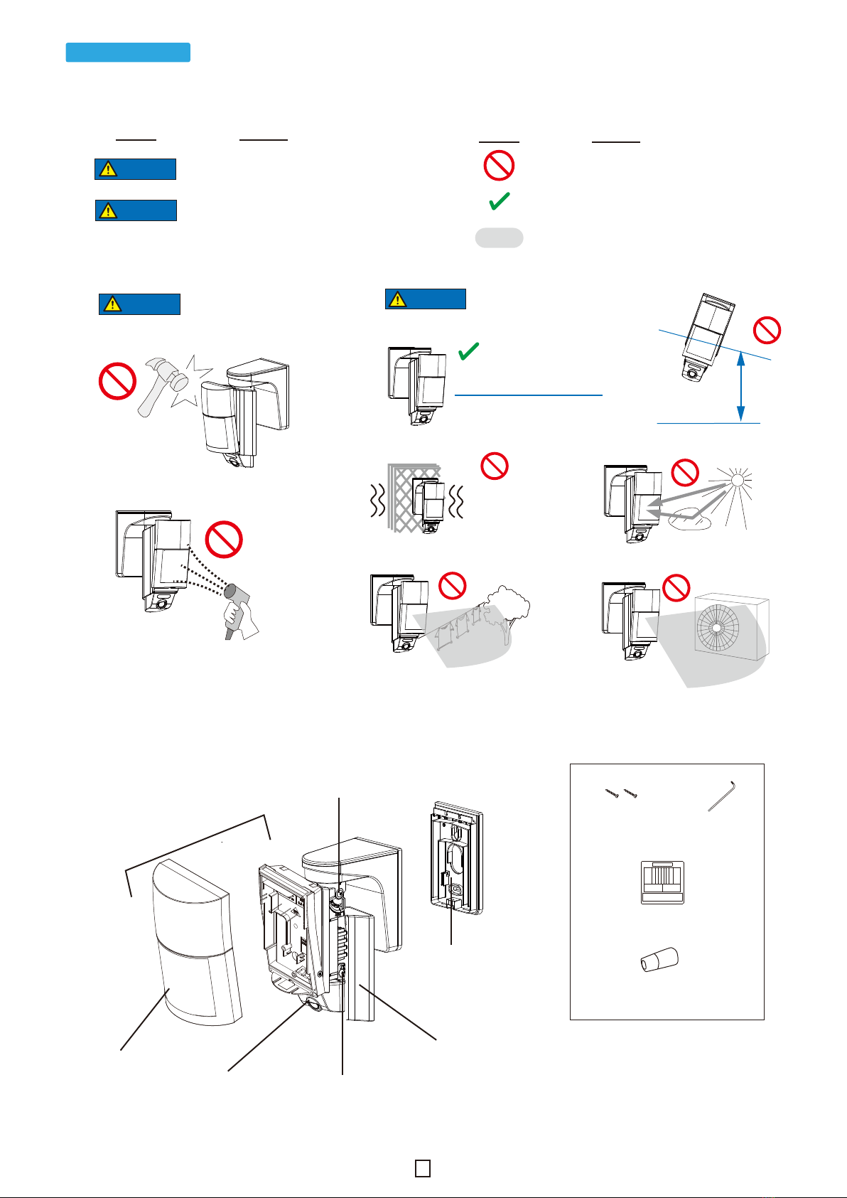
- Parts identification
- Accessories
- Specifications
- Dimensions
- Detection area
- LED indicator
- Compliance
- How to reset to the factory default
Before installation
Others
<< Contents >>
Page
2
3
5
6
11
12
Step
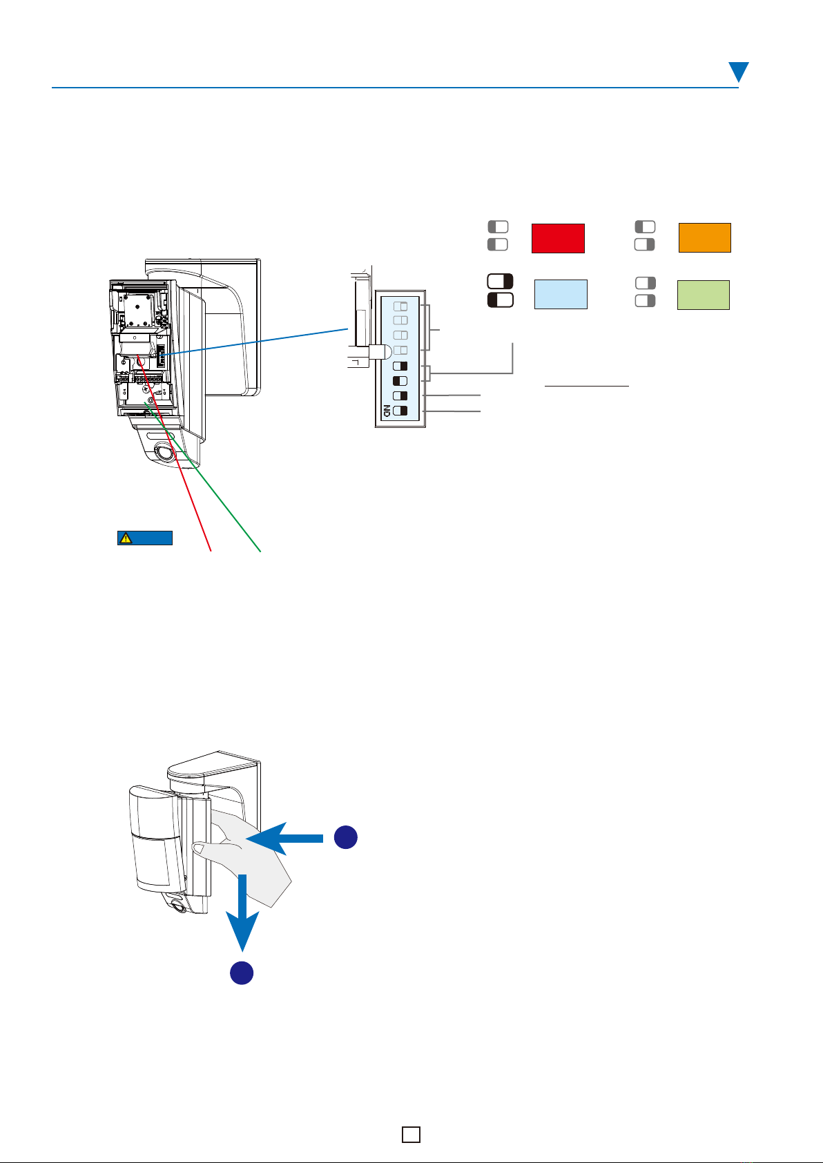
Enabled
Disabled
Installation
IP address settings
Device registration to CHeKT portal
DHCP
Camera angle and PIR area settings
Checking
VISUAL VERIFICATION PIR CAMERA
series
1
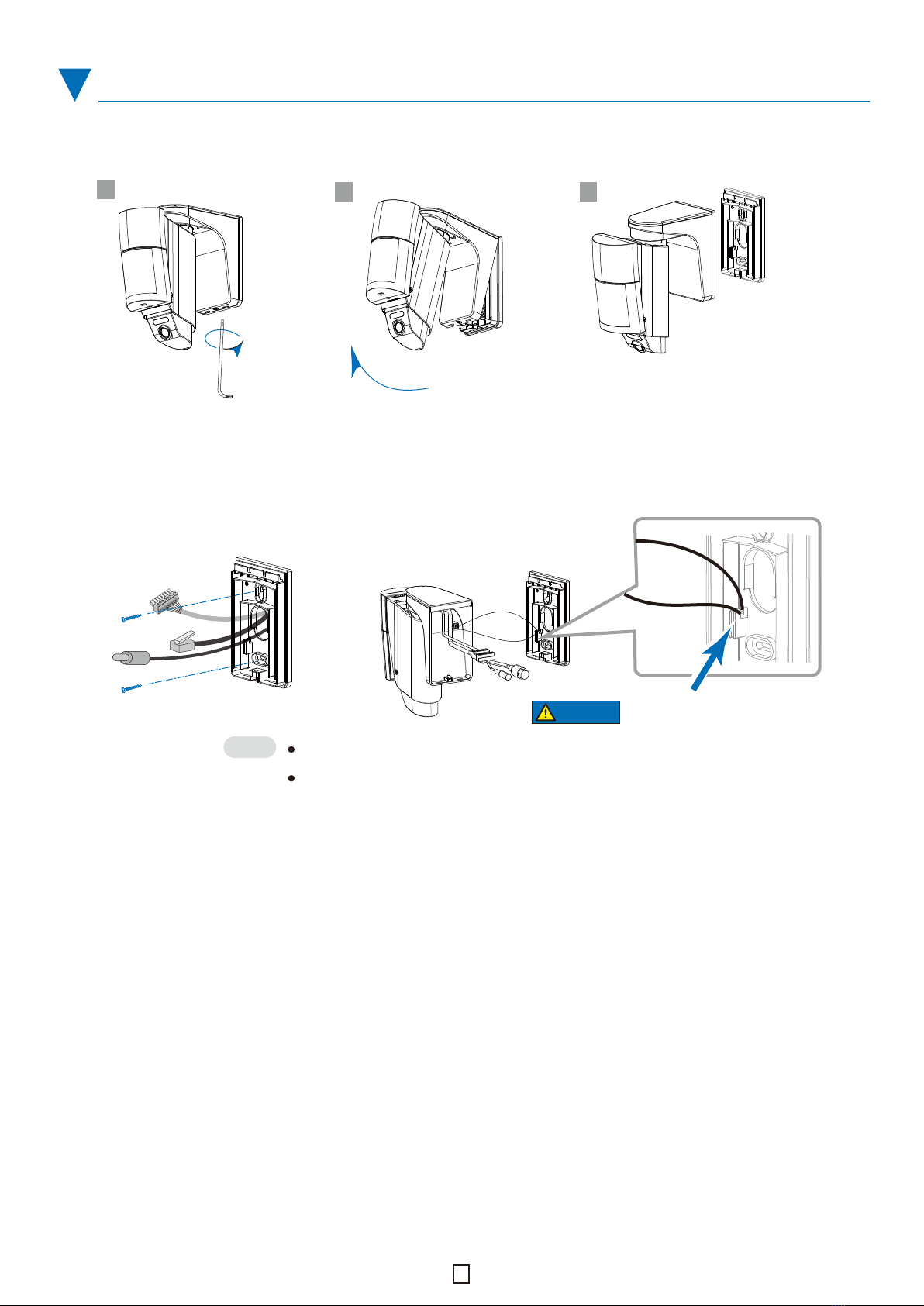
1-1. Remove the mounting plate
1-2. Install the mounting plate using 2 screws
1-3. Connect cables to the device
1-4. Secure the main body
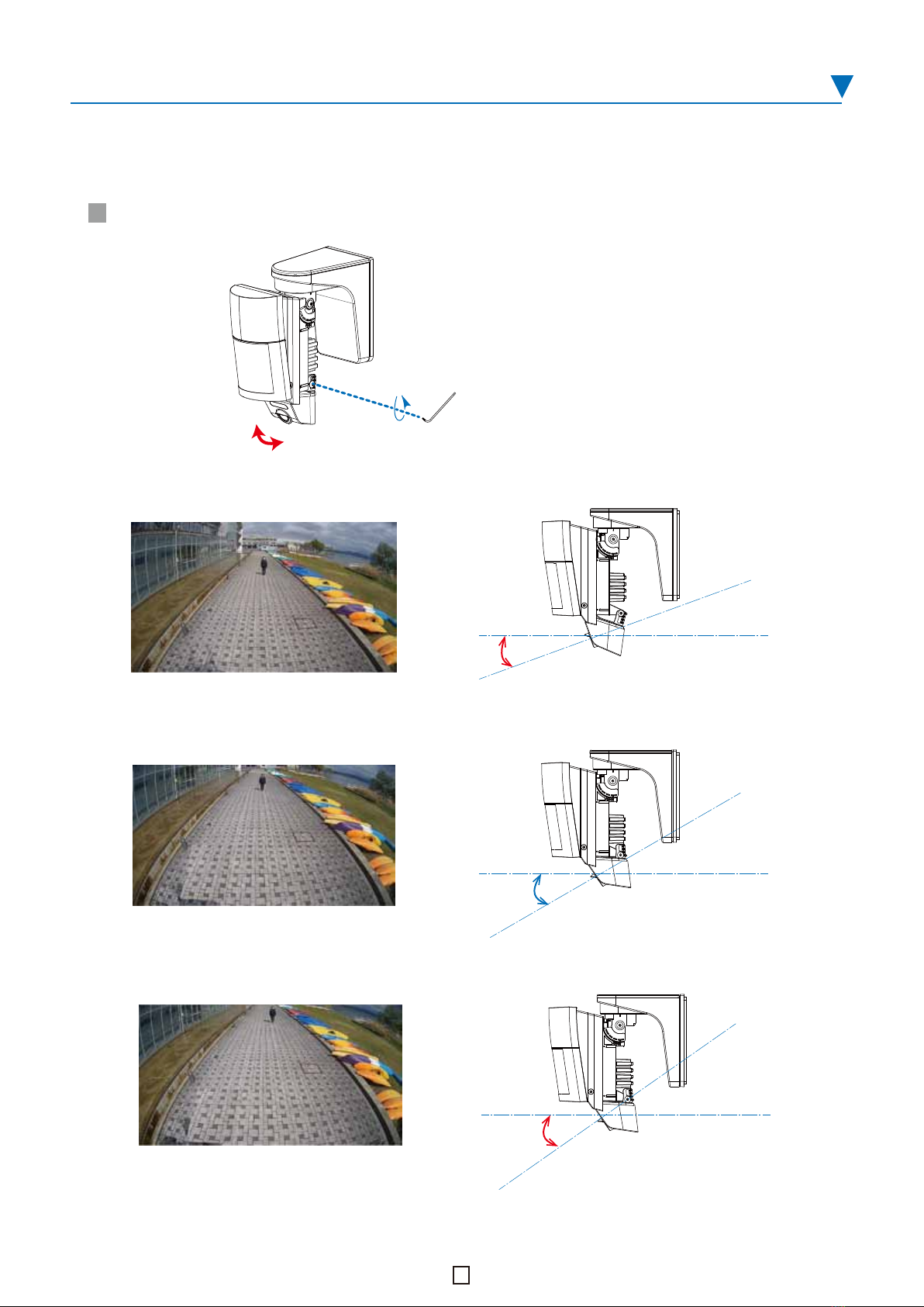
4-1. Horizontal adjustment
4-2. Vertical adjustment
4-3. PIR/VCA settings
4-4. PIR area masking
4-5. Switch settings
4-6. Put on the back cover
InSIght Camera manual
CHeKT support
Refer to the InSight Camera manual for details on
IP address settings.
InSIght Camera manual
https://navi.optex.net/manual/50426/en/?type=cameramanual
If you do not have a CHeKT account, request a dealer account
by visiting the CHeCK dealer site, before Step 3.
CHeKT dealer
www.chekt.com/registration
Refer to the CHeCK support site for more details.
CHeKT support
https://support.chekt.com
5-1. Walk test
5-2. System check