Optibelt ZRP User manual

TECHNICAL MANUAL
OPTIBELT POLYURETHANE
TIMING BELT DRIVES
optibelt
ZRM: AT5 und AT10
optiflex:
Sortiment
Inklusive:

1
Technical Manual
for
Polyurethane Timing Belt Drives
Optibelt ZRM/ZRP/ZRL timing belts are made from
polyurethane and are especially suitable for use in
difficult environmental conditions
Endless Optibelt ZRM/ZRP timing belts, with corre-
sponding Optibelt ZRS pulleys, provide non-slip,
synchronous transmission of power up to several
hundred kilowatts.
Where the requirement is for precise positioning in
linear drives and smoothly operating conveyor
systems, the open-ended and the joined endless
Optibelt ZRL timing belts provide the answer.
All essential information and the methods for calculat-
ing drives using Optibelt polyurethane timing belts are
contained in this manual. Should you have any further
questions, the free service provided by our application
engineers is readily available.

2
Produktionsstätten und Vertriebsorganisation der Arntz Optibelt Gruppe
Manufacturing and Distribution Organisation of the Arntz Optibelt Group
Produktionsstätten Factories
Arntz Optibelt GmbH
Postfach 10 01 32 · D-37669 Höxter/Germany
Corveyer Allee 15 · D-37671 Höxter/Germany
Tel. +49 (0) 52 71-6 21
Fax +49 (0) 52 71-97 62 00
A & M Belting Company Ltd.
Ballyraine Industrial Estate
Letterkenny Co. Donegal
Ireland
Tel. +353 (0) 74 91-2 50 66
Fax +353 (0) 74 91-2 50 61
Optibelt Produktions GmbH & Co. KG
Carl-Vollrath-Straße 4
D-07422 Bad Blankenburg
Tel. +49 (0) 3 67 41-48 30
Fax +49 (0) 3 67 41-4 21 01
Arntz Belting Company Ltd.
Pennyburn Pass
Londonderry BT48 0AE
Northern Ireland
Tel. +44-28 71-26 12 21
Fax +44-28 71-26 33 86
Transac S.A.
54, Rue de la Gare
F-68520 Burnhaupt-le-Haut/France
Tél. +33-3-89 62 75 20
Fax +33-3-89 62 75 29
Vertriebsorganisation Deutschland Distribution Organisation Germany
Optibelt GmbH
Corveyer Allee 15
37671 Höxter
Tel. +49 (0) 52 71-6 21
Fax +49 (0) 52 71-97 62 00
www.optibelt.com
Optibelt GmbH
Verkaufsbüro Nord
North Sales District
Corveyer Allee 15
D-37671 Höxter
Tel. +49 (0) 52 71-6 23 03
Fax +49 (0) 52 71-97 62 00
Optibelt GmbH
Verkaufsbüro Süd
South Sales District
Pfauhauser Straße 43
D-73240 Wendlingen
Tel. +49 (0) 70 24-71 00
Fax +49 (0) 70 24-5 27 92
Vertriebsorganisation Europa Distribution Organisation Europe
Finnland Finland
Optibelt Finland Oy
PL 58
Lampputie 4
FIN-00751 Helsinki
Puh. +358-9-3 46 14 00
Faksi +358-9-3 46 15 00
Großbritannien
United Kingdom
Optibelt (UK) Ltd.
5 Bishops Court
Winwick Quay
GB-Warrington WA2 8QY
Cheshire
Tel. +44-19 25-41 33 11
Fax +44-19 25-57 37 51
Frankreich France
Optibelt France S.A.S
54, Rue de la Gare
B.P. N°13
F-68520 Burnhaupt-le-Haut
Tél. +33-3-89 62 75 10
Fax +33-3-89 62 75 19
Polen Poland
Optibelt Polska Sp. z o.o.
ul. Budowlanych 11
PL-41-303 Da˛browa Górnicza
Tel. +48-32-260 1175/76
Faks+48-32-260 4208
Schweden Sweden
Optibelt Skandinaviska AB
Stadiongatan 60
S-21762 Malmö
Tel. +46-40-59 21 20
Direct +46-40-59 21 27
Fax +46-40-49 90 10
Niederlande Netherlands
Optibelt Nederland B.V.
Postbus 39
NL-2140 AA Vijfhuizen
Schipholweg 955
NL-2143 CE Boesingheliede
Tel. +31-23-5 55 16 51
Fax +31-23-5 55 19 26
Schweiz Switzerland
Optibelt AG
Bodenackerstrasse 70
CH-4657 Dulliken
Tel. +41-62-285 50 00
Fax +41-62-285 50 01
Ost-Europa
Eastern Europe GUS
Optibelt Russland
Varshavskoje Shosse,
125D, Korpus 1
113587 Moskau
Tel./Fax +7 09 59 95 05 41
Mobile +7 90 37 74 35 34
Dänemark Denmark
Optibelt Danmark A/S
International House
Center Boulevard
DK-2300 København S
Tlf. +45-32-47 32 34
Fax +46-40-49 90 10
Belgien Belgium
Optibelt GmbH
Filiaal België
Cornelis Schutstraat 28
B-2100 Deurne
Tél. +32-3-3 25 22 75
Fax +32-3-3 26 09 55
Spanien Spain
Optibelt España, S.A.
Apartado 1141
Rois de Corella, 12
E-08205 Sabadell
Tel. +34-93-7 20 79 60
Fax +34-93-7 11 64 90
Südost-Europa
South Eastern Europe
Optibelt GmbH
Südost-Europa · Office Wien
Carlbergergasse 38
A-1230 Wien
Tel. +43-1-8 65 31 00 19
Fax +43-1-8 65 31 00 27
Österreich Austria
Optibelt Österreich GmbH
Carlbergergasse 38
A-1230 Wien
Tel. +43-1-8 65 43 97
Fax +43-1-8 65 43 96
Italien Italy
Optibelt AG
Via Dandolo, 1
I-20025 Legnano (Mi)
Tel. +39-0331-48 10 20
Fax +39-0331-48 10 75
Vertriebsorganisation Nord- u. Südamerika Distribution Organisation North & South America
USA USA
Optibelt Corporation
1120 W. National Avenue
Addison, Illinois 60 101/USA
Tel. +1-630-628-84 00
Fax +1-630-628-61 75
Kanada Canada
Optibelt (Canada) Inc.
351 Steelcase Road West, Unit 8 & 9
L3R 4H9 Markham, Ontario/Canada
Tel. +1-905-477-8114
Fax +1-905-477-0857
Brasilien Brasil
Optibelt do Brasil Ltda.
Rua Henrique Monteiro Nr. 90
10 Andar-Pinheiros
CEP 05423-020 São Paulo-SP/Brasil
Vertriebsorganisation Asien Distribution Organisation Asia
Singapur Singapore
Optibelt Asia Pacific Pte. Ltd.
No. 4 Loyang Way 1, # 01-02/03
Singapore 508708
Tel. +65-6545 4682
Fax +65-6545 4685
China China
Optibelt Power Transmission (Shanghai) Co., Ltd.
# 55 Miaosan Road, Songjiang District
Shanghai 201612/P.R. China
Tel. +86-21-5768 7465
Fax +86-21-5768 7462
2

3
Contents
Foreword . . . . . . . . . . . . . . . . . . . . . . . . . . . . . . . . . . . . . . . . . . . . . . . . . . . . . . . . . . . . . 1
Manufacturing and Distribution Organisation of the Arntz Optibelt Group . . . . . . . . . . . . . . . . 2
Contents . . . . . . . . . . . . . . . . . . . . . . . . . . . . . . . . . . . . . . . . . . . . . . . . . . . . . . . . . . . . . 3
1 Product Description
1.1 Construction . . . . . . . . . . . . . . . . . . . . . . . . . . . . . . . . . . . . . . . . . . . . . . . . . . . . . . . 4
1.2 Applications . . . . . . . . . . . . . . . . . . . . . . . . . . . . . . . . . . . . . . . . . . . . . . . . . . . . . . . 6
1.3 Types and sections . . . . . . . . . . . . . . . . . . . . . . . . . . . . . . . . . . . . . . . . . . . . . . . . . . . 8
1.4 Special constructions . . . . . . . . . . . . . . . . . . . . . . . . . . . . . . . . . . . . . . . . . . . . . . . . . 9
2 Basics of Drive Design
2.1 Service factors, additional factors and formulae . . . . . . . . . . . . . . . . . . . . . . . . . . . . . . . 12
2.2 Symbols used in formulae . . . . . . . . . . . . . . . . . . . . . . . . . . . . . . . . . . . . . . . . . . . . . . 14
3 ZRM/ZRP Timing Belts
3.1 ZRM/ZRP resistance to chemicals . . . . . . . . . . . . . . . . . . . . . . . . . . . . . . . . . . . . . . . . 15
3.2 ZRM/ZRP optiflex timing belt range . . . . . . . . . . . . . . . . . . . . . . . . . . . . . . . . . . . . . . . 16
3.3 ZRM/ZRP belt selection graphs . . . . . . . . . . . . . . . . . . . . . . . . . . . . . . . . . . . . . . . . . . 24
3.4 ZRM/ZRP drive design . . . . . . . . . . . . . . . . . . . . . . . . . . . . . . . . . . . . . . . . . . . . . . . . 26
3.5 ZRM/ZRP tensioning . . . . . . . . . . . . . . . . . . . . . . . . . . . . . . . . . . . . . . . . . . . . . . . . . 28
3.6 ZRM/ZRP power rating table . . . . . . . . . . . . . . . . . . . . . . . . . . . . . . . . . . . . . . . . . . . . 29
4 Open-Ended and Joined Endless Optibelt ZRL Timing Belts for Linear Drives
and Conveying
4.1 ZRL timing belt range . . . . . . . . . . . . . . . . . . . . . . . . . . . . . . . . . . . . . . . . . . . . . . . . . 30
4.2 ZRL graph of torque . . . . . . . . . . . . . . . . . . . . . . . . . . . . . . . . . . . . . . . . . . . . . . . . . . 32
4.3 ZRL-M drive design . . . . . . . . . . . . . . . . . . . . . . . . . . . . . . . . . . . . . . . . . . . . . . . . . . . 34
4.4 ZRL-V drive design . . . . . . . . . . . . . . . . . . . . . . . . . . . . . . . . . . . . . . . . . . . . . . . . . . . 37
4.5 ZRL tensioning . . . . . . . . . . . . . . . . . . . . . . . . . . . . . . . . . . . . . . . . . . . . . . . . . . . . . . 40
4.6 ZRL circumferential force and torque table . . . . . . . . . . . . . . . . . . . . . . . . . . . . . . . . . . . 41
4.7 ZRL resistance to chemicals . . . . . . . . . . . . . . . . . . . . . . . . . . . . . . . . . . . . . . . . . . . . . 42
5 Design Hints, Dimensions and Tolerances
5.1 Allowances, length tolerances . . . . . . . . . . . . . . . . . . . . . . . . . . . . . . . . . . . . . . . . . . . 43
5.2 Standard pulleys, flanged pulleys, idlers, clamping plates and minimum numbers of teeth . . 44
5.3 Operating, safety and maintenance hints, installation . . . . . . . . . . . . . . . . . . . . . . . . . . . 46
5.4 Standards, pulley tolerances . . . . . . . . . . . . . . . . . . . . . . . . . . . . . . . . . . . . . . . . . . . . 48
5.5 Length measurement, width tolerances . . . . . . . . . . . . . . . . . . . . . . . . . . . . . . . . . . . . . 50
5.6 Problems, causes, remedies . . . . . . . . . . . . . . . . . . . . . . . . . . . . . . . . . . . . . . . . . . . . . 52
Taper Bushes, Timing Belt Pulleys and Clamping Plates
Taper bushes . . . . . . . . . . . . . . . . . . . . . . . . . . . . . . . . . . . . . . . . . . . . . . . . . . . . . . . 54
Timing belt pulleys . . . . . . . . . . . . . . . . . . . . . . . . . . . . . . . . . . . . . . . . . . . . . . . . . . . 55
Recommended pulleys – special constructions . . . . . . . . . . . . . . . . . . . . . . . . . . . . . . . . 90
Clamping Plates . . . . . . . . . . . . . . . . . . . . . . . . . . . . . . . . . . . . . . . . . . . . . . . . . . . . . 91
ZRM/ZRP Data Sheet and Notes . . . . . . . . . . . . . . . . . . . . . . . . . . . . . . . . . . . . . . . . . . . . 93
ZRL Data Sheet and Notes . . . . . . . . . . . . . . . . . . . . . . . . . . . . . . . . . . . . . . . . . . . . . . . . . 95

4
Introduction
Since the introduction of the first timing belt at the end of the 40’s,
this type of drive element has gained in importance for the
synchronous transmission of torque and power. The non-slip timing
belt has been successfully employed in many standard drives and
has provided economical design solutions in every sector of
mechanical engineering.
The position that the timing belt occupies today is due to the
development of tooth profiles and belt design. The Optibelt ZRM/
ZRP/ZRL single and double-section polyurethane timing belts are a
result of this progress. The properties specific to the polyurethane,
offer the following advantages:
●High resistance to abrasion
●Good to very good resistance to oil, grease and a
number of aggressive chemicals
●Colour fast
●Simple to weld, for attaching cleats and joining
endless to make belts of any length
●High resistance to tooth shear
●Good thermal tolerance (–30 °C to +80 °C)
●Good electrical insulation properties using poly-
urethane with Aramid tension cord
●Ageing resistant
●Ozone and UV resistant
Apart from the higher noise level at high belt speeds when
compared to V-belt drives, the timing belt has all of the advantages
of other drive mechanisms.
●Synchronous speed transmission, high angle and
positional accuracy due to the low-stretch tension
member and to the positive pulley/belt interlock.
●Double section belts permit multi-pulley arrange-
ments and contra-rotating pulleys.
●Belt flexibility allows high drive ratios requiring
minimum space.
●Low belt specific mass enables high belt speeds.
●Low-stretch tension cord means zero maintenance.
●High drive efficiency due to belt flexibility and lack
of slip.
●The low drive tension allows the use of smaller drive
bearings.
●No drive lubricant necessary, thus the drive is envi-
ronmentally friendly.
●Durable belt components ensure longer belt life.
1 Product Description
1.1 Construction
In addition to the features of the standard synchronised drive, the
Optibelt ZRM/ZRP/ZRL timing belts offer the additional advan-
tages of polyurethane, as shown above, as a contribution to the
economical solution of design problems.
Top surface
Tension cord
Tooth
Base
Construction: Timing belts
Fig.1.1: Timing belts
a) Top surface
The top surface of the belt is polyurethane. Its function is to hold and
support the tension cord. This abrasion-proof, thin and extremely
flexible layer also protects the tension cord against wear and the
effects of ambient conditions.
b) Tension cord
The tension cord of the endless Optibelt ZRM/ZRP timing belt is
spirally wound steel cord. The teeth, base and top surface form a
unit so that the tension cord is enclosed in polyurethane.
The extremely strong, low stretch tension cord has a very small
cross section.
The open-ended Optibelt ZRL-M belting has parallel steel or
Aramid tension cords. This is also the case with the joined endless
Optibelt ZRL-V timing belt.
c) Teeth and base
The polyurethane teeth transfer power between the pulley teeth and
the belt tension cord, whilst the polyurethane base cushions the
tension cord against the abrasion from the top of the pulley teeth
(see Fig. 1.3).
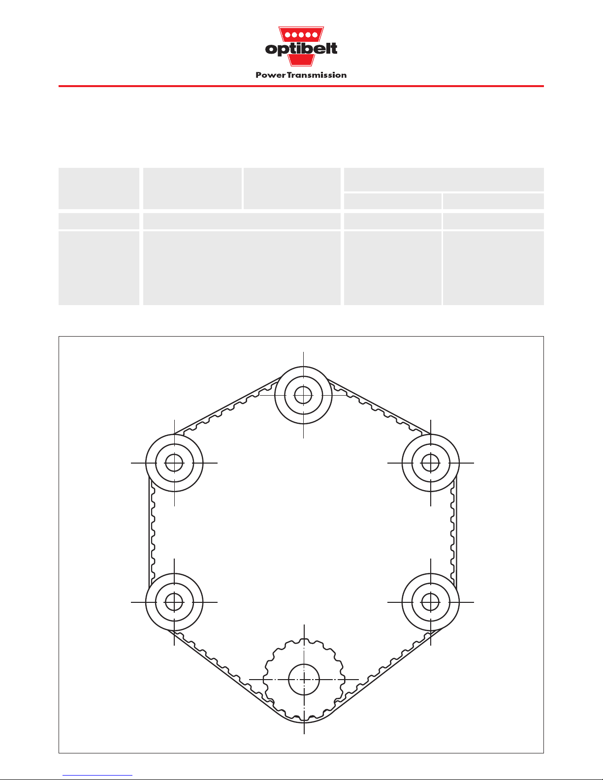
The durable, shear resistant belt teeth are so formed and arranged
as to engage with the matching pulley with minimum friction and
maximum precision. When six teeth on the belt type ZRL-V, and
twelve teeth or more on the ZRM, ZRP and ZRL-M belts are in mesh
with the small pulley at any one time, their shear resistance exceeds
the maximum permitted circumferential force of the timing belt.

5
1 Product Description
1.1 Construction
Fig.1.3: Timing belt / pulley relationship
Fig.1.2: Double section timing belt
Section
Overall
belt
thickness
h
s1
(mm)
Tooth
angle
2 β
(°)
Tooth
depth
h
t
(mm)
Tooth
width
at top
b
(mm
)
Tooth
pitch
t
(mm)
Overall
belt
thickness
h
s
(mm
)
Tooth
width
at base
s
(mm)
Table 1.1: Section dimensions, sections see Fig. 1.5, page 8,
Standards see Table 5.6, page 48
MXL 2.032 1.14 — 0.51 1.14 — 40
XL 5.080 2.30 — 1.27 2.57 — 50
L 9.525 3.60 — 1.91 4.65 — 40
H 12.700 4.30 — 2.29 6.12 — 40
XH 22.225 11.20 — 6.35 12.57 — 40
T2.5 2.500 1.30 — 0.70 1.50 — 40
T5 5.000 2.20 — 1.20 2.65 — 40
T5D 5.000 — 3.4 1.20 2.65 — 40
T10 10.000 4.50 — 2.50 5.30 — 40
T10D 10.000 — 7.0 2.50 5.30 — 40
T20 20.000 8.00 — 5.00 10.15 — 40
T20D 20.000 — 13.0 5.00 10.15 — 40
AT5 5.000 2.70 — 1.20 — 2.50 50
AT10 10.000 5.00 — 2.50 — 5.00 50
AT20 20.000 9.00 — 5.00 — 10.00 50
5M 5.000 3.60 — 2.10 — — —
8M 8.000 5.60 — 3.38 — — —
14M 14.000 10.00 — 6.10 — — —
The tooth pitch ‘t’ is the distance between two corresponding points
on adjacent teeth on either the belt or the pulley effective diameter.
When the timing belt is laid flat the tooth pitch ‘t’ can be measured
from tooth centre to centre.
When the belt is bent around a pulley the tooth pitch ‘t’ is measured
at the level of the tension cord, also called the effective radius. The
effective diameter ‘dd’ thus describes a circle which lies outside the
perimeter of the pulley (dd> da).
Construction of the double section timing belt
The construction of the double section timing belt is similar to the
normal timing belt already described. The number and spacing of
the teeth are identical on both sides of the belt, but the two sides
are offset to each other (see Fig. 1.2).
The tension cord and its position relative to the base and teeth are
the same. The maximum permitted power of the double section
timing belt is therefore not doubled but is the same as for the
corresponding normal belt. The power can be transmitted by both
sides of the belt as required.
Base
Tooth
Tooth
Base
Tension cord
da
dw

6
1 Product Description
1.2 Applications
Table 1.2: Types and applications
Type ZRM ZRP ZRL
ZRL-M ZRL-V
Applications Synchronous power transmission Linear drives Conveying
Examples: Machine tools Doors and door drives Conveyor systems
Textile machines Washing systems Ram conveyors
Printing presses Reciprocating drives Feeding systems
Packaging machines Mechanical handling Haul-off belts
Domestic appliances equipment Drives with large
Office machines Robots centre distances
Medical equipment Positioning drives
Fig. 1.4.1: Synchronous power transmission
Multi-spindle drives
• •
•
•
• •
•
•
• •
•
•
• •
•
•
• •
•
•

7
1 Product Description
1.2 Applications
Fig. 1.4.2: Linear drives
Fig. 1.4.3: Conveying
Inclined conveyors with cleats
Trolley drives
Positioning drives
•
•
•
•
•
•
•
•
••• •
•
•
•
•
••• •
•
•
•
•
•
•
•••••••
•
•
•
•
•
•
•
•
•
•
•
•••
•
•
•
•••
•
•
•
•
•• ••
•
•
•
•

8
1 Product Description
1.3 Types and sections
Type ZRM ZRP ZRL
ZRL-M ZRL-V
Construction manufactured endless open-ended joined endless
metric inch metric and inch
Section T2.5 MXL* T5 AT5 XL T5 AT5 XL
T5 T5D AT5* XL 5M* L L
T10 T10D AT10* L T10 AT10 8M* H T10 AT10 H
T20* T20D* AT20* T20 AT20* 14M* XH T20 XH
5M 8M 14M
Verzahnung ??? single, double (D) single single
Standard tension cord
steel (St), MXL = Aramid (AR) steel (St), Aramid (AR)
Special tension cord Aramid (AR) —
Table 1.3: Types and sections
∗Non stock (8M and 14M with steel tension cord can be supplied from stock)
Sections AT5; AT10; AT20 Sections 5M; 8M; 14M
Fig. 1.5: Sections, section dimensions see Table 1.1, page 5
Sections MXL; XL; L; H; XH; T2.5; T5; T10; T20 Sections T5D; T10D; T20D
Measurement/
identification units
••
•
•
•••••
•
•
•
•
•
••• •• •
•
•
•
•
•
•
•
•
•
•
•••••••
•
•
•
•
•
•
•• • •
•
•
•

9
1 Product Description
1.4 Special constructions
Table 1.4: Additional top surfaces
Linatex, Natural 40 – 30 to patterned (to 1.2; 1.6; no furniture industry,
red rubber + 60 1.6 mm thick), 2.4; 3.2; haul-off and
smooth (from 4.8; 6.4; conveying systems
2.4 mm thick), 8.0;
very good coef- 10.0;
ficient of friction, 12.7
abrasion resistant
Supergrip, PVC 40 – 30 to coarse structure, 4.5 conditionally woodworking
blue-green + 80 good coefficient industry,
of friction, inclined transport
abrasion resistant
under certain
conditions
HV 1-film, Poly- 85 – 30 to smooth, 1.0; yes food industry,
HV 2-film, urethane + 80 very good 2.0 glass transport
transparent abrasion
resistance,
superior wear
resistance
Foam PUR 40 – 30 to fine grain, 1.0; 2.0; yes packaging industry
Vulkolan, foam + 80 good coefficient 3.0; 4.0; (lightweight goods),
beige of friction, 5.0; 6.0 transport of
good abrasion sharp-edged objects
resistance,
cut resistant
Solid Poly- 70 – 30 to fine grain, 2.0; 3.0; yes packaging industry
Vulkolan, urethane + 80 good coefficient 5.0; 6.0 (heavy goods),
beige of friction, transport of
good abrasion sharp-edged objects
resistance,
superior wear
resistance
Porol, Cellular 25 – 30 to fine grain, 2.0; 3.0; yes transport of
black rubber + 90 very good coef- 5.0; 8.0; impact-sensitive
ficient of friction, 10,0 goods,
abrasion resistant suction systems
under certain (lightweight materials)
conditions,
cut resistant
PU 06, Poly- 50 – 30 to very fine grain, 2.0; 3.0; yes glass industry,
yellow or grey urethane + 80 high density, 4.0; 5.0; packaging industry,
good coefficient 8.0 transport of
of friction, sharp-edged objects
good abrasion
resistance,
cut resistant
Studs, PVC 65 – 30 to coarse structure, 1.5 yes food industry,
white + 80 good coefficient woodworking industry
of friction,
abrasion resistant
under certain
conditions
Intermediate thicknesses can be made by doubling or grinding the top surface cover.
Top surfaces other than the examples given in Table 1.4 are also available.
noitangiseD ruolocdnaruolocdnaruolocdnaruolocdnaruolocdna lairetaM ssendraH
.xorppa.xorppa.xorppa.xorppa.xorppa )AerohS()AerohS()AerohS()AerohS()AerohS(
erutarepmeT ecnatsiserecnatsiserecnatsiserecnatsiserecnatsiser
)C°(.ac)C°(.ac)C°(.ac)C°(.ac)C°(.ac seitreporP dradnatS sessenkcihtsessenkcihtsessenkcihtsessenkcihtsessenkciht
)mm()mm()mm()mm()mm(
dnaliO foorp-esaergfoorp-esaergfoorp-esaergfoorp-esaergfoorp-esaerg noitacilppalacipyT

10
Fabric facing
Optibelt timing belts can be supplied with polyamide fabric on
either the top face or the toothed face of the belt. This fabric offers
less friction resistance than polyurethane and is ideally suited for
facing on belts (PAR) used on ram conveyor applications. Fabric
covering on the toothed face (PAZ) is used to reduce static and
sliding friction on belts which need to be supported on this face by
plastic or metal rails. Support rails are used primarily on belt haul-
off and feeder sections where support idlers are widely spaced.
Fig. 1.6: Timing belt with fabric facing on both sides
1 Product Description
1.4 Special constructions
Optibelt timing belts can be adapted to the most varied of
applications in the conveying, control and handling fields, by the
appropriate choice of top surfaces, fabric facings and cleats.
The Optibelt ZRM/ZRP timing belts, intended for use for power
transmission can also be provided with an additional top surface.
Table 1.5: Special constructions
The special constructions shown in Table 1.5 can be combined with
one another.
Special ZRM ZRP ZRL
construction ZRL-M ZRL-V
Fabric facings
– top face (PAR) ●●
– toothed face (PAZ) ●●
Additional top surfaces ●●●●
Conveyor cleats ●●
* polyamide fabric is required where sliding friction is important
Which of the coefficients of friction is used depends upon whether
the conveyed components are static or sliding on the belt. The
coefficients of friction apply for dry conditions and can vary with
belt speed, heat dissipation rate and texture of the surface of the
materials in contact. The upper and lower limits of the coefficients
of sliding friction are based on a belt speed of 0.1 to 1.0 m/sec.
≥0.40 ≥0.25
≤0.70 ≤0.45
≥0.50 ≥0.20
≤0.90 ≤0.30
≥0.30 ≥0.20
≤0.50 ≤0.35
≥0.85* ≥0.30
≤1.00* ≤0.50
≥0.50 ≥0.20
≤0.85 ≤0.35
µ0µµ
0µ
R
z
= 16 µm
Rz= 6,3 µm
Table 1.6: Coefficients of friction
slairetamtcatnoC noitcirffostneiciffeoC
enahteruyloP gnicafcirbafRAP/ZAPtuohtiw enahteruyloP gnicafcirbafRAP/ZAPhtiw
noitcirfcitatsnoitcirfgnidilsnoitcirfcitatsnoitcirfgnidils
,leetS 5554
,muinimulA 0553
enelyhteyloP 5252
,ssalG
htooms 0503
,dooW
niargehthtiw 5353.0

11
Additional top surfaces
The top surface materials listed in Table 1.4 on page 9 improve
conveying rates by increasing the coefficient of friction. They also
protect the top surface of the belt. They allow the belt to be used
on a small incline or on a haul-off arrangement in which the belt is
used to overcome level differences. Where stringent demands are
made on the uniformity of the surface or thickness, the top surface
can also be ground.
Fig.1.7: Additional top surfaces e.g. studs, white
Conveyor cleats
The belts in the Optibelt programme can be fitted with conveyor
cleats. Like the timing belt, they are made of polyurethane and are
welded to the back of the belt.
By making positive contact with the transported goods, the con-
veyor cleats extend the range of applications for ZRL timing belting
as follows:
●uniform feed e.g. for production and assembly lines
●conveying of bulky items using belts running in
parallel
●inclined and vertical conveying to bridge differences
in levels
●positioning and switching in handling and control
systems
1 Product Description
1.4 Special constructions
The shapes and sizes of the cleats are adapted to the function they
are required to carry out. They can, for example, be provided with
holes if fixtures are to be attached e.g. for vertical conveying.
Cleats with V-shaped grooves on their upper faces are suitable for
conveying in longitudinal and transverse directions.
Fig.1.8: Cleats with unwelded back supports for large loads and
with holes for fixtures
Cleats should be narrow in the area of the weld and are usually
arranged opposite a belt tooth. The original flexibility of the timing
belt is thus retained. In order to achieve this, the required cleat
spacing ammust coincide with the tooth pitch t, and the belt length
Lwmust be matched to the number nmof cleats required for the
length of the conveyor in question. With particularly long timing
belts, the length tolerance of the belt must be taken into considera-
tion (see Table 5.2, page 43).
Lw= am· nmam= t · x x total number of teeth

12
dnasnoitidnocecivreS srevomemirpfoselpmaxesrevomemirpfoselpmaxesrevomemirpfoselpmaxesrevomemirpfoselpmaxesrevomemirpfoselpmaxe
h61otpuh61revoh61otpuh61revo
3.14.14.15.1
6.17.18.19.1
8.19.10.21.2
0.21.22.23.2
Total service factor c2
The total service factor comprises the basic service factor c0and
two further correction factors c6and c8.
Basic service factor c0
The basic service factor c0takes into account the daily duration of
operation, the type of prime mover and the type of driven machine.
As it is virtually impossible to cover every combination of prime
mover/machine/operating condition in a single standardised
summary, the basic service factors must be taken as guides only.
The final drive will depend upon the loads involved in each case.
Table 2.1: Basic service factor c
0
Type of service and examples of
machine applications
Service factor c0at number of operating hours per day
Very heavy duty drives, continuous
operation with high shock loading
Grinding mills
Calenders
Extruders
Piston pumps and compressors
Lifting gear
Heavy duty drives, intermittent
operation with medium to high
shock loading
Machine tools
Woodworking machines
Eccentric drives
Belt conveyor systems (heavy goods)
Medium drives, intermittent operation
with low to medium shock loading
Mixing machines
Kitchen machines
Printing machines
Textile machines
Packaging machines
Belt conveyor systems (heavy goods)
Lightweight drives, shock-free and
steady running
Measuring equipment
Film cameras
Office machinery
Belt conveyor systems (lightweight goods)
2 Basics of Drive Design
2.1 Service factors, additional factors and formulae
c0
Intermittent operation
Hydraulic motors
Low-speed turbines
Piston engines with small
number of cylinders
Steady operation
Electric motors
High-speed turbines
Piston engines with large
number of cylinders
c2= c0+ c6+ c8

13
Correction factors c6and c8
Like the basic service factor c0, the factors to be added for pulleys
and idlers c6and for start/stop frequency under load c8are to be
taken as approximations only. These factors are allowances to
be made for unusual operating conditions and are added where
applicable to the basic service factor c0.
Table 2.2: Correction factors c6and c8for special operating
conditions
Type of operating Designation and Remarks
conditions value of
correction factor
Use of c6= 0.2 0.2 per idler
tensioning and to a maximum of
guide idlers 1.0
Start/stop c8= 0.1 ... 0.3 depending upon
and/or frequency, up to
reversing approx. 1.5 times
under load nominal torque
with low start-up
torque (e.g. star/
delta connection)
c8= 0.3 ... 0.5 depending upon
frequency, above
approx. 1.5 times
nominal torque
with high start-up
torque
The correction factor c6applies when more than two pulleys are
used. Such use of additional pulleys must be separately checked at
the design stage.
Large drive torque of inertia should be classified as external loads.
2 Basics of Drive Design
2.1 Service factors, additional factors and formulae
Length factor c3for ZRM/ZRP belts
The approximate values for the length factor c3are given in
Table 2.3 and apply only to rotating highly loaded drives fitted
with ZRM/ZRP timing belts.
The length factor c3takes into account the increase or decrease of
belt flexing when using a short or long belt.
Note the units used for the individual parts of the formulae. The formulae for the driven torque and driven power also apply for the driver
side using the formula symbols MAn, PAn, dw1 and n1in place of MAb, PAb, dw2 and n2eff.
General
For i = 1 or z = z1= z2
Formulae for explanation of symbols see page 14
veff ==
i
eff === i=
d
w1 =d
w2 = (mm)
MAb = (Nm) PAb = (kW)
MAb · n2eff
9550
Sn3 · dw2 · n2eff
19100 · 1000
Sn3 · veff
1000
Generaldriven torque and driven power
dw2 · Sn3
2000
9550 · PAb
n2eff
dw2 · PAb
2 · veff
dw1 · n1
19100
z1· t
π
dw2 · n2eff
19100
z2· t
π
Drive calculation ZRM/ZRP see page 26
Drive calculation ZRL-M see page 34
Drive calculation ZRL-V see page 37
m
s
( )
Lw= 2 · anom + z · t (mm) anom = t (mm) zR=
zR– z
2
Lw
t
z2
z1
dw2
dw1
n1
n2eff
n1
n2
Table 2.3: Length factor c
3
for ZRM/ZRP belts
Section Pitch length LwLength factor
(mm) c3
MXL; T2.5 ≤190 0.8
> 190 ≤260 0.9
> 260 ≤400 1.0
> 400 1.1
XL; T5 (D); AT5 ≤440 0.8
> 440 ≤555 0.9
> 555 ≤800 1.0
> 800 1.1
L; T10 (D); AT10 ≤600 0.8
> 600 ≤920 0.9
> 920 ≤1500 1.0
> 1500 1.1
T20 (D); AT20 ≤1260 0.8
> 1260 ≤1880 0.9
> 1880 ≤3000 1.0
> 3000 1.1

14
2 Basics of Drive Design
2.2 Symbols used in formulae
Table 2.4 defines the essential parameters and relevant units used
in the formulae listed on page 13, and the drive design process.
Table 2.4: Symbols
Symbol Description Unit
a Required drive centre distance (mm)
anom Drive centre distance with standard belt length (mm)
bSt Standard belt width (mm)
bth Theoretical belt width (mm)
cvTension factor
c0Basic service factor
c2Total service factor
c2vorh Actual service factor
c3Length factor
c6Pulley and idler correction factor
c8Correction factor for start/stop and
reversing under load
daOutside diameter of pulley (mm)
DBOutside diameter of pulley over flanges (mm)
dwg Pitch diameter of the large pulley (mm)
dwk Pitch diameter of the small pulley (mm)
dw1 Pitch diameter of the driver pulley (mm)
dw1th Theoretical pitch diameter of the driver pulley (mm)
dw2 Pitch diameter of the driven pulley (mm)
evBelt deflection for checking belt tension (mm)
FvLoad used to set belt tension (N)
i Ratio required
ieff Ratio calculated from the number of pulley teeth
L Span length (mm)
Lwnom Pitch length of joined endless/open ended (mm)
timing belts (ZRL-V/ZRL-M)
LwSt Standard pitch length of endless (mm)
timing belts (ZRM/ZRP)
Lwth Theoretical pitch length of timing belts (mm)
MAb Torque (Nm)
MAbth Theoretical torque (Nm)
MAn Driver torque (Nm)
MBDesign torque including service factor (Nm)
MBth Theoretical design torque (Nm)
Mspez Transferrable torque per engaged tooth (Nm/cm)
and 10 mm belt width
nkSpeed of small pulley (min-1)
n1Speed of driver pulley (min-1)
n2Required speed of driven pulley (min-1)
n2eff Speed of driven pulley calculated from (min-1)
the number of teeth
PAn Driver power (kW)
PAb Driven power (kW)
PBDesign power including total service factor (kW)
Pspez Power per engaged tooth, 10 mm belt width (W/cm)
and 1 tooth of the small pulley
SaStatic shaft loading at correct tension (N)
SBn3 Design circumferential force including (N)
total service factor
Sn3 Circumferential force (N)
Sspez Transferrable circumferential force per (N)
engaged tooth and 10 mm belt width
Szul Transferrable circumferential force at (N)
maximum standard width
t Tooth spacing (mm)
v Required belt speed (m/s)
veff Actual speed (m/s)
x Allowance for centre distance adjustment (mm)
anom for belt tensioning
xvDeflection at correct tension (ZRL-M/ZRL-V) (mm)
y1/2/3 Allowance for centre distance adjustment (mm)
anom for belt installation, determined from
pulley arrangement
zeNumber of teeth in mesh with the small pulley –
for power transmission calculation
zemax Maximum number of teeth in mesh with the small
pulley – for power transmission calculation
zenom Number of teeth in mesh with the small pulley – actual
zkNumber of teeth on the small pulley
zRNumber of teeth on the timing belt
z1Number of teeth on the driver pulley
z2Number of teeth on the driven pulley
Symbol Description Unit
Fig.2.1: Drive arrangement
•
•
•
•
••• •
•
•
•
•
•
•
•
••
•
••
•
•
•
•
•
••
•

15
The data given on the chemical resistance of the Optibelt ZRM/ZRP
timing belts refers to the material polyurethane and is based on
laboratory figures arrived at under ideal conditions.
Classification of chemical resistance
1. No impairment of physical properties and working life
2. Minor impairment of physical properties and working life
3. Clearly visible swelling/disintegration, reduced physical
properties and shortened working life
4. Rapid disintegration
Copper sulphate, aqueous solution 20 1
Methanol 20 4
Methanol/petrol mixture 15 : 85 20 4
Methylene chloride 20 3
Methylethylketone 20 4
Mineral oil 80 3
n-Heptane 20 1
n-Hexane 50 1
Naphtha 20 2
Sodium carbonate,
saturated aqueous solution 20 2
Sodium chloride,
saturated aqueous solution 20 2
Sodium hydroxide, 1-N aqueous solution 20 2
Sodium phosphate, aqueous solution 20 1
Sodium soap, 20% aqueous solution 80 4
Sodium soap fat 20 3
Oleic acid 20 1
Palmitic acid 20 1
Phosphoric acid,
20-70% aqueous solution 20 1
Phosphoric acid, 85% aqueous solution 20 3
Mercury 20 1
SAE-10 oil 70 1
Nitric acid, 20% aqueous solution 20 4
Hydrochloric acid, 20% aqueous solution 20 2
Hydrochloric acid, 37% aqueous solution 20 4
Grease 20 2
Sulphuric acid, 20% aqueous solution 20 4
Sulphuric acid, 5% aqueous solution 20 2
Sulphurous acid 20 4
Seawater 20 2
Soap solution, aqueous 20 1
Soya oil 20 1
Stearic acid 20 1
Tannic acid, 10% aqueous solution 20 1
Turpentine 20 4
Carbon tetrachloride 20 4
Tetrahydrofuran 20 4
Toluol 20 4
Trichlorethane 20 4
Tricresyl phosphate 20 2
Water 100 4
Water 90 3
Water 20 1
Hydrogen 20 1
Plasticising oils 20 2
Xylol 20 4
3.1 ZRM/ZRP resistance to chemicals
Resistance of endless
optibelt
ZRM/ZRP timing belts
Table 3.1: ZRM/ZRP chemical resistance
Aluminium chloride,
5% aqueous solution 20 2
Formic acid 20 4
Ammonia 10% aqueous solution 20 2
Aniline 20 4
ASTM oil No. 1 80 3
ASTM oil No. 2 80 3
ASTM oil No. 3 80 3
Acetone 20 4
Petrol, “normal” 20 3
Petrol, “super” 20 3
Benzol 20 4
Borax solution 20 1
Boric acid, aqueous solution 20 1
Butane 20 1
Butanol 20 2
Butyl acetate 20 4
Calcium chlorate (I),
5% aqueous solution 20 4
Calcium chloride, aqueous solution 20 1
Calcium hydrogen sulphide,
aqueous solution 20 1
Chlorine, gaseous 20 4
Chromic acid
10 : 50% aqueous solution 20 4
Cyclohexane 20 2
Cyclohexanol 20 1
Diesel fuel 20 2
Dimethyl formamide 20 4
Ferric (III) chloride, 5% aqueous solution 40 3
Acetic acid, 20% aqueous solution 20 3
Ethanol 20 3
Ethyl acetate 20 4
Ethyl ether 20 3
Formaldehyde, 37% aqueous solution 20 3
Freon-11 20 2
Freon-113 20 1
Freon-12 54 1
Freon-22 20 3
Glycerine 20 1
Hydraulic fluid 20 2
Iso-octane 70 1
Iso-propanol 20 3
Potassium hydroxide,
1-N aqueous solution 20 3
Kerosene 20 2
Carbon dioxide 20 1
Copper chloride, aqueous solution 20 1
Medium Temperatur
(°C) Beständig-
keit Medium Temperatur
(°C) Beständig-
keit

16
–5.2TnoitceS mm5.2hctipmm5.2hctipmm5.2hctipmm5.2hctipmm5.2hctip mm5hctip–5TnoitceS mm01hctip–01TnoitceS
.oNtleB hctiP
)mm(
.oN
hteetfo.oNtleB
hctiP
)mm(
.oN
hteetfo.oNtleB
hctiP
)mm(
.oN
hteetfo.oNtleB
hctiP
)mm(
.oN
hteetfo
Standard widths bSt (mm):
4, 6, 8, 10, 12
Standard widths bSt (mm):
6, 8, 10, 12, 16, 20, 25
Standard widths bSt (mm):
10, 12, 16, 20, 25, 32, 50
3.2 ZRM/ZRP timing belt range
optibelt
ZRM timing belts, metric sizes
Further sizes on request. * Non stock
Section Pitch Tooth Overall Tooth Tooth
depth belt width angle
thickness
th
th
ss2β
(mm) (mm) (mm) (mm) (°)
T2.5 2.5 0.70 1.30 1.50 40
T5 5.0 1.20 2.20 2.65 40
T10 10.0 2.50 4.50 5.30 40
Construction: polyurethane with steel tension cord
Table 3.2: ZRM timing belt range
LwSt
T2.5/120 120.0 48
T2.5/160 160.0 64
T2.5/177.5 177.5 71
T2.5/200 200.0 80
T2.5/230 230.0 92
T2.5/245 245.0 98
T2.5/265 265.0 106
T2.5/285 285.0 114
T2.5/305 305.0 122
T2.5/317.5 317.5 127
T2.5/330 330.0 132
T2.5/380 380.0 152
T2.5/420 420.0 168
T2.5/480 480.0 192
T2.5/500 500.0 200
T2.5/540 540.0 216
T2.5/600 600.0 240
T2.5/650 650.0 260
T2.5/780 780.0 312
T2.5/915 915.0 366
T2.5/950 950.0 380
T5/165 165.0 33
T5/185 185.0 37
T5/200 200.0 40
T5/215 215.0 43
T5/220 220.0 44
T5/225 225.0 45
T5/245 245.0 49
T5/250 250.0 50
T5/255 255.0 51
T5/260 260.0 52
T5/270 270.0 54
T5/275 275.0 55
T5/280 280.0 56
T5/295 295.0 59
T5/300 300.0 60
T5/305 305.0 61
T5/325 325.0 65
T5/330 330.0 66
T5/340 340.0 68
T5/350 350.0 70
T5/355 355.0 71
T5/360*360.0 72
T5/365 365.0 73
T5/375 375.0 75
T5/390 390.0 78
T5/400 400.0 80
T5/410 410.0 82
T5/420 420.0 84
T5/425 425.0 85
T5/440*440.0 88
T5/445*445.0 89
T5/450 450.0 90
T5/455 455.0 91
T5/460*460.0 92
T5/475 475.0 95
T5/480 480.0 96
T5/500 500.0 100
T5/510 510.0 102
T5/525 525.0 105
T5/545 545.0 109
T5/ 550 550.0 110
T5/ 560 560.0 112
T5/ 575 575.0 115
T5/ 590*590.0 118
T5/ 600 600.0 120
T5/ 610 610.0 122
T5/ 620 620.0 124
T5/ 625*625.0 125
T5/ 630 630.0 126
T5/ 640 640.0 128
T5/ 650 650.0 130
T5/ 660 660.0 132
T5/ 675*675.0 135
T5/ 690 690.0 138
T5/ 700 700.0 140
T5/ 720 720.0 144
T5/ 725 725.0 145
T5/ 750 750.0 150
T5/ 780 780.0 156
T5/ 800*800.0 160
T5/ 815 815.0 163
T5/ 840 840.0 168
T5/ 850 850.0 170
T5/ 860*860.0 172
T5/ 900 900.0 180
T5/ 940 940.0 188
T5/ 990 990.0 198
T5/1000 1000.0 200
T5/1075 1075.0 215
T5/1100 1100.0 220
T5/1115*1115.0 223
T5/1140*1140.0 228
T5/1215 1215.0 243
T5/1350*1350.0 270
T5/1380 1380.0 276
T5/1440 1440.0 288
T10/ 260 260.0 26
T10/ 370 370.0 37
T10/ 400 400.0 40
T10/ 410 410.0 41
T10/ 440 440.0 44
T10/ 450 450.0 45
T10/ 500 500.0 50
T10/ 530 530.0 53
T10/ 550*550.0 55
T10/ 560 560.0 56
T10/ 600 600.0 60
T10/ 610 610.0 61
T10/ 630 630.0 63
T10/ 650 650.0 65
T10/ 660 660.0 66
T10/ 690 690.0 69
T10/ 700 700.0 70
T10/ 720 720.0 72
T10/ 750 750.0 75
T10/ 780 780.0 78
T10/ 800*800.0 80
T10/ 810 810.0 81
T10/ 840 840.0 84
T10/ 850*850.0 85
T10/ 880 880.0 88
T10/ 890 890.0 89
T10/ 900 900.0 90
T10/ 910 910.0 91
T10/ 920 920.0 92
T10/ 950 950.0 95
T10/ 960 960.0 96
T10/ 970 970.0 97
T10/ 980 980.0 98
T10/1000*1000.0 100
T10/1010 1010.0 101
T10/1050 1050.0 105
T10/1080 1080.0 108
T10/1100 1100.0 110
T10/1110 1110.0 111
T10/1140 1140.0 114
LwSt LwSt LwSt
zRzRzR
zR
Order example for ZRM: 10 T2.5/200
Width (mm)
Section
Pitch length (mm)
••
•
•
•••••
•
•
•

17
deunitnoc,01TnoitceSmm5hctip–D5TnoitceSmm01hctip–D01TnoitceS
.oNtleB
hctiP
)mm(
.oN
hteetfo.oNtleB
hctiP
)mm(
.oN
hteetfo.oNtleB
hctiP
)mm(
.oN
hteetfo
Standard widths bSt (mm):
10, 12, 16, 20, 25, 32, 50
Standard widths bSt (mm):
6, 8, 10, 12, 16, 20, 25
Standard widths bSt (mm):
10, 12, 16, 20, 25, 32, 50
Section Pitch Tooth Overall Tooth Tooth
depth belt width angle
thickness
th
th
s1 s2β
(mm) (mm) (mm) (mm) (°)
T5D 5.0 1.20 3.40 2.65 40
T10D 10.0 2.50 7.00 5.30 40
3.2 ZRM/ZRP timing belt range
optibelt
ZRM double section timing belts, metric sizes
Further sizes on request. * Non stock
Table 3.2 continued
LwSt zR
LwSt zRzR
LwSt
T10/1150 1150.0 115
T10/1200 1200.0 120
T10/1210 1210.0 121
T10/1240 1240.0 124
T10/1250 1250.0 125
T10/1300 1300.0 130
T10/1320 1320.0 132
T10/1350 1350.0 135
T10/1390 1390.0 139
T10/1400 1400.0 140
T10/1420 1420.0 142
T10/1440 1440.0 144
T10/1450 1450.0 145
T10/1460 1460.0 146
T10/1500 1500.0 150
T10/1560 1560.0 156
T10/1600 1600.0 160
T10/1610 1610.0 161
T10/1700 1700.0 170
T10/1750 1750.0 175
T10/1780 1780.0 178
T10/1800*1800.0 180
T10/1880 1880.0 188
T10/1960 1960.0 196
T10/2250 2250.0 225
T5/ 300 D*300.0 60
T5/ 350 D*350.0 70
T5/ 400 D*400.0 80
T5/ 410 D 410.0 82
T5/ 450 D*450.0 90
T5/ 460 D 460.0 92
T5/ 480 D 480.0 96
T5/ 500 D 500.0 100
T5/ 515 D 515.0 103
T5/ 550 D 550.0 110
T5/ 590 D 590.0 118
T5/ 600 D*600.0 120
T5/ 620 D 620.0 124
T5/ 650 D 650.0 130
T5/ 700 D 700.0 140
T5/ 750 D 750.0 150
T5/ 800 D 800.0 160
T5/ 815 D 815.0 163
T5/ 850 D*850.0 170
T5/ 860 D 860.0 172
T5/ 900 D 900.0 180
T5/ 940 D 940.0 188
T5/1100 D 1100.0 220
T10/ 260 D 260.0 26
T10/ 530 D 530.0 53
T10/ 600 D 600.0 60
T10/ 630 D 630.0 63
T10/ 660 D 660.0 66
T10/ 700 D 700.0 70
T10/ 720 D 720.0 72
T10/ 750 D 750.0 75
T10/ 800 D 800.0 80
T10/ 840 D 840.0 84
T10/ 900 D 900.0 90
T10/ 980 D 980.0 98
T10/1000 D*1000.0 100
T10/1100 D 1100.0 110
T10/1200 D*1200.0 120
T10/1210 D 1210.0 121
T10/1240 D 1240.0 124
T10/1250 D 1250.0 125
T10/1300 D*1300.0 130
T10/1320 D 1320.0 132
T10/1350 D 1350.0 135
T10/1400 D 1400.0 140
T10/1420 D 1420.0 142
T10/1500 D 1500.0 150
T10/1600 D*1600.0 160
T10/1610 D 1610.0 161
T10/1700 D 1700.0 170
T10/1800 D 1800.0 180
T10/1880 D 1880.0 188
Order example for ZRM D: 50 T 10/1420 D
Width (mm)
Section
Pitch length (mm)
Double section timing belts
T20 and AT sizes
on request
Construction:
polyurethane with steel tension cord
•
•
••• •• •
•
•
•
•
•
•
•

18
mm230.2hctip–*LXMnoitceS mm80.5hctip–LXnoitceS
.oNtleB .oN hteetfo.oNtleB .oN
hteetfo.oNtleB .oN
hteetfo
)hcni()mm()hcni()mm()hcni()mm(
Further sizes on request. * Non stock: minimum order 1 sleeve
3.2 ZRM/ZRP timing belt range
optibelt
ZRP timing belts, inch sizes
Section Pitch Tooth Overall Tooth Tooth
depth belt width angle
thickness
th
th
ss2β
(mm) (mm) (mm) (mm) (°)
MXL 2.032 0.51 1.14 1.14 40
XL 5.080 1.27 2.30 2.57 50
L9.525 1.91 3.60 4.65 40
Table 3.3: ZRP timing belt range
Construction: polyurethane with Aramid (MXL) or steel tension cord (XL, L)
K 240 MXL 2.40 60.96 30
K 280 MXL 2.80 71.12 35
K 320 MXL 3.20 81.28 40
K 360 MXL 3.60 91.44 45
K 400 MXL 4.00 101.60 50
K 440 MXL 4.40 111.76 55
K 480 MXL 4.80 121.92 60
K 520 MXL 5.20 132.08 65
K 560 MXL 5.60 142.24 70
K 600 MXL 6.00 152.40 75
K 640 MXL 6.40 162.56 80
K 680 MXL 6.80 172.72 85
K 720 MXL 7.20 182.88 90
K 760 MXL 7.60 193.04 95
K 800 MXL 8.00 203.20 100
K 840 MXL 8.40 213.36 105
K 880 MXL 8.80 223.52 110
K 920 MXL 9.20 233.68 115
K 960 MXL 9.60 243.84 120
K 1000 MXL 10.00 254.00 125
K 1040 MXL 10.40 264.16 130
K 1080 MXL 10.80 274.32 135
K 1120 MXL 11.20 284.48 140
K 1160 MXL 11.60 294.64 145
K 1200 MXL 12.00 304.80 150
K 1240 MXL 12.40 314.96 155
K 1280 MXL 12.80 325.12 160
K 1320 MXL 13.20 335.28 165
K 1360 MXL 13.60 345.44 170
K 1400 MXL 14.00 355.60 175
K 1440 MXL 14.40 365.76 180
K 1480 MXL 14.80 375.92 185
K 1520 MXL 15.20 386.08 190
K 1560 MXL 15.60 396.24 195
K 1600 MXL 16.00 406.40 200
K 1640 MXL 16.40 416.56 205
K 1680 MXL 16.80 426.72 210
K 1720 MXL 17.20 436.88 215
K 1760 MXL 17.60 447.04 220
K 1800 MXL 18.00 457.20 225
K 1840 MXL 18.40 467.36 230
K 1880 MXL 18.80 477.52 235
K 1920 MXL 19.20 487.68 240
K 1960 MXL 19.60 497.84 245
K 2000 MXL 20.00 508.00 250
K 2040 MXL 20.40 518.16 255
K 2080 MXL 20.80 528.32 260
K 2120 MXL 21.20 538.48 265
K 2160 MXL 21.60 548.64 270
K 2200 MXL 22.00 558.80 275
K 2240 MXL 22.40 568.96 280
K 2280 MXL 22.80 579.12 285
K 2320 MXL 23.20 589.28 290
K 2360 MXL 23.60 599.44 295
K 2400 MXL 24.00 609.60 300
K 2480 MXL 24.80 629.92 310
K 2560 MXL 25.60 650.24 320
K 2640 MXL 26.40 670.56 330
K 2720 MXL 27.20 690.88 340
K 2800 MXL 28.00 711.20 350
K 2880 MXL 28.80 731.52 360
K 2960 MXL 29.60 751.84 370
K 3040 MXL 30.40 772.16 380
K 3120 MXL 31.20 792.48 390
K 3200 MXL 32.00 812.80 400
zR
Pitch length
LwSt zR
Pitch length
LwSt zR
Pitch length
LwSt
K 60 XL*6.00 152.40 30
K 70 XL*7.00 177.80 35
K 76 XL*7.60 193.04 38
K 80 XL*8.00 203.20 40
K 84 XL*8.40 213.36 42
K 90 XL*9.00 228.60 45
K 94 XL*9.40 238.76 47
K 96 XL*9.60 243.84 48
K 100 XL 10.00 254.00 50
K 102 XL*10.20 259.08 51
K 104 XL*10.40 264.16 52
K 106 XL*10.60 269.24 53
K 110 XL 11.00 279.40 55
K 114 XL*11.40 289.56 57
K 116 XL*11.60 294.64 58
K 120 XL 12.00 304.80 60
K 124 XL*12.40 314.96 62
K 126 XL*12.60 320.04 63
K 128 XL*12.80 325.12 64
K 130 XL 13.00 330.20 65
K 136 XL*13.60 345.44 68
K 140 XL 14.00 355.60 70
K 150 XL 15.00 381.00 75
K 152 XL*15.20 386.08 76
K 154 XL*15.40 391.16 77
K 160 XL 16.00 406.40 80
K 166 XL*16.60 421.64 83
K 170 XL 17.00 431.80 85
K 180 XL 18.00 457.20 90
K 186 XL*18.60 472.44 93
K 190 XL 19.00 482.60 95
K 200 XL 20.00 508.00 100
K 210 XL 21.00 533.40 105
K 212 XL*21.20 538.48 106
K 220 XL 22.00 558.80 110
K 230 XL 23.00 584.20 115
K 240 XL 24.00 609.60 120
K 250 XL 25.00 635.00 125
K 254 XL*25.40 645.16 127
K 260 XL 26.00 660.40 130
Sleeve width: 127 ±10 mm
Order example for ZRP: K 120 XL 037
K = plastic
(polyurethane)
Pitch length code
Pitch length (inch x 10)
Section
Width code
Width (inch x 100)
Standard widths bSt:
1/8" = 3.175 mm 3/16" = 4.764 mm 1/4" = 6.35 mm 5/16" = 7.94 mm
Code No.:
012 019 025 031
Standard widths bSt, continued on page 19:
1/4" = 6.35 mm 5/16" = 7.94 mm
Code No.:
025 031
••
•
•
•••••
•
•
•

19
3.2 ZRM/ZRP Timing Belt Range
optibelt
ZRP timing belts, inch sizes
Section Pitch Tooth Overall Tooth Tooth
depth belt width angle
thickness
th
th
ss2β
(mm) (mm) (mm) (mm) (°)
MXL 2.032 0.51 1.14 1.14 40
XL 5.080 1.27 2.30 2.57 50
L9.525 1.91 3.60 4.65 40
Further sizes on request. * Non stock: minimum order 1 sleeve
Table 3.3, continued:
Construction: polyurethane with Aramid (MXL) or steel tension cord (XL, L)
K 270 XL 27.00 685.80 135
K 290 XL 29.00 736.60 145
K 300 XL 30.00 762.00 150
K 320 XL*32.00 812.80 160
K 330 XL 33.00 838.20 165
K 360 XL*36.00 914.40 180
K 376 XL*37.60 955.04 188
K 384 XL*38.40 975.36 192
K 390 XL 39.00 990.60 195
K 414 XL*41.40 1051.56 207
K 460 XL*46.00 1168.40 230
K 480 XL*48.00 1219.20 240
K 512 XL*51.20 1300.48 256
K 550 XL*55.00 1397.00 275
K 564 XL*56.40 1432.56 282
K 630 XL*63.00 1600.20 315
K 670 XL*67.00 1701.80 335
K 124 L 12.40 314.30 33
K 150 L 15.00 381.00 40
K 165 L*16.50 419.10 44
K 173 L*17.30 439.42 46
K 187 L 18.70 476.20 50
K 210 L 21.00 533.40 56
K 225 L 22.50 571.50 60
K 240 L 24.00 609.60 64
K 255 L 25.50 647.70 68
K 270 L 27.00 685.80 72
K 285 L 28.50 723.90 76
K 300 L 30.00 762.00 80
K 322 L 32.20 819.10 86
K 345 L 34.50 876.30 92
K 367 L 36.70 933.40 98
K 375 L*37.50 952.50 100
K 390 L 39.00 990.60 104
K 420 L 42.00 1066.80 112
K 427 L*42.70 1084.58 114
K 450 L 45.00 1143.00 120
K 480 L 48.00 1219.20 128
K 510 L 51.00 1295.40 136
K 525 L*52.50 1333.50 140
K 540 L 54.00 1371.60 144
K 600 L 60.00 1524.00 160
Pitch length
LwSt zR
Pitch length
LwSt zR
Sleeve width: 150 ±10 mmSleeve width: 150 ±10 mm
Order example for ZRP: K 480 L 150
K = plastic
(polyurethane)
Pitch length code
Pitch length (inch x 10)
Section
Width code
Width (inch x 100)
Standard widths bSt, continued for page 18:
3/8" = 9.53 mm 1/2" = 12.7 mm
Code No.:
037 050
Standard widths bSt:
1/2" = 12.7 mm 3/4" = 19.05 mm 1" = 25.4 mm 1 1/2" = 38.1 mm
Code No.:
050 075 100 150
••
•
•
•••••
•
•
•
deunitnoc,mm80.5hctip–LXnoitceS mm525.9hctip–LnoitceS
.oNtleB .oN
hteetfo.oNtleB .oN
hteetfo
)hcni()mm()hcni()mm(
This manual suits for next models
4
Table of contents