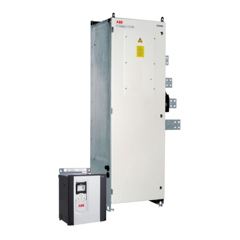
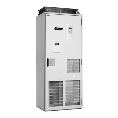
ABB ACS2000 DFE User manual

—
MEDIUM VOLTAGE DRIVES
ACS2000, 4 kV
User manual


TABLE OF CONTENT
004 – 012 General information on manual
and equipment
013 – 019 Safety
020– 037 Power electronics and cabinet
features
038– 052 Control system
053– 056 Transportation, storage and
disposal
057– 063 Mechanical installation
064– 073 Electrical installation
074 – 075 Commissioning
076– 084 Local operation
085– 095 CDP Control panel
096– 111 Troubleshooting and maintenance
—
Table of content

4ACS2000, 4 KV USER MANUAL
Copyright notice
The information in this manual is subject to change
without notice.
This manual and parts thereof must not be
reproduced or copied, or disclosed to third parties,
nor used for any unauthorized purpose without
written permission from ABB Inc., Medium
Voltage Drives.
The hardware described in this manual is provided
under a license and may be used, copied, or
disclosed only in accordance with the terms
of such license.
Document identification
• Ownership: ABB Inc.
• Document number: 2UEA001270
• Revision index: F
• Issue date: 04.01.2014
Equipment covered by the manual
This manual covers standard equipment and
provides generic information on the equipment.
The manual does not claim to cover all variations
and details of the equipment, nor to consider all
eventualities that may arise during installation,
commissioning, operation and maintenance of the
equipment.
If the equipment is adapted to specific customer
needs or applications, and handling, installation
and operation of the equipment are affected
by these modifications, information on these
modifications is provided in the appropriate
documentation (e.g. layout drawings, wiring
diagrams, technical data, engineering notes).
If information is required beyond the instructions
in this manual refer the matter to ABB. See section
Contact information.
—
General information on
manual and equipment
—
Frame Normal duty range kW [hp]
Drive type code

5
GENERAL INFORMATION ON MANUAL AND EQUIPMENT
Recommended maintenance service schedule
Manuals about fieldbus interfaces
Technical data sheets of the drive
Outline drawing(s) of the equipment
This parts manual is generated for each drive. Includes all information
necessary to identify a component
Provides detailed information on the MV (Medium Voltage) switchgear
Power cable specifications for drive connections
Pulse encoder specifications
Motor temperature supervision information
Descriptions of actual signals, control and status words, and control
parameters and their default settings
Information on the root cause of an alarm or fault and provides hints for
corrective measures
Provides instructions for remote monitoring
disconnect operation guide
Provides detailed information on the integral input contactor
disconnect option
Structure of the user documentation
The complete set of user documentation of a
standard drive consists of this manual and
supplementary documentation that is provided in
the following appendices, located on the CD:
—
Contact information
Address: ABB Inc.
Medium Voltage Drives
Email: mv[email protected]om
www.abb.us/drives
Global: www.abb.com

6ACS2000, 4 KV USER MANUAL
Target groups and required qualifications
The equipment presented in this manual is part of
an industrial environment where voltages are
present that contain a potential hazard of electric
reason, only personnel who have a thorough
environment and have obtained the required
qualification should handle, install, operate or
maintain the equipment.
The manual addresses personnel who are
installation, operation and maintenance of the
equipment. The personnel must carry out the
cause physical harm or danger and ensures
the safe and reliable function of the equipment.
Commissioning of drive equipment must
only be performed by qualified and certified ABB
personnel.
Handling
—
Chapter Handling Operation Maintenance
General information xxxx
Safety xxxx
Power electronics and cabinet features, Overview x x
Transportation x
Mechanical installation x x
Electrical installation x
Operation x
Troubleshooting and maintenance x
Mechanical installation
Personnel must be qualified to prepare the
installation site according to the site and
equipment requirements and to perform
the installation accordingly.
Electrical installation
relevant electrical codes and specifications
covering low and medium voltage equipment,
be experienced with electrical wiring principles
and understand the electrical symbols typically
used in wiring diagrams.
Operation
Personnel include all persons who operate
the equipment as required for the specified
process and be adequately trained to operate
converter technology is not required.
Maintenance
Personnel must be thoroughly familiar with the
construction of the equipment, be adequately
grounding procedures for the equipment.

7
GENERAL INFORMATION ON MANUAL AND EQUIPMENT
User’s responsibilities
It is the responsibility of those in charge of the
equipment to ensure that each person involved in
the installation, operation or maintenance of the
equipment has received the appropriate training
and has thoroughly read and clearly understands
the instructions in this manual and the relevant
safety instructions.
Those in charge of the equipment must ensure
that the equipment is used as specified in the
contractual documents, operated under
the conditions stipulated in the technical
specifications and on the rating plate of
the equipment, and serviced in the
intervals as specified by ABB.
Unauthorized modifications and constructional
changes of the equipment are not permitted.
Quality certificates and applicable standards
The following certificates and conformity
declarations are available with ABB:
• ISO 9001/ISO 14001 certificates stating
that ABB Inc. has implemented and maintains
a management system that fulfills the
requirements of the normative standards
• EC Conformity Declaration
• Standards and certifications
EN, IEC, CE and cUL.
Trademarks
companies and organizations are designated
as such. The absence or presence of such a
designation should, however, not be regarded
used in this manual:
Writing conventions
The following icons and text conventions are used
in the manual.
Corporation
Corporation
International (P.I.)
International, Ltd.
organization
DeviceNet Vendor Association, Inc.
Illustrates an illuminated pilot light
or pushbutton
pressed
Arrows indicate an alternating
display message
Refers to further information
in a separate document
• Bulleted list
Used to list items or steps in a
procedure, where the sequence
does not matter
Bulleted list of a
subsection
following a main
paragraph
Used to list items or for
procedures, where the sequence
does not matter
Steps of a procedure to be
followed in the specified order
—
Figure legend, numbers identify
the items referred to in the
illustration above
Bold
Used to highlight switches to be
operated, status messages shown
in a display and special terms
UPPERCASE Refer to a parameter
Italic
Used for references to illustrations,
chapters and supplementary
documentation

8ACS2000, 4 KV USER MANUAL
and location photos unless expressly stated. The
electrical layout, the physical order, and the
topology are shared between all frames.
• Terminal Entry Unit (TEU) and LV COntrol Unit
(COU) are shared with all frames, left bay
• The Input Filter Unit (IFU), filter bay, grows to
accommodate the higher current for each frame
• The INverter Unit (INU) and power modules,
right bay, grow to accommodate the higher
current for each frame
Meaning of terms and abbreviations
The following table lists terms and abbreviations
you should be familiar with when using the manual.
Some of the terms and abbreviations used in the
manual are unique to ABB and might differ from
the normal usage.
Term/Abbreviation Meaning
AFE
AMC circuit board
Application and Motor Controller. The digital signal processor is the heart of the control system of the
(INU) of the drive
CDP
Control/Display Panel. Removable controller of the drive located on the exterior of the terminal entry
unit door
Converter
COU
relays and the IOEC modules
DC Direct current
DDCS
Distributed drive control system. DDCS is an acronym for a fieldbus communication protocol designed
Drive
Drive system
The drive system includes all equipment used to convert electrical into mechanical power to give
motion to the machine
DriveBus
DriveDebug
specialist’s tool used to diagnose, tune and troubleshoot ABB drives
DriveMonitor™
DriveMonitor is a monitoring and diagnostics system that allows secure access to the drive via the
the user to read/display equipment status and improve equipment performance
EMC
Electromagnetic compatibility. All measures to suppress electromagnetic disturbances caused by
different electrical equipment in the same electromagnetic environment, and to strengthen the
immunity of the equipment to such disturbances
Equipment
Ground Earth

9
GENERAL INFORMATION ON MANUAL AND EQUIPMENT
The following documents are available for supplementary information:
Term/Abbreviation Meaning
To ground
The conducting path (e.g. conductor) between the electric equipment (e.g. frequency converter) and
the earth. The electric equipment is connected to the earth, e.g. by a grounding set
or a grounding switch
IFU
Input filter unit. The IFU is a tuned filter: inductors, resistors and capacitors that reduce harmonic
INT Interface
INU
Inverter unit of the drive. The INU converts the DC voltage to the required AC motor voltage
and frequency
IOEC module
Term of ABB’s I/O system. The I/O module is an active input or output device for digital
or analog signals
LED Light emitting diode
Line voltage RMS voltage of the main power supply of the drive – line to line
LV Low voltage
MCB MV switchgear
MV switchgear
device of the drive system and connects / disconnects the main power supply to the drive. The MV
switchgear must be controlled entirely by the drive
NP Neutral point
PCB Printed circuit board
PE Protective earth
Phase module
The phase module is a compact assembly of wired components including power semiconductors and
PPCS
Power plate communication system. PPCS is an acronym for a fieldbus communication protocol
designed for high speed data transfer via fiberoptic cables between the AMC circuit board and phase
INTerface circuit boards
RTD
Resistance temperature detector or device. The RTD is a temperature sensor where the change in
electrical resistance is used to measure the temperature
Safeline ABB synonym for uninterruptible power supply
TEU Short form for terminal entry unit of the drive
Zero speed threshold
Used in the manual to indicate that the drive has reached the value “zero speed” that is set in a
Title Document number Location
Appendix B
Appendix B
Appendix B
Anybus DeviceNet module – user manual
Anybus EtherNet IP module – user manual
Anybus ControlNet module – user manual
Spare parts list Appendix F
MV switchgear guide Appendix G
Power cable specification Appendix H
Motor temperature supervision Appendix L
Troubleshooting guide. The troubleshooting guide provides information on the
root cause of an alarm or fault and provides hints for corrective measures. Appendix N
Appendix O
Integral input contactor disconnect operation guide Appendix P
Induction motor specification
Service and maintenance manual
Preventive maintenance manual

10 ACS2000, 4 KV USER MANUAL
Delivery typically comprises the following items
—
01
Items covered by
1
2
3
57
8
4
6
Interior detail
Drive
Fan outlet box Installed on the drive
LV (low voltage)
Shipped zip tied to the grounding switch handle
Redundant fan (option) Installed on the drive when this option is selected
Rating label Drive identification
Document pouch
is located inside the control compartment
MV (medium voltage)
Shipped in the document pouch located inside the control compartment

11
GENERAL INFORMATION ON MANUAL AND EQUIPMENT
Delivery typically comprises the following items
—
02
Items covered by
1
2
3
57
8
49
6
Interior detail
Drive
Fan outlet box Installed on the drive
LV (low voltage)
Shipped zip tied to the grounding switch handle
Redundant fan (option) Installed on the drive when this option is selected
Rating label Drive identification
Document pouch
is located inside the control compartment
MV (medium voltage)
Shipped in the document pouch located inside the control compartment
Standard fan Installed on the drive

12 ACS2000, 4 KV USER MANUAL
Delivery typically comprises the following items
The drive and accessories are identified by the type
code printed on the rating label (see item 5 in
(control compartment) door.
Besides information on equipment identification,
the label provides important information on rated
voltage, frequency and current of the main and the
auxiliary power supply.
Tools
ABB offers various tool sets containing all
necessary tools and equipment for installation,
commissioning and maintenance of the drive.
—
Items covered by
1
2
3
57
8
4
9
6
Interior detail
Drive
Fan outlet box Installed on the drive
LV (low voltage)
Shipped zip tied to the grounding switch handle
Redundant fan (option) Installed on the drive when this option is selected
Rating label Drive identification
Document pouch
is located inside the control compartment
MV (medium voltage)
Shipped in the document pouch located inside the control compartment
Standard fan Installed on the drive
—
Frame Normal duty range kW [hp]
Drive type code

13
SAFETY
General safety information
To maintain safety and minimize hazards, observe
the following:
•
all foreign objects are removed from the drive
all internal and external covers are securely
or bolted
•
that:
the main and auxiliary power supply to the drive
discharged
safety ground connections are in place
appropriate personal protective equipment is
provided and used when required
everyone involved is informed
•
protective earmuffs
•
sure that:
the relevant safety codes and standards are
observed
all energy sources for the equipment are
turned off
barriers and appropriate covers are used on
equipment which is still live
everyone involved is informed
• In case of fire in the drive room:
Observe the established rules and regulations
for fire protection
Only firemen with appropriate protective
equipment are allowed to enter the drive room
Meaning of safety instructions
Safety instructions are used to highlight a potential
compliance can jeopardize the safety of personnel,
the equipment and the environment.
indicates a hazardous situation which, if
not avoided, will result in death or serious injury.
indicates a hazardous situation which, if
not avoided, could result in death or serious injury.
indicates a hazardous situation which, if
not avoided, could result in minor or moderate
injury.
is used to address practices not related to
personal injury.
The safety instructions are derived from the
following standards:
•
Graphical symbols – Safety colors and safety
signs – Part 2: Design principles for product
safety labels
•
American National Standard for Product Safety
Information in Product Manuals, Instructions, and
Other Collateral Materials
—
Safety
DANGER
WARNING
CAUTION
NOTICE
DANGER
WARNING
CAUTION
NOTICE
DANGER
WARNING
CAUTION
NOTICE
DANGER
WARNING
CAUTION
NOTICE

14 ACS2000, 4 KV USER MANUAL
Possible residual risks
integrator and / or the plant owner when
•
magnetic fields which can cause a hazard to
• Drive system components can move
unintentionally when being commissioned,
operated, or serviced due to, for example:
Operation of the equipment outside the scope
of the specifications
Incorrectly assembled or installed equipment
Incorrectly connected cables
External influence on, or damage to the
equipment
Software errors
Faulty hardware
• Hazardous voltages can be present on drive
system components caused by, for example:
Operation of the equipment outside the
scope of the specifications
External influence on, or damage to the
equipment
Induced voltages by external equipment
Condensation on equipment components,
or pollution
Faulty hardware
• High temperatures, noise, particles, or gases
can be emitted from drive system components
caused by, for example:
Operation of the equipment outside the
scope of the specifications
External influence on, or damage to the
equipment
Software errors
Faulty hardware
• Hazardous substances can be emitted from drive
system components due to, for example:
Incorrect disposal of components
Safety labels and signs
Safety labels
Safety labels are attached to the cabinet where
necessary to alert personnel of potential hazards
important to read and understand these labels.
The instructions on the safety labels must always
legible.
A label that is damaged or missing must be
replaced. Contact ABB for replacement.
Label identification
The safety labels are identified by means of a
number printed in the footer of the safety label.
The last two digits of the safety label number
identify the language of the label text. In Figure 04,
for example, the last two digits 09 identify English.
—
—
04
Safety label identification

15
SAFETY
Label location
Figures 05 and 06 indicate the placement of safety
labels on the drive.
—
05
Front of unit label
locations
1
2
3
5
4
Label number Label description
capacitors to discharge and ground equipment before opening door
is OFF. To ground equipment, the pilot light must be ON before rotating the
handle to grounded (O) position
Danger – This Equipment does not provide isolation. Separate isolating means
switchgear guide, located on the CD, for additional information

16 ACS2000, 4 KV USER MANUAL
—
06
unit label locations
—
07
Fire fighting sign
—
—
06
—
07
—
2
4
1
3
Label number Label description
Danger – Rotating fan blades! Fans may start automatically at any time.
removing the casing
Danger – Hazardous voltage inside. Disconnect power and ground equipment
before removing this cover
Caution – Burn hazard. Components may be very hot
* One label on each side of the drive.
Dimensions:
50 x 30 mm [2 x 1.2 in] Diameter: 32 cm [12.5 in]
Safety signs
Depending on the delivery, the following additional
safety signs may be provided:
Fire fighting
This sign explains the procedure for fighting fire in
electrical equipment. The sign should be installed
Heart pacemaker
The magnetic field of the drive can influence the
be installed at the entrance to the drive room or
the drive!

17
SAFETY
—
09
Potential equipment
hazard locations
4
Inside covers of Terminal Entry Unit (TEU)
Outside covers
Potential equipment hazards
are present inside the cabinet.
Potential equipment hazard locations
To maintain safety and minimize hazards, strictly
observe the following:
•
or remove an outside wall or a cover (4), as long as
the drive is energized
• Do not remove any of the covers (1) inside the
cabinet when the drive is energized
• Do not energize the equipment before all internal
covers (1) have been securely fastened
• Components inside the cabinet may be hot after
the drive has been in operation. Before opening a
cover or door, wait until the fan has stopped
•
on the drive
Safety measures
To maintain safety when the equipment is powered
Figure 10) is secured by two safety measures.
open unless these safety steps are completed.
The grounding switch must be moved to the
grounded position, which can only be done after
1
2
3
COU/TEU section Front view Rear view
information.
Frame 1
the AFE/INU door only after the main power has
been switched off and the ground switch is moved
to the grounded position.
Frame 2
the filter compartment door only after the main
power has been switched off and the ground
switch is moved to the grounded position. Once
this door has been opened, the AFE/INU door can
be opened by releasing the top and bottom draw
latches located inside the door.
Frame 3
the filter compartment door only after the main
power has been switched off and the ground
switch is moved to the grounded position. Once
this door has been opened, the left AFE/INU door
can be opened. After opening this door, the right
AFE/INU door can be opened by releasing the top
and bottom draw latches located inside the door.

18 ACS2000, 4 KV USER MANUAL
Light pressure needs to be applied to the bottom
of the door during the closing of each door in order
: Do not use excessive pressure to bottom
of door during closing. Excessive force may cause
damage to the drive.
the drive becomes operational. Once all doors
can be operated.
located on the CD, for detailed information.
located just inside the AFE/INU doors at the
between filter compartment door and converter
doors, requiring the doors to be closed in the
reverse order. The right AFE/INU door must be
closed and latched, followed by the left AFE/INU
door and, finally, the filter compartment door.
Hazardous voltage!
All doors must be closed and secured to prevent
unintentional contact with energized components.
•
before turning the drive on. Repair or replace the
• Use care when servicing the drive, being careful
Excessive pressure could cause the bar to bend
• Do not disable this safety feature
DANGER
WARNING
CAUTION
NOTICE
DANGER
WARNING
CAUTION
NOTICE
1
2
3
Grounding switch (grounded position)
AFE/INU compartment door
—
10
AFE/INU door
safety measures

19
SAFETY
2
3
Access doors
Rotating bar
—
11
door additional
safety measure
1

20 ACS2000, 4 KV USER MANUAL
—
Power electronics and cabinet features
The ACS2000 is an air-cooled, general purpose variable frequency drive
for the control of standard induction motors with 4 kV voltage.
Overview
electronic components, the drive produces nearly
sinusoidal current and voltage waveforms at its
input transformers and induction motors.
The following sections provide an overview of the
available auxiliary and main power configurations
and introduce the power electronic components of
the drive. The cooling system and cabinet features
such as the grounding switch and the door
Drive topology
Topology
This section describes the main design features
and introduces the major power electronic
components of a typical ACS2000 drive.
If you have ACS2000 with the integral input
contactor disconnect option, refer to
Appendix P, section Electrical installation,
for topology information.
—
12
—
—
12
ACS2000
—
ACS2000 Drive
system overview
Main
power
supply
MV
switch
gear
TEU IFU AFE
ACS2000
INU dV/dt f ilter TEU
12345668
Other manuals for ACS2000 DFE
2
Table of contents
Other ABB DC Drive manuals

ABB
ABB ACS880 Series Troubleshooting guide

ABB
ABB ACS380 Series Installation manual

ABB
ABB NETA-21 Manual

ABB
ABB ACS 160 User manual

ABB
ABB ACS880-M04 User manual

ABB
ABB ACQ580-04 User manual

ABB
ABB ACS 800 Series User guide

ABB
ABB DCS800 User manual

ABB
ABB ACL30 User manual

ABB
ABB ACS880 Series Use and care manual

ABB
ABB ACS380 Series Use and care manual

ABB
ABB ACH550-01+B055+F278 Owner's manual

ABB
ABB Johnson Controls AYK550-UH User manual

ABB
ABB ACS880-01 Series User manual

ABB
ABB ACS850 series User manual

ABB
ABB ACS580MV User manual

ABB
ABB DCS550 Series User manual

ABB
ABB ACS480 Installation manual

ABB
ABB DCS550-S01 User manual

ABB
ABB ACSM1-04 Series User manual